3. Workshop Advanced usage of viiaPackage (Day 2)
This workshop is held on 5th February 2021 by Vaibhav Raghavan and Aivaras Aukselis.
Note
Experience using the viiaPackage, DIANA software and python are required for this workshop. Checkout the beginners course for using the viiaPackage here: ‘Workshop basic viiaPackage’.
Aim of the workshop:
More aware of features of the viiaPackage and fem-package(secondary) with aspects to strengthening, result handling and modelling for NLTH;
Aware of some workarounds to be used as a last resort;
Tips and tricks to make your workflow faster.
3.1. Modelling
3.1.1. ViiaPackage/FEM-package vs DIANA
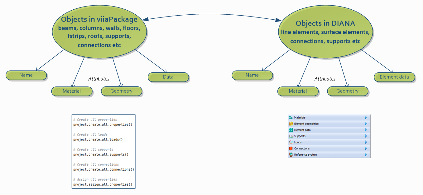
Figure 3.1 - Object structure in viiaPackage compared to DIANA.
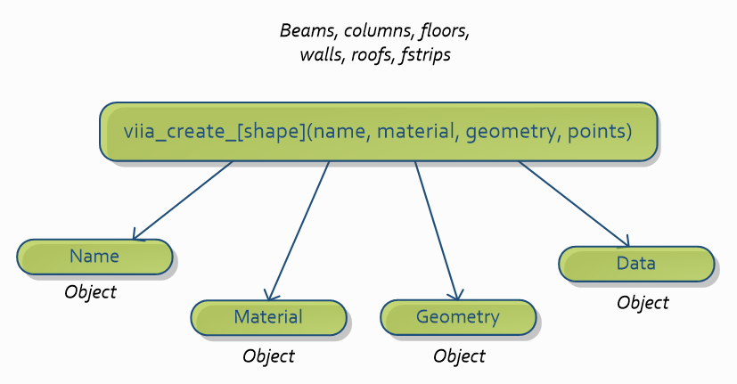
Figure 3.2 - Creating different structural elements.
The collections attribute of ‘Project’ contains lists of the structural objects and sub-objects.
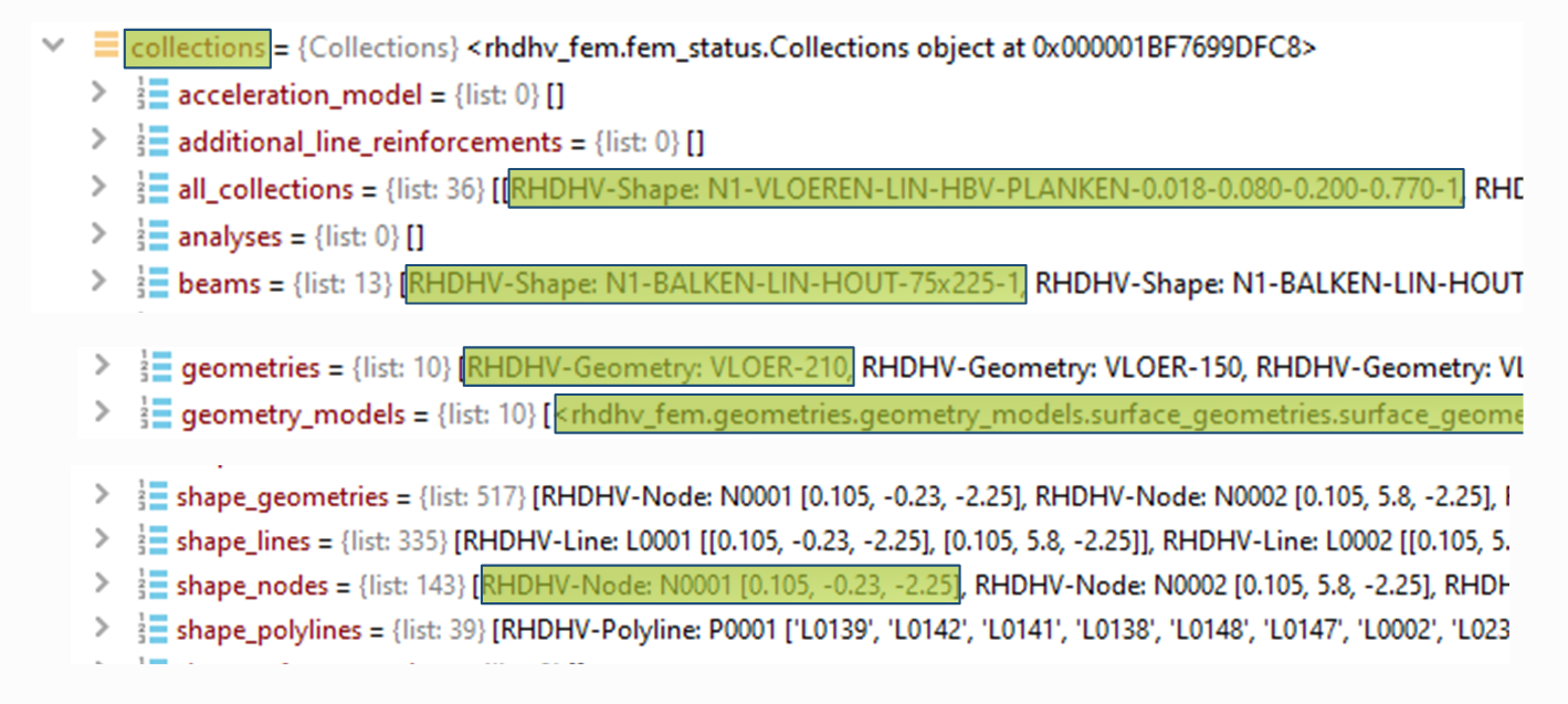
Figure 3.3 - Object information accessible via Collections.

Figure 3.4 - Instructions on comparison between DIANA and viiaPackage.
3.1.2. Alternative methods to create structural elements
Warning
The function shown below to create foundation walls and strips was deprecated in viiaPackage version 65. See step 4 for two examples of how to use the new function.
Some alternative methods to build Wall/Fstrip with viiaPackage:
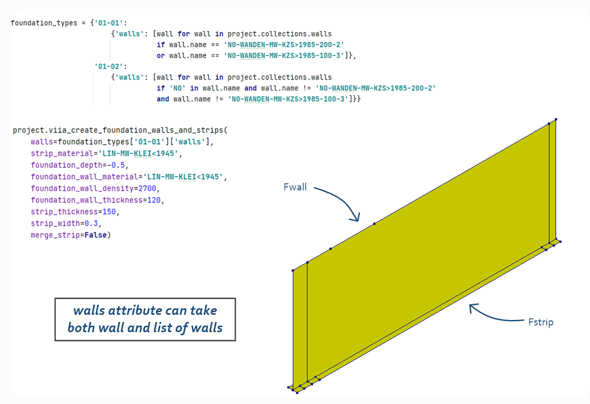
Figure 3.5 - Alternative methods to build foundation wall and strip.
Figure 3.6 - Instructions on simplifying foundation strips.
Some alternative methods to build roofs with viiaPackage:
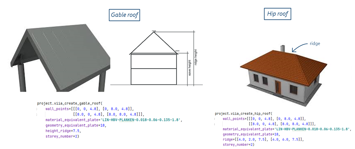
Figure 3.7 - Alternative methods to build roof.
Alternatively, roof plates can be created manually, and then rafters and collar ties can be added using the grid system as explained in step 6.
Additional methods of varying mass/loads in viiaPackage:
Adding mass to a surface object – wall, floor, roof, fstrips:
project.viia_adjust_mass_of_surface(mass, floor)
Adding mass of a line object – beams, columns:
project.viia_create_linemass_beam(beam/column, load)
Figure 3.8 - Instructions on theory for creating roofs and fstrips in alternate ways.

Figure 3.9 - Instructions on theory for creating roofs and fstrips in alternate ways, second part.
3.1.3. Using self-created function to simplify your work
A custom function to adjust foundation strips can be used. An example function is available in help_functions.py.
Usage: Import a function and call it in your model script before saving the json.
from help_functions import adjust_shapes
adjust_shapes(project=project, shapes=project.collections.fstrips, precision=5, simplify=0.01)
The corners will not be as beautiful as done manually, but it will speed up your work!
Warning
The functions shown below to create walls were deprecated in viiaPackage version 65. Instead, walls should now in general be created using the grid system, as explained in step 4. The functions below are still supported, however the shape names are now automatically generated, so instead of the name, the layer should be given instead.
Simplification of foundation modeling using custom functions:
Creating walls can be time consuming as by default you require to specify the whole contour of the wall.
Using simple function to help with wall creation.
Wall_1 = project.viia_create_wall(
    'N0-WANDEN-MW-KLEI>1945-100-1', 'MW-KLEI>1945', 100,
    [[[24.8, 10.5,0],
    [24.8, 6.8, 0],
    [24.8, 6.8, 2.8],
    [24.8, 10.5, 2.8]]])
Wall_2 = project.viia_create_wall(
    'N0-WANDEN-MW-KLEI>1945-100-2', 'MW-KLEI>1945', 100,
    [[[24.8, 6.8, 0],
    [29.8, 6.8, 0],
    [29.8, 6.8, 2.8],
    [24.8, 6.8, 2.8]]])
Can be simplified by creating a simple function to assist you in wall creation:
def create_simple_wall(name: str, material: str, thickness: int, starting_point: List[float],
                       length: List[float], height: float) -> Tuple[Shapes, List[float]]:
    wall: Shapes = project.viia_create_wall(name, material, thickness,
    [[[starting_point[0], starting_point[1], starting_point[2]],
    [starting_point[0]+length[0],
    starting_point[1]+length[2], starting_point[2]],
    [starting_point[0]+length[0], starting_point[1] +
    length[2], starting_point[2]+height],
    [starting_point[0], starting_point[1], starting_point[2]+height]]])
    end_point = [starting_point[0]+length[0],
    starting_point[1]+length[2], starting_point[2]]
return wall, end_point
The function is also available in help_functions.py distributed with the workshop files.
This produces more readable and clear wall descriptions:
wall_1, wall_1_end = create_simple_wall('N0-WANDEN-MW-KLEI>1945-100-1', 'MW-KLEI>1945', 100,
                                        starting_point=[24.8, 10.5, 0],
                                        length=[0, -3.7],
                                        height=2.8)

wall_2, wall_2_end = create_simple_wall('N0-WANDEN-MW-KLEI>1945-100-2', 'MW-KLEI>1945', 100,
                                        starting_point=wall_1_end,
                                        length=[5, 0],
                                        height=2.8)
Figure 3.10 - Instructions on simplified function for creating walls.
3.1.4. Creating custom material in FEM package
CASE: Tension rods (Trekstangen) are present in the building. These tension rods do not take any compressive forces only tensile.
Possible solution:
Model tension rods as truss elements
Apply custom nonlinear material
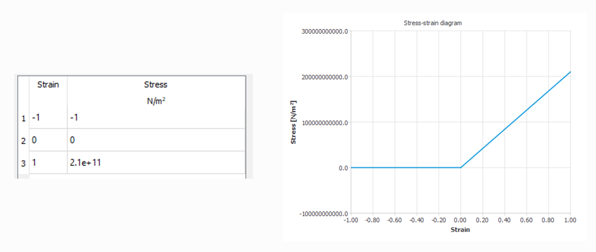
Figure 3.11 - Nonlinear material.
First, create material model in DIANA with dummy values.
Note required material parameters
Note the syntax required for the material creation
addMaterial( "Material 2", "MCSTEL", "UNIAXI", [] )
setParameter( MATERIAL, "Material 2", "ELASTI/ELASTI/YOUNG", 1 )
setParameter( MATERIAL, "Material 2", "ELASTI/MASS/DENSIT", 2 )
setParameter( MATERIAL, "Material 2", "ELASTI/EPSSIG", [ 0, 0, 1, 1, 2, 2 ] )
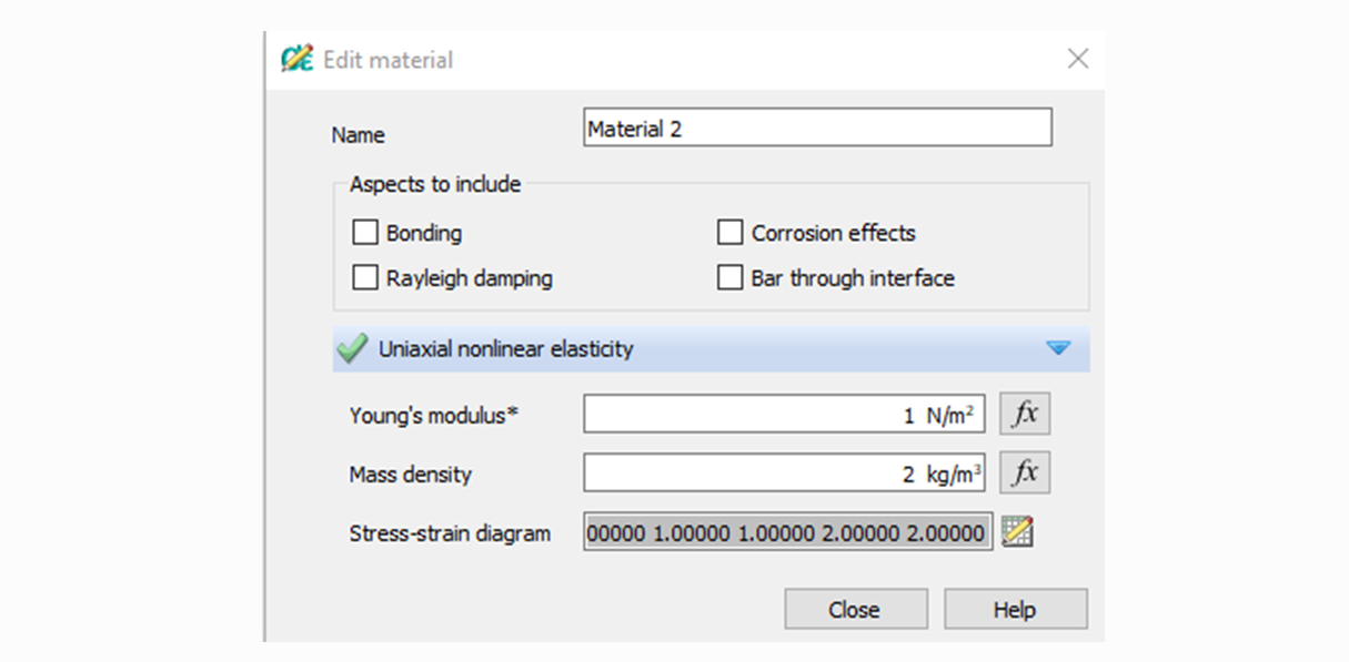
Figure 3.12 - Non-linear material-model in DIANA.
First, lets create the class to contain our custom material.
It should be based on MaterialModel class
It should accept material parameters as arguments, but not density.
Make sure to first import the MaterialModel class from FEM package:
from haskoning_structural.materials import MaterialModel
Then create the custom material model:
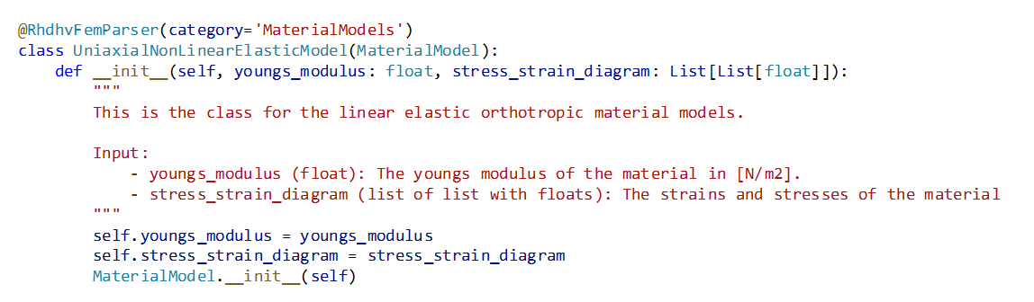
Figure 3.13 - Custom material-model.
Then add a property attribute to set the material to non-linear:
@property
def is_linear(self):
    return False
And define how this material is created in DIANA:
def to_diana(self, density: float):
    parameters = {
        'ELASTI/ELASTI/YOUNG': self.youngs_modulus,
        'ELASTI/EPSSIG': _diana_diagram(self.stress_strain_diagram),
        'ELASTI/MASS/DENSIT': density}
    return {**parameters}
Define material model keywords:
def get_diana_material_model(self):
    """ Getter for the material model which should be used in DIANA."""
    return {'MCSTEL': 'UNIAXI'}
Create a creation function that creates the object and register in the project:
def fem_create_uniaxial_non_linear_elastic_model(project: 'Project', youngs_modulus: float,
                                                 stress_strain_diagram: List[List[float]]):
    return project.add(UniaxialNonLinearElasticModel(youngs_modulus=youngs_modulus,
                                                 stress_strain_diagram=stress_strain_diagram))
Create a beam and convert it to truss:
truss = project.viia_create_beam(name='N0-BALKEN-LIN-STAAL-50x50-1', material='LIN-STAAL', geometry='50x50',
                                 points=[[0, 0, 0], [1, 0, 0]])
project.viia_truss(truss)
Define stress strain diagram:
E_s = 2.1e+11
stress_strain_diagram = [[-1, 0, 1], [-1, 0, E_s]]
And create the material:
mat_model = fem_create_uniaxial_non_linear_elastic_model(project=project,
                                                        youngs_modulus=E_s,
                                                        stress_strain_diagram=stress_strain_diagram)
new_mat = project.create_user_defined_steel(name='LIN-STEEL-NO-COMPRESSION', material_model=mat_model)
Finally assign new material to the truss element:
truss.set_material(new_mat)

Figure 3.14 - Instructions on creating custom materials using viiaPackage.
3.1.5. Getting a point on an inclined plane
Sometimes, there is a need to add a point on inclined plane. These points can cause a lot of problems if computed incorrectly. But how to find it? You can make use of large math library provided by fem client!
CASE:
you have a sloped plane as depicted in the figure;
you want to create a column that goes up to the plane and then stops
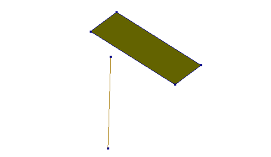
Figure 3.15 - Case: Inclined plane supported by a column.
Possible solution:
coulumn_bottom_point = [3.0, 8.0, 3.0]
coulumn_top_point = fem_point_to_plane(point=coulumn_bottom_point,
                                       plane=roof_01.contour.get_points(),
                                       direction=[0,0,1],
                                       return_intersection= True)
column = project.viia_create_column(
    'N3-KOLOM-LIN-STAAL-K100x200x5-1',
    'LIN-STAAL',
    'K100x200x5',
    [coulumn_bottom_point, coulumn_top_point])
Figure 3.16 - Instructions on finding a point on an inclined plane.
3.1.6. Rotating in viiaPackage
Sometimes coordinate systems needs to be transformed.
Parts of the building that are on an angle.
Various truss systems
Inclined roofs
Etc.
A challenge to calculate all required points
CASE:
You would like to create a beam that’s is inclined 30 degrees
You want the length of the beam to be 5 meters

Figure 3.17 - Case: Create rotated beam.
There are several ways to do this:
Calculate the position of correct point with trigonometry (2D): 𝑥=cos 𝑡∙ℎ𝑦𝑝𝑜𝑡𝑒𝑛𝑢𝑠𝑒 𝑦=sin 𝑡∙ℎ𝑦𝑝𝑜𝑡𝑒𝑛𝑢𝑠𝑒
Calculate rotation matrix (R) for an angular rotation around an specified axis (b) (3D) To get direction unit vector 𝐜=𝑹∙𝒂 Calculate length vector c*L The function to do these rotations are available in help_functions.py
rot(vector,theta)
np.dot(rotation_matrix(axis, theta), vector)
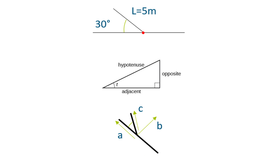
Figure 3.18 - Calculating rotations.
3.1.7. Checks in viiaPackage
The viiaPackage contains check function that helps inspect your model for some issues. The check functions can be called using:
project.viia_check_beam_rotation()
project.viia_check_element_angle()
project.viia_check_tyings()
The functions create text files (only if checks failed) in your working directory with the results of the check.
These checks are handy because:
Checks if any beams can freely rotate
Checks if elements have a correct shape
Checks over-constraints for tyings
3.1.8. Excercise 1 - Custom material
Use the custom material example (as discussed before) and modify it so that Rayleigh damping coefficients can be specified by a user in fem_create_uniaxial_non_linear_elastic_model(). The coefficients are correctly transferred to DIANA once the material is created. Once you try running the function something unexpected will happen! (You should be able to solve it!)
Exercise mainscript
Exercise second script
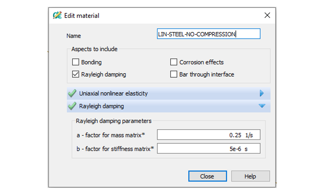
Figure 3.19 - Material in DIANA.
C:Users903031DocumentsVIIAviiapackagedocsworkshops_staticExcersice1Materials.png
Solution
The following recording shows the solution of the excercise:

Figure 3.8 Instructions on solution of excercise 1.
Rayleigh parameters should be accepted into the function:
def fem_create_uniaxial_non_linear_elastic_model(project: 'Project', youngs_modulus: float,
                                                 stress_strain_diagram: List[List[float]],
                                                 rayleigh: List[float]):
ReyleighDamping object should be created with the parameters within the function:
aspects = [RayleighDamping(*rayleigh)]
And then passed into the material Class
return project.add(UniaxialNonLinearElasticModel(youngs_modulus=youngs_modulus,
                                                 stress_strain_diagram=stress_strain_diagram,
                                                 aspects=aspects))
There, it should be assigned to an attribute ‘aspects’
self.aspects = aspects
Within to_diana() method aspects should be converted to dictionary with correct syntax and returned:
def to_diana(self, density: float):
    parameters = {
        'ELASTI/ELASTI/YOUNG': self.youngs_modulus,
        'ELASTI/EPSSIG': _diana_diagram(self.stress_strain_diagram),
        'ELASTI/MASS/DENSIT': density}
    # Get all the aspect information
    aspect_dict = get_diana_aspect(self.aspects)
    return {**parameters, **aspect_dict}
And the unexpected issue?
Fem-client check if expected materials are applied. The check should be extended:
@material_model.setter
def material_model(self, new_material_model: MaterialModel):
    if not (isinstance(new_material_model, (LinearElasticModel, PlasticityModel))
            or "UniaxialNonLinearElasticModel" in new_material_model.__class__.__name__):
        raise NotImplementedError(
            f"ERROR: The material model {new_material_model} is not applicable for {self.name}.")
    self.__material_model = new_material_model
3.1.9. Excercise 2 - Different ways of creating roofs
Remove the existing roof in the model and create a hip roof with an inclination of 60 degrees for both sides (shorter and longer).
Solution
The following recording shows the solution of the excercise:

Figure 3.9 Instructions on solution of excercise 2.
# Removing the roof elements
for roof in reversed(project.collections.roofs):
    roof.remove_shape()
# Creating the roof
height = (5.64-0.105)*math.tan(60*pi/180)
z_ridge = height + 7.29
x_ridge_1 = 0.105+ math.tan(60*pi/180)/height
x_ridge_2 = 8.51- math.tan(60*pi/180)/height
project.viia_create_hip_roof(
    wall_points=[[[ 8.51, 0.105, 7.29 ],[ 0.105, 0.105, 7.29 ]],[[ 0.105, 5.64, 7.29 ],[ 8.51, 5.64, 7.29 ]]],
    material_equivalent_plate='LIN-HBV-PLANKEN-0.018-0.06-0.135-1.8',
    geometry_equivalent_plate=18,
    ridge=[ [ x_ridge_1, (5.64-0.105)/2, z_ridge ], [ x_ridge_2, (5.64-0.105)/2, z_ridge ]],
    storey_number=3)
3.1.10. Excercise 3 - Cavity walls with modification of the loads/mass
Warning
As of viiaPackage version 65, cavity walls should be created as explained in step 6.
Create cavity walls for walls with openings on the ground floor and first floor with the same material, geometry and cavity of 110 mm. Hint: Use fem_copy_polyline Use viia_create_mass_all_wall_openings() to create the line masses for all openings. Add a mass of 150 kg/m to all the line masses. Check if the line masses are placed correctly and make necessary adjustments.
Solution
The following recording shows the solution of the excercise:

Figure 3.10 Instructions on solution of excercise 3.
# Creating the cavity walls
wall_list = ['N2-WANDEN-MW-KLEI<1945-150-92','N3-WANDEN-MW-KLEI<1945-150-16']
cavity = 0.11
for wall_name in wall_list:
   wall = fem_find_object(wall_name, project.collections.walls)
   wall_old_contour = wall.contour
   normal_vector_outward = wall.outward_vector()
   wall_new_contour = fem_copy_polyline(wall.contour, dx=normal_vector_outward[0] * cavity,
                                        dy=normal_vector_outward[1] * cavity)
   wall_new_openings = [fem_copy_polyline(opening, dx=normal_vector_outward[0] * cavity,
                                          dy=normal_vector_outward[1] * cavity) for opening in wall.openings]
   project.create_wall(name = wall.name+'Cavity', material = wall.material, geometry = wall.geometry,
                       contour = wall_new_contour, openings = wall_new_openings)
# Creating the line masses and removing the additional masses
project.viia_create_mass_all_wall_openings()
remove_list = []
for shape in project.collections.line_masses:
    if wall_list[0] + 'Cavity' in shape.name or wall_list[1] + 'Cavity' in shape.name:
        remove_list.append(shape)
for shape in remove_list:
    fem_find_object(shape,project.collections.shapes).remove_shape()
# Creating the lintels and adding the mass of the linemasses to the lintels
project.viia_create_lintel(fem_find_object(
                           'N2-WANDEN-MW-KLEI<1945-150-92',project.collections.walls), 2, 'LIN-BETON', '100x100')
project.viia_create_lintel(fem_find_object(
                           'N2-WANDEN-MW-KLEI<1945-150-92',project.collections.walls), 3, 'LIN-BETON', '100x100')
remove_list_2 = [
    "N2-WANDEN-MW-KLEI<1945-150-92-LIJNMASSA-BOVEN-3", "N2-WANDEN-MW-KLEI<1945-150-92-LIJNMASSA-BOVEN-2"]
for line_mass in remove_list_2:
    line_mass_load = fem_find_object(line_mass, project.collections.line_masses).material.name.split('-')[-1]
    fem_find_object(line_mass, project.collections.line_masses).remove_shape()
for lintel in project.collections.lintels:
    project.viia_create_linemass_beam(lintel,float(line_mass_load) * 9.81)
3.1.11. Excercise 4 - Performing checks on the model
Take the model in the exercise files and identify issues with it as reported by check functions. Should you correct all reported issues? Propose how you would solve them.
Solution
The following recording shows the solution of the excercise:

Figure 3.11 Instructions on solution of excercise 4.
Two issues should have been found:
That beam-z axis direction is wrong;
That element angles are incorrect.
Beam-z axis direction can be ignored as it is parallel to the correct axis and it is for a line mass
Distorted element should be corrected by modifying foundation strips.
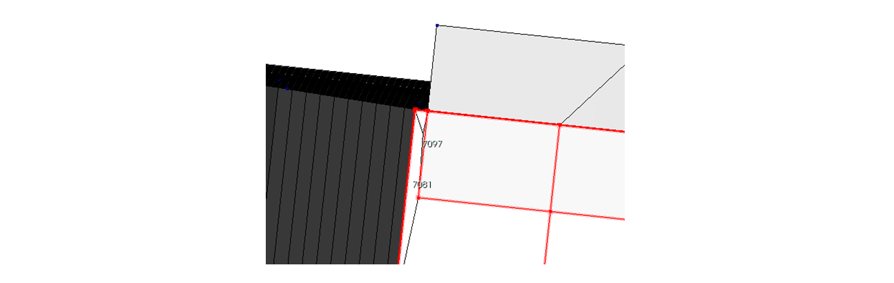
Figure 3.12 Figure 3.24 - Nodenumbers in model in DIANA.
3.1.12. Excercise 5 - Connecting truss to an inclined roof
Add a truss to the roof and make sure that the truss is placed in the center of the roof. All points of the truss are correctly imprinted in the roof. Sections and properties used are not relevant.
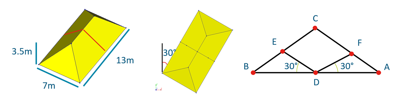
Figure 3.13 Excercise 5.
Solution

Figure 3.14 Figure 3.26 - Instructions on solution of excercise 5.
Define rotated points, rotation matrix and direction vectors:
vector_x = rot([7, 0], -30)
vector_y = rot([0, 13], -30)
rot_matrix = rotation_matrix([vector_y[0]/13, vector_y[1]/13, 0], 30.)
rot_matrix_2 = rotation_matrix([vector_y[0]/13, vector_y[1]/13, 0], -30.)
direction = np.dot(rot_matrix, fem_unit_vector(
    [-vector_x[0], -vector_x[1], 0]))
direction_2 = np.dot(rot_matrix_2, fem_unit_vector(
    [vector_x[0], vector_x[1], 0]))
Define all points:
point_A = [vector_y[0]/2, vector_y[1]/2, 0]
point_B = [vector_y[0]/2+vector_x[0], vector_y[1]/2+vector_x[1], 0]
point_C = [vector_y[0]/2+vector_x[0]/2, vector_y[1]/2+vector_x[1]/2, 3.5]
point_D = [vector_y[0]/2+vector_x[0]/2, vector_y[1]/2+vector_x[1]/2, 0]
point_E = fem_point_to_plane(point_D, roof_E.contour.get_points(), direction)
point_F = fem_point_to_plane(point_D, roof_F.contour.get_points(), direction_2)

Figure 3.27 - Excercise 5 solution in DIANA.
Create all the beams:
project.viia_create_beam(name='N1-BALKEN-LIN-HOUT-75x180-1',
                         material = 'LIN-HOUT',
                         geometry = '75x180',
                         points = [point_A, point_B])
project.viia_create_beam(name='N1-BALKEN-LIN-HOUT-75x180-2',
                         material = 'LIN-HOUT',
                         geometry = '75x180',
                         points = [point_A, point_C])
project.viia_create_beam(name='N1-BALKEN-LIN-HOUT-75x180-3',
                         material = 'LIN-HOUT',
                         geometry = '75x180',
                         points = [point_C, point_B])
project.viia_create_beam(name='N1-BALKEN-LIN-HOUT-75x180-4',
                         material = 'LIN-HOUT',
                         geometry = '75x180',
                         points = [point_D, point_E])
project.viia_create_beam(name='N1-BALKEN-LIN-HOUT-75x180-5',
                         material = 'LIN-HOUT',
                         geometry = '75x180',
                         points = [point_D, point_F])
3.1.13. Final tips
Result handling:
Check the location of the result filled prior to running the functions
Check result items in the specific folders after running the function
Modelling:
Line masses are created for both inner and outer leaves of cavity walls. This should be checked, and additional line masses should be removed
Simplify geometry eg. Roof – 45 degrees, floors which are slightly different levels can be made at the same level, Wall inclined less than 10 degrees can be straightened.
General:
If DIANA commands are added to the main/model scripts, these will not function in ABAQUS. Check this before proceeding with the model.
The Workarounds shown should be secondary. It is important that you report the bugs as soon as you find them.
Build custom functions to speed up your process. And share!
Always check models. Don’t completely rely on the package.
Some functions need to be added before viia_create_model(), be aware of that.
Strengthening:
Run the script in PyCharm prior to running it in DIANA to prevent any errors .
If the script runs through, check the comments in the log file to see if the measure has been applied correctly.
Check again in DIANA thoroughly (Location, Geometry (including eccentricity), Material).
Note
We hope you enjoyed this workshop. Let us know if you have any question or suggestion.