6. Phase 4: Validation
After the technical kick-off, the engineer needs to validate the expectancies that were discussed with the LE for each critical element. If the critical element complies, then it can be concluded that the remaining elements of the building comply as they have better capacity than the critical element with respect to the failure mechanism under consideration. However, if the critical element does not comply, then we cannot conclude that the remaining building elements comply. Thus, two steps need to be followed. Firstly, we need to recommend strengthening measure to the failing critical element, secondly, we need to verify if the subsequent critical/governing element complies. This sequence should be followed until the selected critical element is found to comply without requiring a strengthening measure.
Whether the critical elements comply with the criteria stated in the Basis of Design NLTH [RA4] is checked using different validation methods stated below:
Validation with reference to NLTH buildings
Validation with engineering judgement
Validation with simplified calculation tools
These validations are applied depending on the requirements of the building at hand. The method of assessment under contract with NCG (NLTH or NLPO) determines which validation method can be applied. Thus, the sections below are classified into REF-NLTH and NLPO depending on the type of assessment agreed upon with NCG. Each validation method is further elaborated within these sections.
6.1. REF-NLTH
This section is for the validation of REF-NLTH buildings. These buildings are primarily validated using NLTH results of similar buildings that were previously analyzed. However, if it is not possible to validate using NLTH results due to lack of comparable buildings or other reasons then validation through engineering judgment or simplified calculation tools are used.
6.1.1. Validation with reference to NLTH buildings
6.1.1.1. Finding Reference Objects
This validation method is conducted using NLTH results of comparable buildings as reference to verify the behaviour of the critical elements. Comparable/reference buildings can differ per critical element and failure mechanism. The important parameters stated in section 3 are used to select the reference NLTH building. A critical element is then compared with a similar element in the reference NLTH building.
To assist the engineer with the process of finding reference buildings, preselection of possible NLTH buildings is done using myviia engineering database. This preselection list of buildings is outputted in terms of a ranking system based on the parameters of section 3 with the ‘most comparable’ building ranked first. The engineer should use this preselection list only as a guide to find a reference building. It is the responsibility of the engineer to carefully select the most comparable reference building and verify the behaviour of the critical element. Refer to section 3.1 for more information about the Preselection Tool.
6.1.1.2. Finding building elements in Reference objects
To find comparable building elements inside of the selected reference NLTH buildings, the engineer can use the Reference Approach Tool. In this tool, models of the selected reference NLTH buildings are loaded in and shown in an interactive 3D plot. When the dimensions and materialisation of the critical element are filled in, the tool suggests and highlights the most comparable building elements inside of the plot.
The Reference Approach Tool can be run locally using the following code:
from viiapackage.tools.reference_approach_tool.viia_reference_approach_tool import viia_reference_approach_tool
viia_reference_approach_tool()
Refer to section 12 for extra setup steps, in case the Reference Approach Tool does not start up when running the code.
The Reference Approach Tool consists of 4 main steps:
Selecting your object
Adding relevant information about the critical element
Selecting elements in scoring table
Visualizing 3D-model with selected element
Firstly, the Structural engineer selects their object code on the homepage. The dashboard looks through the selected reference objects (specified in myviia) for 3D-models. If those 3D-models are present, these models are loaded into the dashboard.
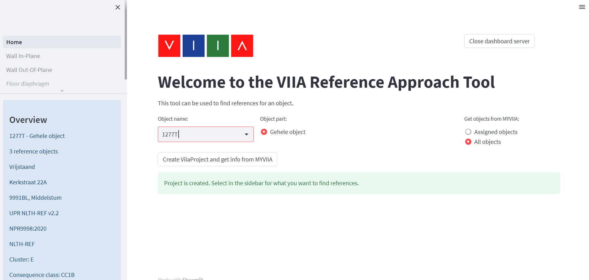
Figure 6.12 Selecting your object and loading in the reference object models.
Secondly, the Structural engineer can fill in the relevant properties of their critical element for the failure mode they are investigating.
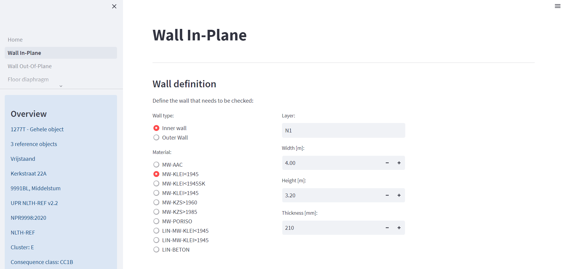
Figure 6.13 Adding relevant information about the critical element.
The Structural engineer subsequently receives an ordered table of all the building elements in the reference models. This ordering is based on the similarity between the critical element and the building elements in the models. A weighted scoring system is used, which is elaborated upon in section 13. The table can also be exported to an excel file.
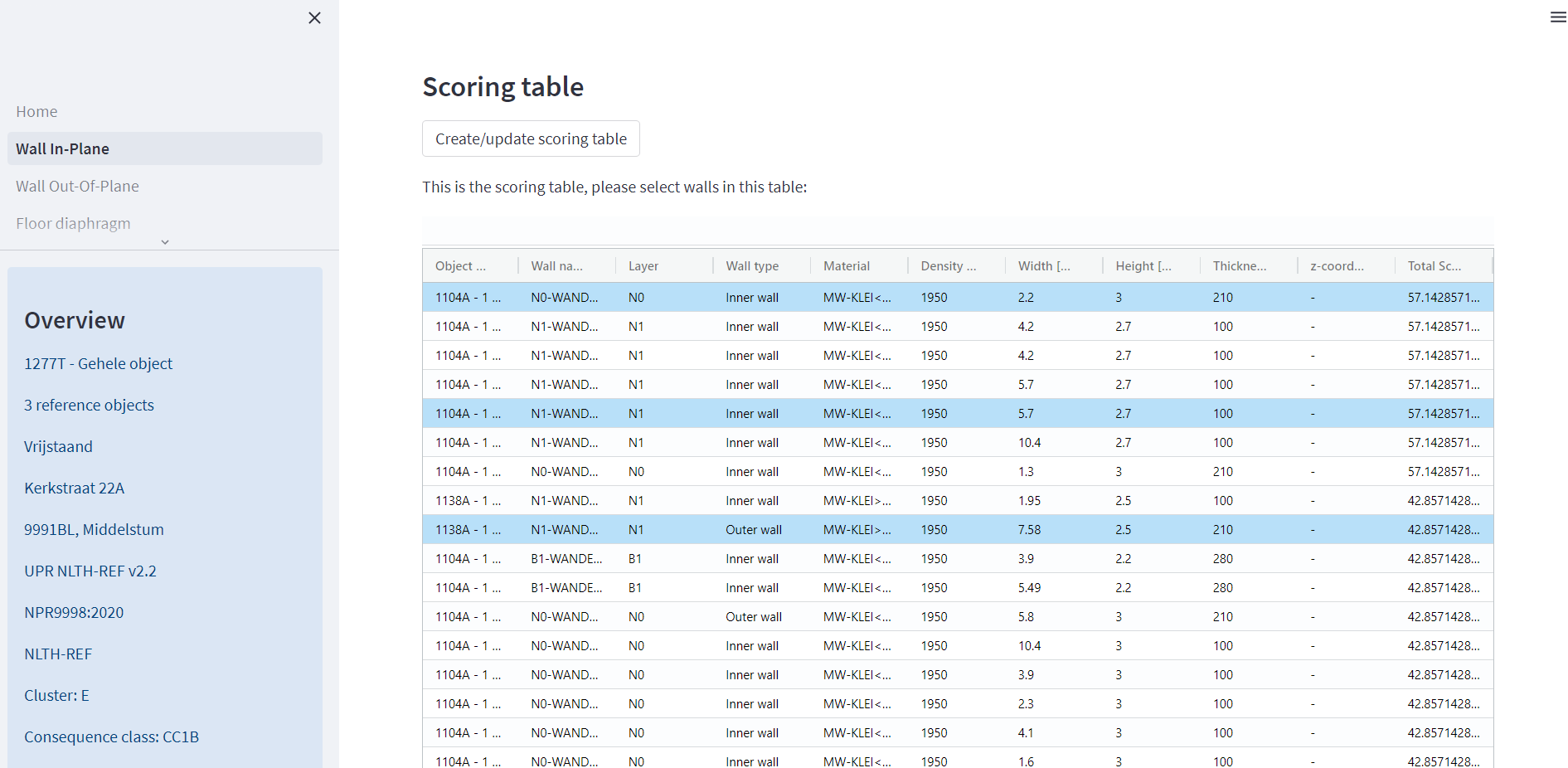
Figure 6.14 Selecting elements in scoring table (with downloadable Excel).
After the building elements are selected in the table, the 3D-model of the reference object is shown below the table. Overview pictures of the object and links to relevant BOX folders are also shown. The selected elements are highlighted in the 3D-model. The shown model can be also be saved as a picture to be used in reporting.
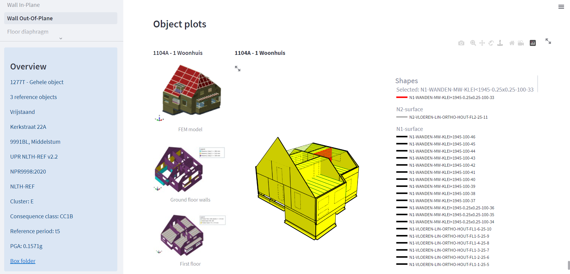
Figure 6.15 Visualising 3D-models with selected elements.
The workflow through the Reference Approach Tool has currently been implemented for the In-Plane and Out-Of-Plane failure modes.
Following the selection of the reference building (and building element) for the specific failure mode, the engineer determines by looking at the available information whether the critical element fails. If the conclusion differs from the comparison with the reference building, it must be elaborated why a different conclusion is drawn in the TVA report.
6.1.2. Validation using VIIA_QE_R376_N073
For buildings that fall into the ‘Krimpje’ category, memo VIIA_QE_R376_N073 can directly be used. This memo contains the NLTH results of five ‘Krimpje’ buildings that were analyzed as part of the Koploper project. Conclusions for buildings or building parts that are similar to ‘Krimpje’ buildings with respect to each failure mechanism are drawn using the five NLTH buildings.
Thus, where applicable, VIIA_QE_R376_N073 can be directly referred and conclusions made without further elaboration in the TVA report. Annex A is now separately available and can be attached at the end of a TVA report.
6.1.3. Validation using simple calculations
If no comparable reference building can be found, the critical element can be validated using simple calculations. For example, the out-of-plane behaviour of a wall can be checked using NLKA as described in Annex H of NPR 2020 [RA3], or the in-plane behaviour of a wall can be checked using the SLaMA method (for the SLaMA calculation a python script is available). The calculations are not elaborated in detail in the TVA report but are supported using images and graphs as much as possible. Only the most important parameters used in the calculation are reported.
6.1.4. Validation with engineering judgment
If no comparable reference building can be found, the element is assessed using engineering judgement. This should be done in consultation with the lead engineer and should be supported with valid arguments in the TVA report.
6.2. NLPO
This section is for the validation of NLPO buildings. These buildings are primarily validated using simplified calculation tools. NLTH reference buildings are not used for the validation of their critical elements. The only difference with a REF-NLTH object is in the validation methods that are primarily applied. Validation with simplified calculation tools, see section 6.1.3, and validation with engineering judgement, see section 6.1.4, are applied for an NLPO building. Specific workflows for NLPO in the validation process of floor behaviour, roof behaviour, out-of-plane and in-plane behaviour of walls are discussed below.
6.2.1. Floor diaphragm validation
For buildings assessed with NLPO, assessment of the floor diaphragm capacity should be carried out according to the flowchart shown in Figure 6.1. The tool to perform the floor diaphragm capacity check can be found on BOX. The result from this tool needs to be documented in Appendix C5, please see the latest template for the correct Appendix.
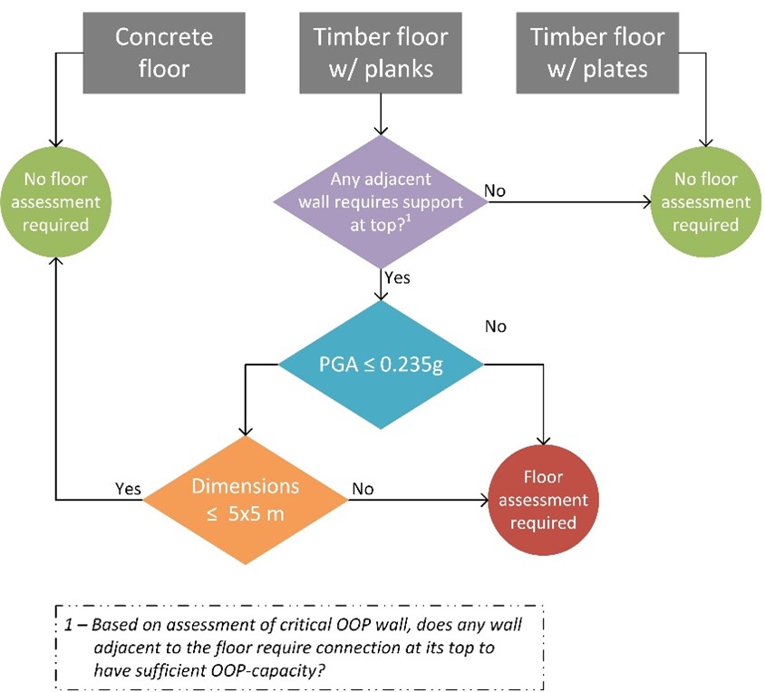
Figure 6.16 Flowchart of floor diaphragm validation
6.2.2. Roof diaphragm validation
For buildings assessed with NLPO, validation of the roof diaphragm capacity should be carried out according to the flowchart shown in Figure 6.2. The tool to perform the roof diaphragm capacity check can be found on BOX. The result from this tool needs to be documented in Appendix C5, please see the latest template for the correct Appendix.
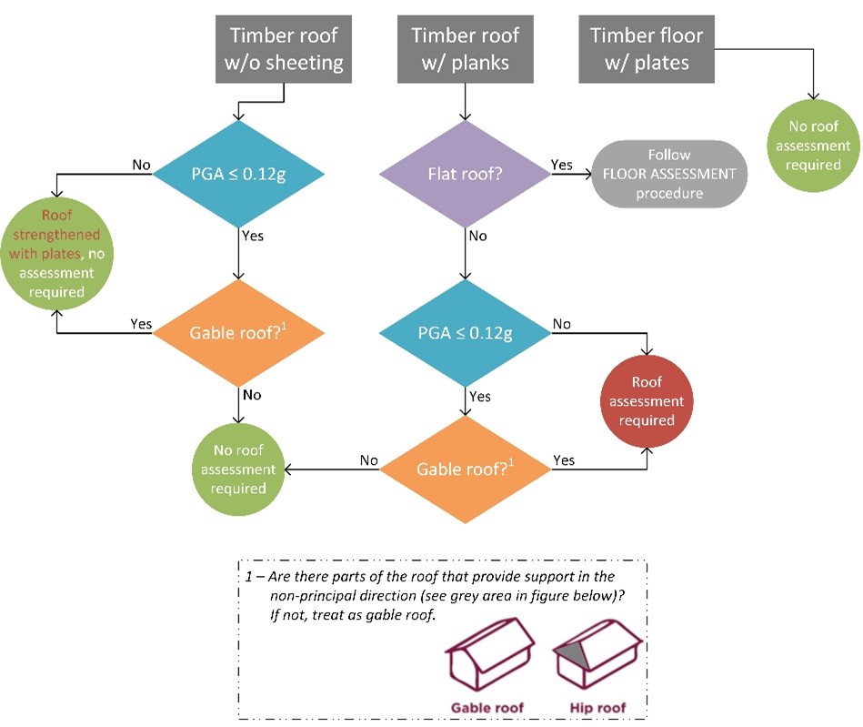
Figure 6.17 Flowchart of roof diaphragm validation
6.2.3. In-plane validation
For buildings assessed with NLPO, in-plane behaviour of the critical wall element(s) is assessed by SLaMA calculation. The use of the SLaMA calculation depends on the type of diaphragm, see the flowchart in In-plane general workflow.. SLaMa calculations are carried out using the envelope method. For the envelope method, no detailed information regarding the critical element is needed, as the method uses the upper and lower bounds. This means that the assessment is carried out using a set of east favorable conditions as a conservative approach. If the element passes using this envelope method, it can be said that the element will always pass, even when the assumptions are incorrect.
6.2.4. Out of Plane validation
For out-of-plane validation of walls in NLPO buildings, NLKA as explained in Annex H of NPR9998:2020 [RA3] is applicable to assess the selected critical wall. The engineer can choose either the ‘L4-tool’ or the NLKA tool from the viiapackage to perform this assessment.
6.2.4.1. NLKA – bottom boundary condition
When performing an NLKA, it is usually safe to assume that the bottom boundary condition is rigid (boundary condition 4). For a masonry strip foundation, the strip width should be at least two times the wall thickness. This is usually the case. Unless it is explicitly mentioned that the foundation strip width is limited (less than two times the wall thickness) or damage has been found in the wall, assuming a rigid boundary condition at the bottom of the wall is justified. If another assumption for the bottom boundary condition is desired, it should first be discussed with the lead engineer.
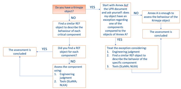
Figure 6.18 Flowchart of NLKA – bottom boundary condition
Retrofitting is described in the next page: ‘Phase 5’.