2. Phase 1 - Starting phase
This is the starting phase where the analysis model is set-up according to a building inspection and the review of the building documents. The analysis model is set-up in python modelscript. At the end of phase 1, a basic preliminary model containing the geometry, cross-sections and materials is created. In the next phase, the analysis model will be extended and prepared for the different analyses.
For the modelling process, the engineer should investigate which information is necessary in order to achieve an adequate model. Also in this phase, reporting is started. Appendices are created for: PSSE- and NSCE-classification and the building overview (containing overviews of floors and roof, walls and foundation).
The steps involved in phase 1 are described in the figure below.
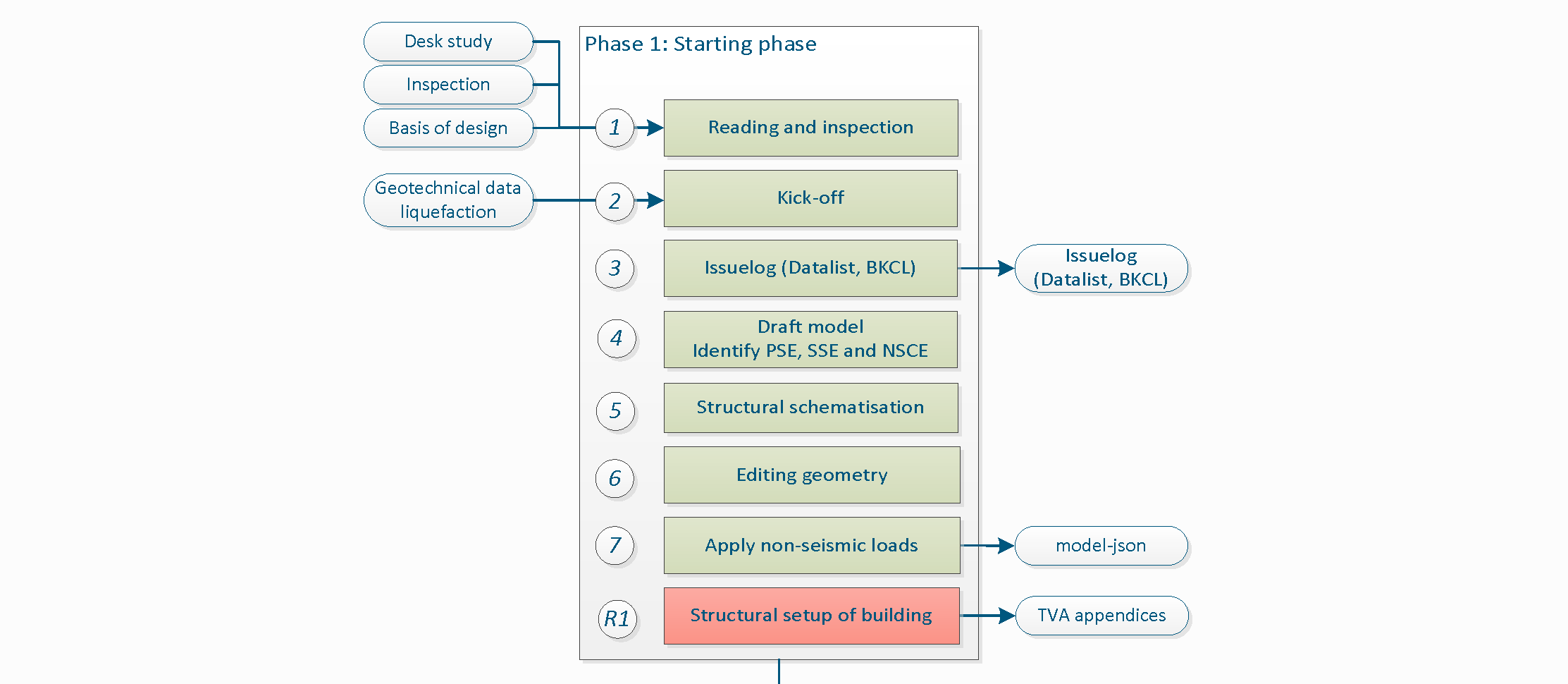
Figure 2.1 Phase 1 - Starting Phase.
Note
For each phase various steps need to be performed. The number assigned at the left side of the step description is used to identify the step and to link it with the corresponding item in the python-script. It is not necessary to perform the steps in the presented order. However all steps in a certain phase should be completely finished before moving forward to the next phase.
2.1. Object start
An object is assigned to you by the VIIA planning responsible (Vincent Huigen). It may be that you are assigned a second object, so that if you have to wait for your first object (analysis), you can spend your time in an efficient way. The project leader will inform the structural engineer if priority of the object is changed. The VIIA planning responsible will send an email with the assigned object number, the project leader, the lead engineer and will be followed up geotechnical advisor (if geotechnical assessment is required). This information will also be added to the MYVIIA webtool. The object can also be an object-part (when the complete object consists of multiple buildings or when a building is split in separate analysis methods).
When you start a new object make sure to create a clean new working directory. The procedure to do this is explained here: How to install the viiaPackage.
In MYVIIA you can find the planning and deadlines of the deliverables. You can also find the number you need to register your hours worked on the object in your timesheets.
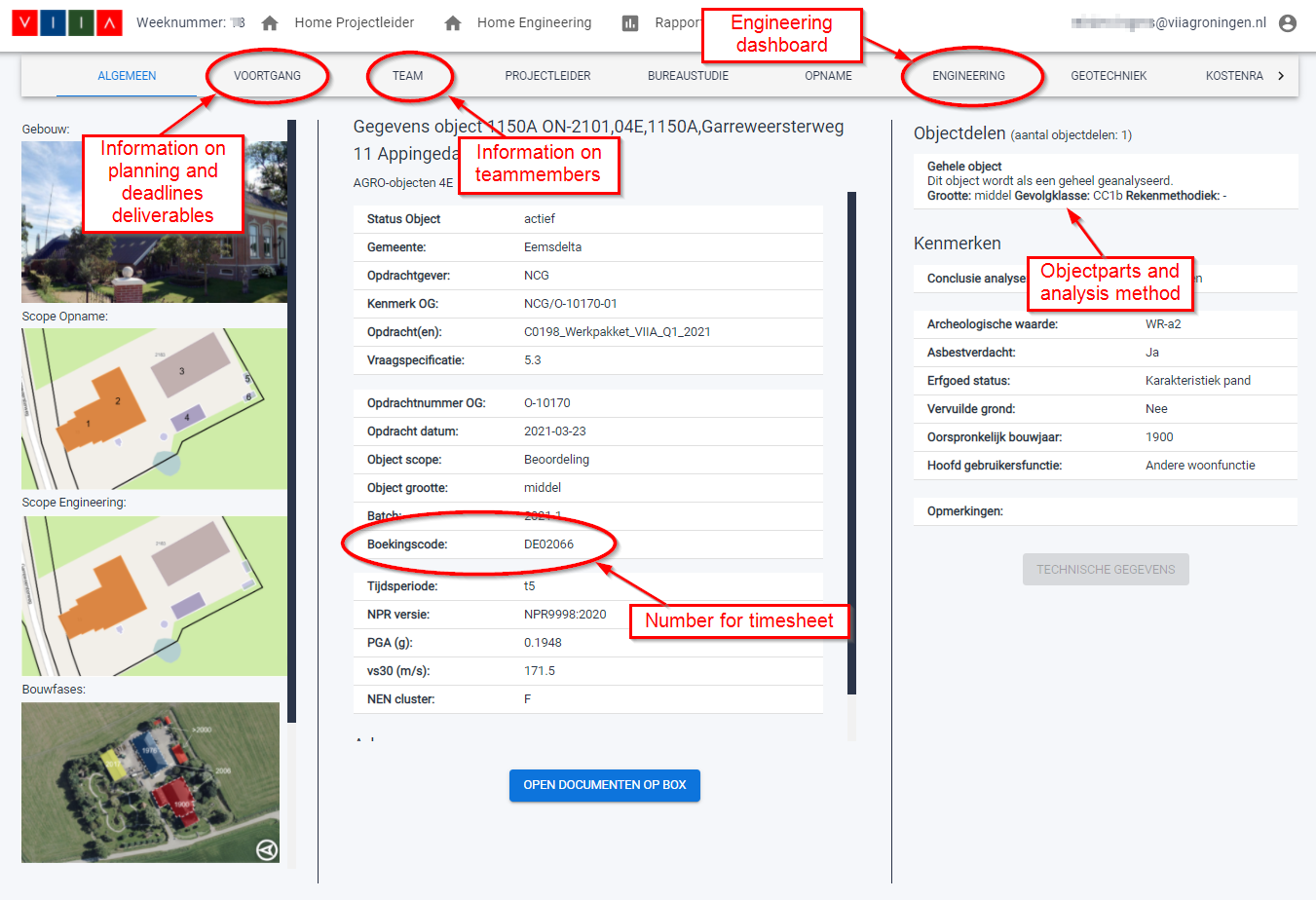
Figure 2.2 Information on MYVIIA webtool relevant for object start.
For RHDHV staff: Use workorder BH4424-103-100 (VIIA uren) for the hours spent on VIIA. These number of hours per week need to comply to the hours registered in the VIIA timesheet registration.
The hours spent on the object should be registered in the Urenportaal. You can request access to the timesheet registration here: email. Be aware that the hours are also used by management and project leaders to monitor the progress and should reflect the hours you work on the object.
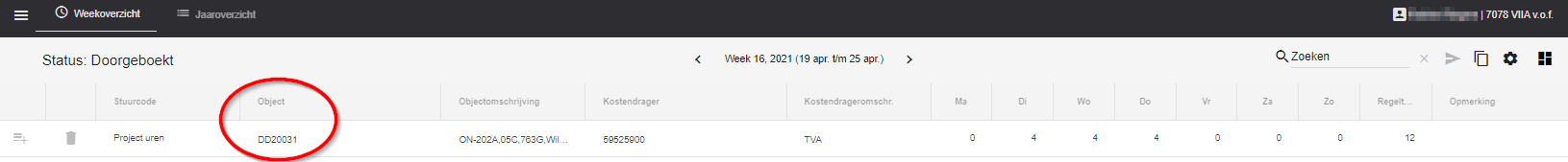
Figure 2.3 VIIA timesheet registration.
2.2. Step 1: Reading and inspection
The first step in the process is to get familiar with the available information on the object. The main source of information for the engineer is the inspection report. This report describes the building, contains the relevant drawings and has checked the situation on site. The site visit has been documented with pictures. This information should be enough to assess the structure.
When the information is incomplete this should be discussed in the Kick-Off meeting. Make sure that you have collected all required information before that meeting. The assumptions for missing information are added in the issuelog in step 3 of the workflow.
There are more sources of information available, but these should only be checked if the inspection report is incomplete or highly doubtful. These additional sources are explained in section How to collect additional information.
2.2.1. Basis of Design
The Basis of Design document contains the general modelling, analysing and assessment approach in VIIA. This document is discussed with the client. When starting an object, the prevailing Basis of Design should be set in MYVIIA and used throughout the process (unless specific reasons, in consultation of the lead engineer, a newer version might be adopted). The goal of the Basis of Design is to reduce the amount of reporting required for the object, all general descriptions are already there. Only deviations go in to the object specific report.
Basis of Design NLTH, v13.0: BoD-NLTH 13.0
2.2.2. Existing Damages
In the inspection report (NL: Opnamerapport), information on existing damages in the building (if any) is documented by the inspection team. If no/not all information regarding existing damages is present in the inspection report and if the structural engineer identifies additional damage from inspection images that (may) impact the seismic capacity of the structure then this must be reported in Section 3.2 of Appendix C1 - ‘Overview Seismic Assessment’. The engineer should include overview drawings of the location of these damages and the (pre-)measures required in Appendix A2 ‘Drawings Retrofitting Measures’.
When reporting the damages, check the following instructions. Damages only require strengthening if this is required to provide for capacity to withstand the seismic actions. Refer to the protocol on damages of NCG.
For ALL damages (Inspection report + noticed by Structural Engineer): Pictures of the damages, with a highlight over it in order to clearly indicate where the damage is, along with a short description in Section 3.2 (called ‘Existing Damage’).
For damages which indicate possible insufficient capacity of the foundation: These damages can have an influence on the assessment of the foundation. Discuss these damages explicitly in the Kickoff. Refer to <Link> for the workflow for assessing foundations.
For damages which require strengthening: Appropriate overview drawings of the strengthening measures in Appendix A2 (‘Drawings Retrofitting Measures’), indicating the locations and dimensions of the measures.
If there are damages that affect the seismic capacity of the structure, the structure falls under a special framework within the NCG. The ‘Kader Verzwakte Constructies’ is a framework that outlines guidelines for dealing with weakened building structures during strengthening operations. This framework is applicable to all buildings falling under the jurisdiction of the NCG. Discuss this with your Lead Engineer and Project Leader during the Kickoff, as they need to notify the NCG as well.
2.3. Step 2: Kick-off
The kick-off if the official start of the engineering phase of the object. The kick-off is a meeting with all team members involved in the object. The presentation for this kick-off needs to be prepared by the structural engineer:
The structural engineer sends email to the project leader asking for a kick-off.
Read through the available documents and drawings on box, see step 1 of the protocol. A presentation needs to be prepared to inform the team and start discussions on the object specifics.
Determine if the geotechnical assessment is required.
The kick-off meeting consist of a general part and a technical part. In the technical part of the kick-off the engineering choices are discussed more in detail with the lead engineer and optional the technical master.
If required a separate meeting needs to be planned in case of a split object. The teamleader will arrange such a meeting to define the cut between the object-parts, see How to handle split-objects.
2.3.1. Geotechnical assessment
In the kick-off meeting the decision is made if geotechnical assessment is required. For this the workflow can be found here: How to assess foundations. The lead engineer is responsible to set this input on MYVIIA.
2.3.2. Classification NSCE / PSSE
In the preparation for the kick-off the engineer should create a list of non-seismic structural elements (NSCE) in the object. The NSCE’s are the elements that are not always required to be modelled in the fem-model and are to be checked with a separate tool (see phase 4 of the workflow).
2.3.3. General
The general part of the meeting the following people are present:
Project leader
Lead engineer
Structural engineer(s)
Geotechnical advisor (optional)
Cost expert (optional)
Head inspector (optional)
Detail engineer (optional)
During the kick-off, the following items are discussed:
General overview of the building (source: Inspection report and MYVIIA), including engineering scope
The roles of the team members
Consideration of knowledge from prior phases
Identify problematic aspects of the building
Discussing ambiguities
Purpose of NLTH and usefulness of it
Reconsidering the proposed calculation method if necessary
Deadline of the object and planning (scheduling data form)
Identification of the seismic elements
Additional the following structural aspects should be considered if present / required:
What to model and what not to include in the model.
Modelling of the foundation.
Material properties and geometry.
Connections between structural elements.
Connections with other adjacent structures.
Possible simplifications.
The PGA on MYVIIA should have been checked (based on GPS coordinates of the address).
Some members will be working on multiple aspects of objects, so it is useful to give a short introduction to the object. The structural engineer gives this introduction by means of a presentation. During the meeting, the team looks ahead in the process to identify possible problems and obstacles so that they can then be addressed as soon as possible. Further, the team establishes a definitive engineering scope. The structural engineer identifies the missing information and presents it during the meeting. The team establishes if it can be reasonably approximated or if further information from the inspecting team/company is required. Only then it is decided for all disciplines to start engineering. A template/example of a kick-off presentation can be found here:
► Template presentation kick-off
During this meeting, discussion may be also raised related to the advantages or suitability of another analysis method for the object, making it clear what can be gained with respect to the method as proposed to the client. In addition, it is wise to discuss during this meeting how the object can be analysed as smart/simple as possible.
In case of an object that will be analysed with two or more analyses methods, the expected splitting line will be shared by the lead engineer in order to prepare the team members of the scope and for the structural engineer to already start working on their object assuming this split. After the technical kick-off a meeting is arranged by the project leader with all lead engineers of the object-parts (assessed with other analysis methods).
Also discussed in this meeting is if a geotechnical assessment should be performed. In general, buildings with shallow foundations with less then 4 levels the geotechnical assessment is not required.
The dates relevant for planning are discussed and the projectleader informs the planner with the agreed planning. There is a form available on box to fill in the scheduling data. These dates will be added on MYVIIA.
2.3.4. Technical
During the technical part of the kick-off the following people that are involved in the object are present:
Lead engineer
Technical master
Structural engineer(s)
Now the engineering issues are discussed more in detail. The discussion can involve but is not limited to the following structural aspects:
What to include and what not to include in the model.
Modelling of the foundation.
Modelling of elements in each layer of the structure
Material properties and geometry.
Connections between structural elements.
Connections with other adjacent structures.
Possible simplifications.
Discuss the OOP graphs for the object.
Discuss the outcome of the preselection tool for similar completed objects.
The information about the structural aspects of the building which is missing or unclear can be assumed with help of the standardisation document (see How to standardise the unknown information from inspection) after consultation with the Lead Engineer in the technical kick-off. Ultimately, the number of unknowns should be eliminated or minimised after the technical kick-off for the structural engineer to be able to start with modelling of the object.
We also look at the strengthening measures that are probably needed and strengthening measures that are usually needed. Depending on the PGA and the experience with similar objects, a strengthening expectation can be shared by the lead engineer. The estimation is mainly made on the basis of experience, and possibly a hand calculation that has been made in advance. The template/example of a technical kick-off presentation is part of the kick-off template above.
2.4. Step 3: Issuelog
This step in the process involves the assumptions made to assess the object. When performing a structural analysis the reality has been schematised in a model with which the behaviour in earthquake situations can be predicted. In the issuelog we collect all (and only those) assumptions that are made to create this model.
The structural engineer will make decisions while modelling, for example dimensions of elements or openings, or choices which material model to use. This is called schematisation of the structure. When dimensions are available from drawings or inspection these can be used. If the element is only visible on pictures (an opening for example), the dimensions are based on the picture. Also the choice of material is part of the schematisation. Schematisation of the model is described in the Basis of Design, and should not be added to the issuelog.
We only need to add assumptions to the issuelog. An assumption is made when we do not have any information in the inspection report, drawings or pictures. For example if the material is not visible we should assume the material. In case the pile-plan is missing, we may assume pile dimensions and positions.
The issuelog is an important document that needs to be sent together with the TVA report to the client at the end of the process. It should be filled with care, giving a clear explanation of what was not clear and which information was missing. The issuelog is also read by the owner and should therefore be a clean overview.
The issuelog Excel-file should be located in the main folder of your object and updated during the complete process.
Todo
Rerun read the issuelog when doing rerun.
2.5. Step 4: Draft model
The default way to set up a model is with Python. To do this, the functionality of the viiaPackage is available. For information on how to install the viiaPackage, refer to How to install the viiaPackage. If you did not do this already, prepare a new clean workfolder before you continue.
The VIIA workflow consists of first creating the analysis model in the modelscript and then analysing the object in the mainscript and in some cases handle the results in the resultscript. The final report is created in the reportscript. In this phase only the modelscript is used. In the end the modelscript will generate a json-file with the analysis model that can be used in following steps.
To aid the engineer, a template is created that can be used as a starting point for the modelling process. This template can be downloaded below, but should already be present if workfolder is properly setup.
Next to this template, an example modelscript is available for reference. Examples that are presented in this documentation are taken from this modelscript. The example can be downloaded from:
Lastly, A cheat sheet is available with the most used functions, as quick reference material:
2.5.1. The modelscript
This section describes the setup and the contents of the modelscript.
2.5.1.1. Structure of the modelscript
The modelscript should be categorised per layer. A layer is defined as a group of structural elements, together forming a building layer. These layers are the basis of the phasing in the analyses and the further processing of the results in the engineering report (ER), also the ‘Technisch Versterkings Advies’ (TVA) for the NCG. The figure below indicates one building layer in the side view of a structure. It is important to note that a layer consists of a floor, and all other elements extending from this floor in upward direction.
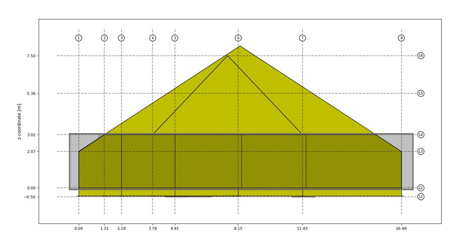
Figure 2.4 Side view of structure.
In case of this building, the layer that is highlighted consists of the ground floor, the walls from the ground floor to the first floor, the columns supporting the first floor and the beams supporting the first floor. Each building layer should be modelled in a separate chapter of the modelscript. Each chapter is subdivided into the steps defined in this protocol. The layout of each chapter therefore takes the form:
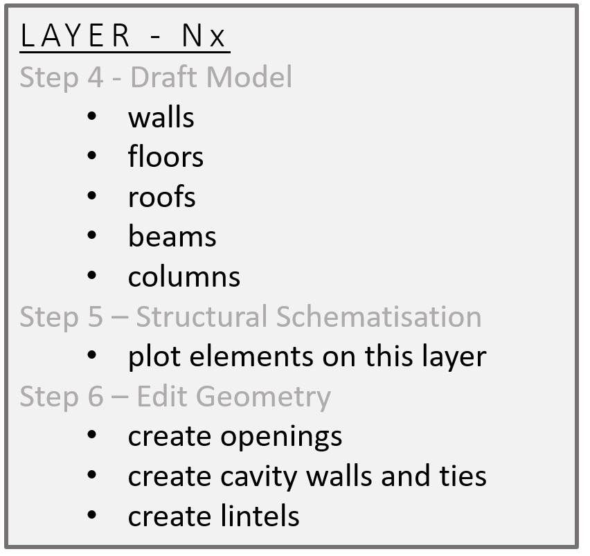
Figure 2.5 Layer layout overview.
Layers should be named and ordered complying to the VIIA naming convention.
Nx
N2
N1 -> Layers above (numbered upwards)
N0 -> Ground floor
B1 -> Basements (numbered downwards)
B2
Bx
F -> All foundation walls, strips and piles
2.5.1.2. Initiating the modelscript
The modelscript is started with the following code:
from viiapackage import *
This loads all functionality required for VIIA. It is not necessary to import the haskoning_structural package.
Start the project with viia_create_project() and use the VIIA object number that is
also in MYVIIA. The version must be 1 for the existing building assessment. When strengthening measures are applied
later the version is going up.
project = viia_create_project(project_name='1017A', version_nr=1)
This function will collect all the required settings for the analysis from the MYVIIA webtool. In case of object-parts (separate analyses of building parts as agreed with the client) you need to provide the object-part that is involved in the analysis. You can find the object part names on the MYVIIA webtool. This is also the case for rerun objects.
project = viia_create_project(project_name='1017A', object_part='Woonhuis', version_nr=1)
2.5.1.3. Setting up a Grid
Starting point of the modelling proces is setting up a relevant grid system. When appropriate dimensions are collected
from the inspection data, an orthogonal grid can be initiated with x- and y-values. The function
viia_create_orthogonal_grid() can be used to create the grid.
x_grid = [0, 4.4, 6.7, 9.4, 12.1, 15.8, 17.9, 35.1]
y_grid = [0, 1.3, 2.1, 3.7, 4.9, 8.1, 11.4, 16.4]
grid = project.viia_create_orthogonal_grid([[x_grid, y_grid]], name='Main Grid')
It is possible to provide different kinds of input for the grid system. For instance, tags can be used to distinguish between gridlines within the grid. For more elaborate explanation of the options of the grid system, please refer to the documentation of the fem-package.
The first grid defined should be the main grid. This grid is used in plotting functions by default. It should be a clear and logical grid (spacing between gridlines should not be less than 2m). Sub-grids are useful for easy modelling building parts.
To add levels to a grid, you can use the function: viia_create_levels()
project.viia_create_levels([-0.5, 0, 2.069, 3.02, 5.36, 7.5])
The grid can be plotted with the following command.
project.viia_plot_grid(show=True)
This will show the following two images:
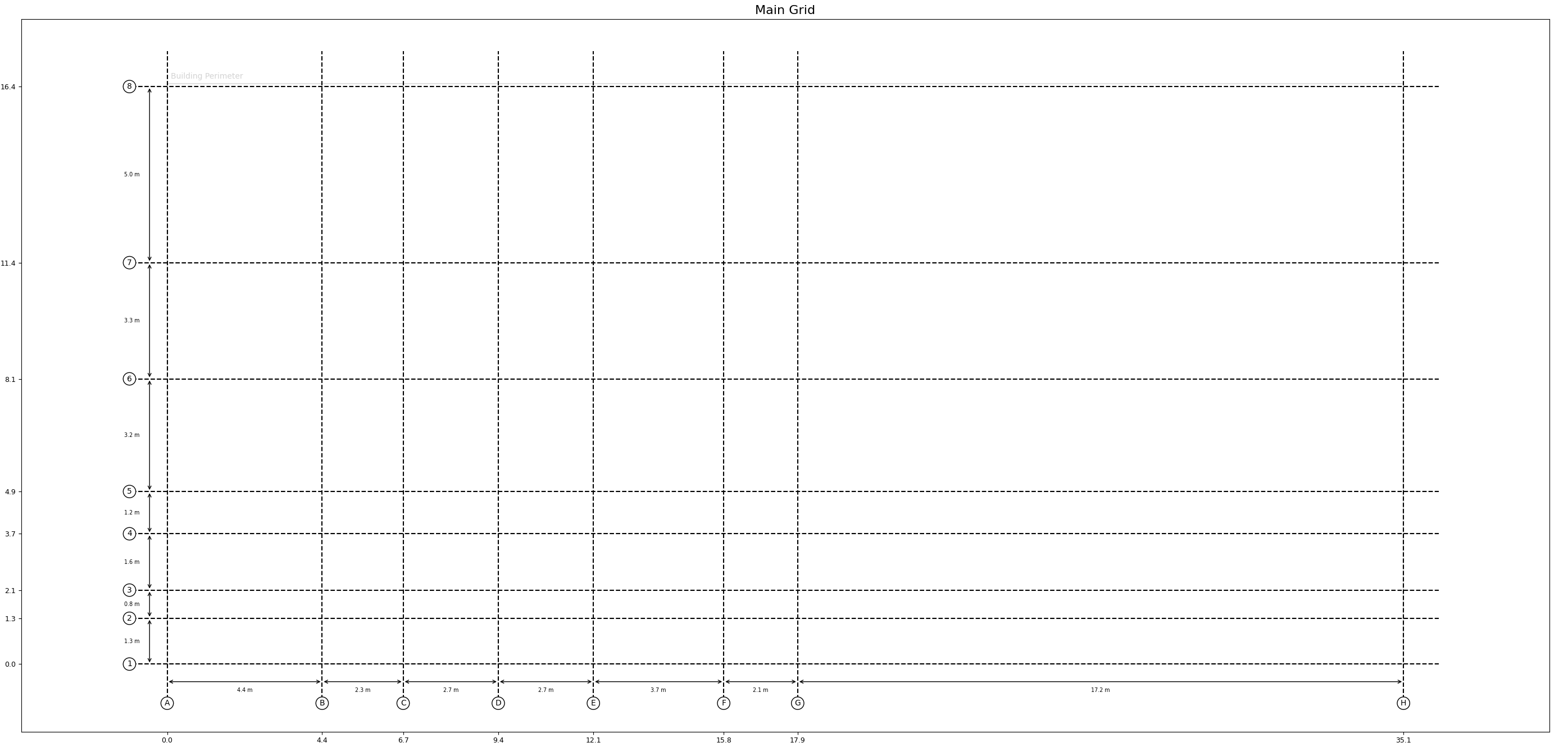
Figure 2.6 Plot of the grid.
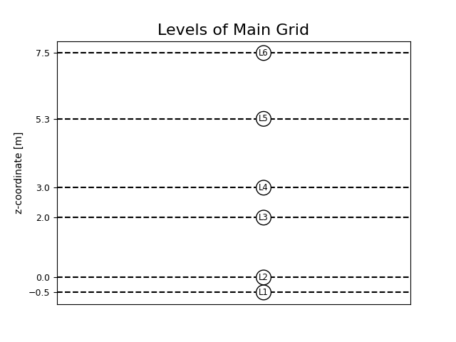
Figure 2.7 Plot of the levels in a grid.
These images contain the information that is required to continue the modelling process. The grid points can now be used to set up the geometries on each layer.
For reference on more grid functionality in the viiaPackage, have a look at the following functions:
2.5.1.4. Materials
Material properties are assigned in accordance to the given material name and analysis type. The names can be found in the Basis of Design.
2.5.1.5. Element geometries
This section will be extended soon with information on how to specify thicknesses of surface shapes and cross-sections of line shapes.
2.5.1.6. Main geometry
For VIIA the following functions have been created to assist with the creation of the shapes in the model. These use the VIIA naming convention to create materials (see Basis of Design) etc. and use the grid system. In general, usage of these functions is limited to elements of which all contour points coincide with a grid-point.
Functions to create common shapes for VIIA on grid:
To create beams:
_viia_create_beams_on_grid()To create columns:
_viia_create_columns_on_grid()To create floors:
_viia_create_floors_on_grid()To create walls:
_viia_create_walls_on_grid()
Each of these ‘on_grid’ functions requires a list of lists in which every inner list contains the relevant parameters for one instance of the respective element. An example of creating walls in batch format:
wall_list_n0 = [['H1', 'H7', 'MW-KLEI<1945', 210],
                ['H7', 'H8', 'MW-KLEI<1945', 210],
                ['C8', 'H8', 'MW-KLEI>1945', 100],
                ['C7', 'C8', 'MW-KLEI>1945', 210],
                [[6.7, 1.3], [6.7, 11.4], 'MW-KLEI<1945', 210],
                [[6.7, 1.3], 'D2', 'MW-KLEI<1945', 210],
                ['D2', 'F2', 'MW-KLEI<1945', 100],
                ['F1', 'F2', 'MW-KLEI<1945', 210],
                ['A7', 'C7', 'MW-KLEI<1945', 100],
                ['A4', 'A7', 'MW-KLEI<1945', 100],
                ['A4', 'C4', 'MW-KLEI<1945', 100],
                ['A6', [6.7, 11.4], 'MW-KLEI<1945', 100],
                ['B4', 'B6', 'MW-KLEI<1945', 100],
                ['E2', 'E6', 'MW-KLEI<1945', 100],
                ['E5', 'G5', 'MW-KLEI<1945', 100],
                ['F2', 'F6', 'MW-KLEI<1945', 100],
                ['F3', 'G3', 'MW-KLEI<1945', 100],
                ['G1', 'G3', 'MW-KLEI<1945', 100],
                ['G3', 'G5', 'MW-KLEI<1945', 100],
                ['G5', 'G6', 'MW-KLEI<1945', 100],
                [[6.7, 11.4], 'G6', 'MW-KLEI<1945', 100],
                ['F1', 'H1', 'MW-KLEI<1945', 100]]

n0_walls = project.viia_create_walls_on_grid(layer='N0', z_bottom=grid['L2'],
    z_top=grid['L4'], wall_list=wall_list_n0)
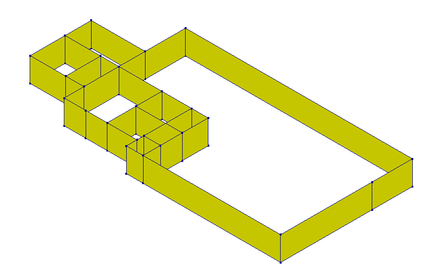
Figure 2.8 Example use of viia_create_walls_on_grid.
The wall sub-list contains the starting gridpoint or starting coordinates, the end gridpoint or end coordinates,
material and geometry going from left to right. All functions to create shapes require a layer object/name as input.
When done so, created shapes are automatically added to the provided layer as well as supplied with the lowest available
ID number. For _viia_create_walls_on_grid() specifically, the bottom and top
level of the walls needs to be specified as well.
An example of creating floors in batch format:
floor_list_n1 = [[[6.7, 1.3], 'E2', 'E6', [6.7, 11.4], 'LIN-HBV-PLANKEN-0.02-0.070-0.200-0.610', 0, 'y'],
                 ['E2', 'F2', 'F5', 'E5', 'LIN-HBV-PLANKEN-0.02-0.038-0.138-0.610', 0, 'y'],
                 ['E5', 'F5', 'F6', 'E6', 'LIN-HBV-PLANKEN-0.02-0.038-0.138-0.610', 0, 'y'],
                 ['F2', 'G2', 'G3', 'F3', 'LIN-HBV-PLANKEN-0.02-0.038-0.138-0.610', 0, 'y'],
                 ['F3', 'G3', 'G5', 'F5', 'LIN-HBV-PLANKEN-0.02-0.038-0.138-0.610', 0, 'y'],
                 ['F5', 'G5', 'G6', 'F6', 'LIN-HBV-PLANKEN-0.02-0.038-0.138-0.610', 0, 'x'],
                 [[0.0, 3.7], [4.4, 3.7], [4.4, 8.1], [0.0, 8.1], 'LIN-HBV-PLANKEN-0.02-0.060-0.110-0.800', 0, 'x'],
                 ['B4', 'C4', 'C6', 'B6', 'LIN-HBV-PLANKEN-0.02-0.060-0.110-0.800', 0, [1, 1, 0]],
                 ['A6', 'C6', 'C7', 'A7', 'LIN-HBV-PLANKEN-0.02-0.060-0.110-0.800', 0, [1, 1, 0]]]

n1_floors = project.viia_create_floors_on_grid(layer='N1', z_coordinate=grid['L4'],
    floor_list=floor_list_n1)
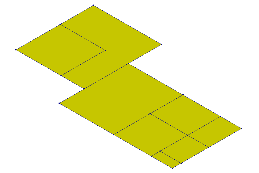
Figure 2.9 Example use of viia_create_floors_on_grid.
The floor sub-list represent the gridpoints or coordinates of the perimeter of the floor, followed by the material,
geometry and (optional) local x-axis direction. Note that any number of perimeter gridpoints may be given to create more
complex floors. Besides the layer _viia_create_floors_on_grid() requires one
level as an input which is the level at which the floors are created.
Note
For NPR9998:2020 make sure to create single span floors for timber floors with joists and planks. The material properties of those floors depend on the length of the joist and the lengths of the planks (width of the floor).
Warning
For timber floors with joists and planks the properties are detemined based on the spanning direction. Updating the local axis through the _update_local_x_axis() method will not update the properties and should therefore not be used for this floortype!
An example of creating beams in batch format:
n1_beams_list = [['B1', [6.7, 0.0], h_columns, 'LIN-HOUT', '300x300'],
                 ['D1', 'E1', h_columns, 'LIN-HOUT', '300x300'],
                 [[4.4, 2.1], [6.7, 2.1], h_columns, 'LIN-HOUT', '300x300'],
                 ['D3', 'E3', h_columns, 'LIN-HOUT', '300x300']]
n1_beams = project.viia_create_beams_on_grid(layer='N1', beam_list=n1_beams_list, grid=column_grid)
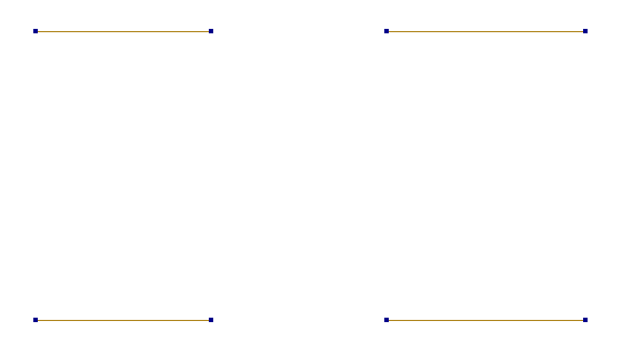
Figure 2.10 Example use of viia_create_beams_on_grid.
The first and second column of the beam_list represent the starting and ending gridpoints of the beams respectively. Coordinates can also be written instead of gridpoints. What follows from left to right is the height at which the beams are created, their material and geometry. Additionally, a grid other than the main grid is given as input. This functionality is also available for all other batch functions.
An example of creating columns in batch format:
column_list_n0 = [['A2', grid['L1'], grid['L2'], 'LIN-HOUT', '600x600'],
                  ['B1', grid['L1'], grid['L2'], 'LIN-HOUT', '600x600'],
                  [[6.7, 0.0], grid['L1'], grid['L2'], 'LIN-HOUT', '600x600'],
                  ['D1', grid['L1'], grid['L2'], 'LIN-HOUT', '600x600'],
                  ['E1', grid['L1'], grid['L2'], 'LIN-HOUT', '600x600'],
                  ['F1', grid['L1'], grid['L2'], 'LIN-HOUT', '600x600'],
                  [[0.0, 2.1], grid['L1'], grid['L2'], 'LIN-HOUT', '600x600'],
                  ['B3', grid['L1'], grid['L2'], 'LIN-HOUT', '600x600'],
                  [[6.7, 2.1], grid['L1'], grid['L2'], 'LIN-HOUT', '600x600'],
                  ['D3', grid['L1'], grid['L2'], 'LIN-HOUT', '600x600'],
                  ['E3', grid['L1'], grid['L2'], 'LIN-HOUT', '600x600'],
                  ['F3', grid['L1'], grid['L2'], 'LIN-HOUT', '600x600']]

columns_n0 = project.viia_create_columns_on_grid(layer='N0', column_list=column_list_n0,
    grid=column_grid)
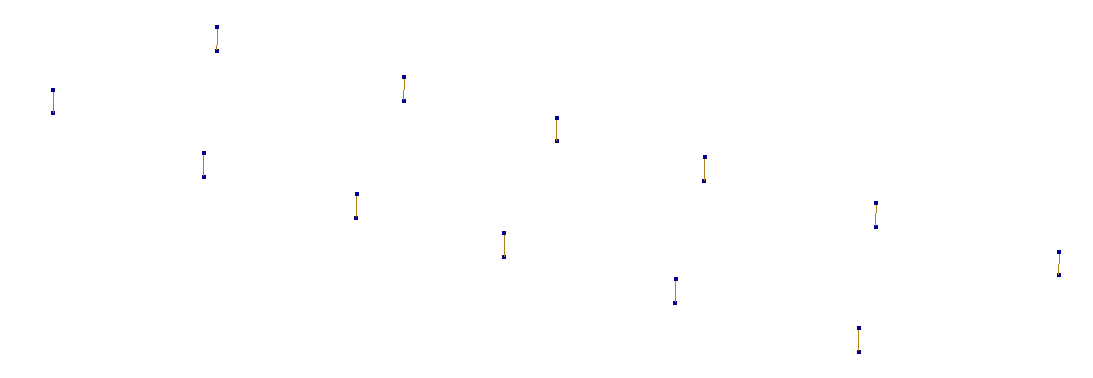
Figure 2.11 Example use of viia_create_columns_on_grid.
For _viia_create_columns_on_grid() the sub-list represents the location of the
column, the bottom and top level, material and geometry.
For beams and columns, some examples of the most commonly used profiles from viiaPackage are given in table below. For all available profiles, please refer to the file viiapackage\VIIA-Database-Profiles.json in local package location.
Profile |
shape |
Examples of profile name |
|---|---|---|
{w}x{h} |
Rectangle |
100x180, 120x200 |
R{r} or D{d} |
Circle |
R120, D160 |
HEA |
I-shape |
HEA100A, HEA120 |
HEB |
I-shape |
HEB160, HEB180 |
HEM |
I-shape |
HEM200, HEM220 |
INP |
I-shape |
INP240, INP260 |
IPE |
I-shape |
IPE300, IPE330 |
UNP |
U-shape |
UNP100, UNP260 |
UPE |
U-shape |
UPE120, UPE240 |
Additionally, some complicated profiles are also supported. Some examples are given below. For all available profiles, please refer to the file haskoning_structural\geometries\geometry_models\profile_geometries\fem_database.json in local package location.
Profile |
shape |
Examples of profile name |
|---|---|---|
RHS |
Box |
RHS100x40x2.5, RHS50x20x1.6 |
SHS |
Box |
SHS100x10, SHS100x3.6 |
CHS |
Pipe |
CHS101.6x10,CHS26.9x2.0 |
RO |
Pipe |
RO10.2x0.5, RO1016x4 |
HD |
I-shape |
HD260x114, HD400x677 |
HP |
I-shape |
HP10X42, HP305x79 |
UB |
I-shape |
UB1016x305x222, UB305x165x40 |
UC |
I-shape |
UC152x152x23, UC203x203x46 |
L |
L-shape |
L16x16x3, L45x45x4.5 |
ZIPXL |
BeamProfile |
ZIPXL_1800, ZIPXL_2400 |
HRP |
BeamProfile |
HRP500, HRP1200 |
To create shapes manually within the VIIA scope the following functions are available. With these you can create shapes that cannot be :
To create beams:
_viia_create_beam()To create columns:
_viia_create_column()To create floors:
_viia_create_floor()To create roofs:
_viia_create_roof()To create walls:
_viia_create_wall()To create foundation strips:
_viia_create_fstrip()
To create the geometries and materials use the functions (in normal workflow you don’t use those):
To create materials:
_viia_create_material()To create geometries:
_viia_create_geometry()
Roof elements or other irregular elements that do not fit on the grid need to be created manually. An example of creating a roof:
roof_1 = project.viia_create_roof(
    name='N2',
    material=f'LIN-HBV-PLANKEN-0.003-{b}-{h}-0.580',
    geometry=0,
    points=[[grid['H1', 'L3'],
             grid['H2', 'L4']],
             [0.5 * (column_grid['E'] + column_grid['F']), 0.5*(grid['1'] + grid['8']), roof_barn],
             [grid['C'], 0.5*(grid['1'] + grid['8']), roof_barn],
             grid['C2', 'L4'],
             grid['F2', 'L4'],
             grid['F1', 'L3']]],
    element_x_axis='vertical')
Note the usage of the grid to supply the coordinate points, and that in this case roof_barn is a float.
An example of creating a column:
column = project.viia_create_column(
    name='N2',
    material='LIN-HOUT',
    geometry='250x250',
    points=[grid['G7', 'L1'], [*grid['G7'], roof_2]])
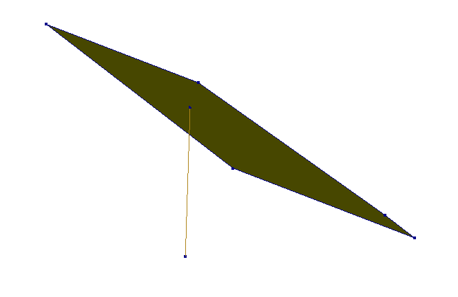
Figure 2.12 Example use of viia_create_roof and viia_create_column making use of projection.
In this example a single column is generated. Note that for the second gridpoint the z-coordinate is replaced with roof_2 (a roof shape). When this is done, the replaced coordinate is determined by a projection on the plane of the given element while the other coordinates remain unchanged. Smart use of this functionality lessens the need to calculate coordinates manually.
Warning
Only 2D elements can be used and at most one dimension per coordinate can be replaced with an element.
2.5.1.7. Foundation walls and strips
The modelling of the supports (shallow foundation or pile foundation) is not part of the modelscript. These are modelled in the mainscript. The structural foundation shapes that connect to these are modelled in the modelscript. This consists of foundation strips and foundation beams. In case a geotechnical assessment is required, the lay-out of the foundation should be discussed with the geotechnical engineer (sketch where to apply shallow foundations, or locate the piles in a pile plan).
To assist in the creation of strip foundations
viia_create_foundation_walls_and_strips() is made available. This
function creates foundation walls and strips directly below a set of walls and automatically properly connects them. See
an example of its usage below:
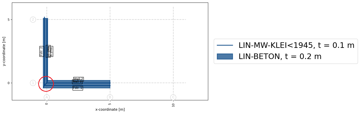
project.viia_create_foundation_walls_and_strips(
    walls=n0_walls,
    strip_material='LIN-BETON',
    strip_width=450,
    strip_thickness=150,
    foundation_depth=grid['L1'],
    adjust_strips=True)
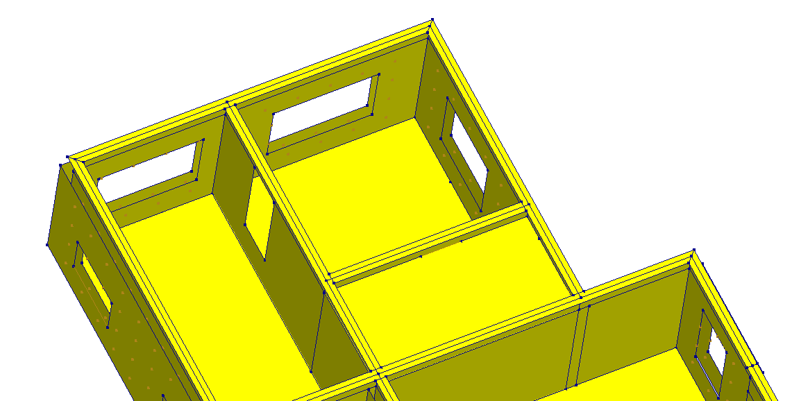
Figure 2.13 Example use of viia_create_foundation_walls_and_strips (view from beneath the model).
In this case the dimensions of the equivalent foundation are directly given. Alternatively one could supply the actual strip dimensions which are then converted to the equivalent dimensions.
project.viia_create_foundation_walls_and_strips(
    walls=n0_walls,
    stepped_foundation_strip_extensions=[60, 50, 25, 100],
    stepped_foundation_strip_heights=[50, 70, 100, 50],
    foundation_depth=grid['L1'],
    adjust_strips=True)
Optionally, when a cavity wall is resting on a solid foundation wall, an additional input parameter cavity_extension can be given in the unit of [mm]. This parameter represents the height of the cavity wall part, which is the downward extension of the ground floor cavity wall, in the foundation level. By default, the value of it is 0, which means the cavity wall ends at ground floor level, and below is a solid foundation wall. This parameter is relevant to the calculation of the thickness of the foundation wall. The figure below shows a real example of when this parameter is needed for a more realistic model.
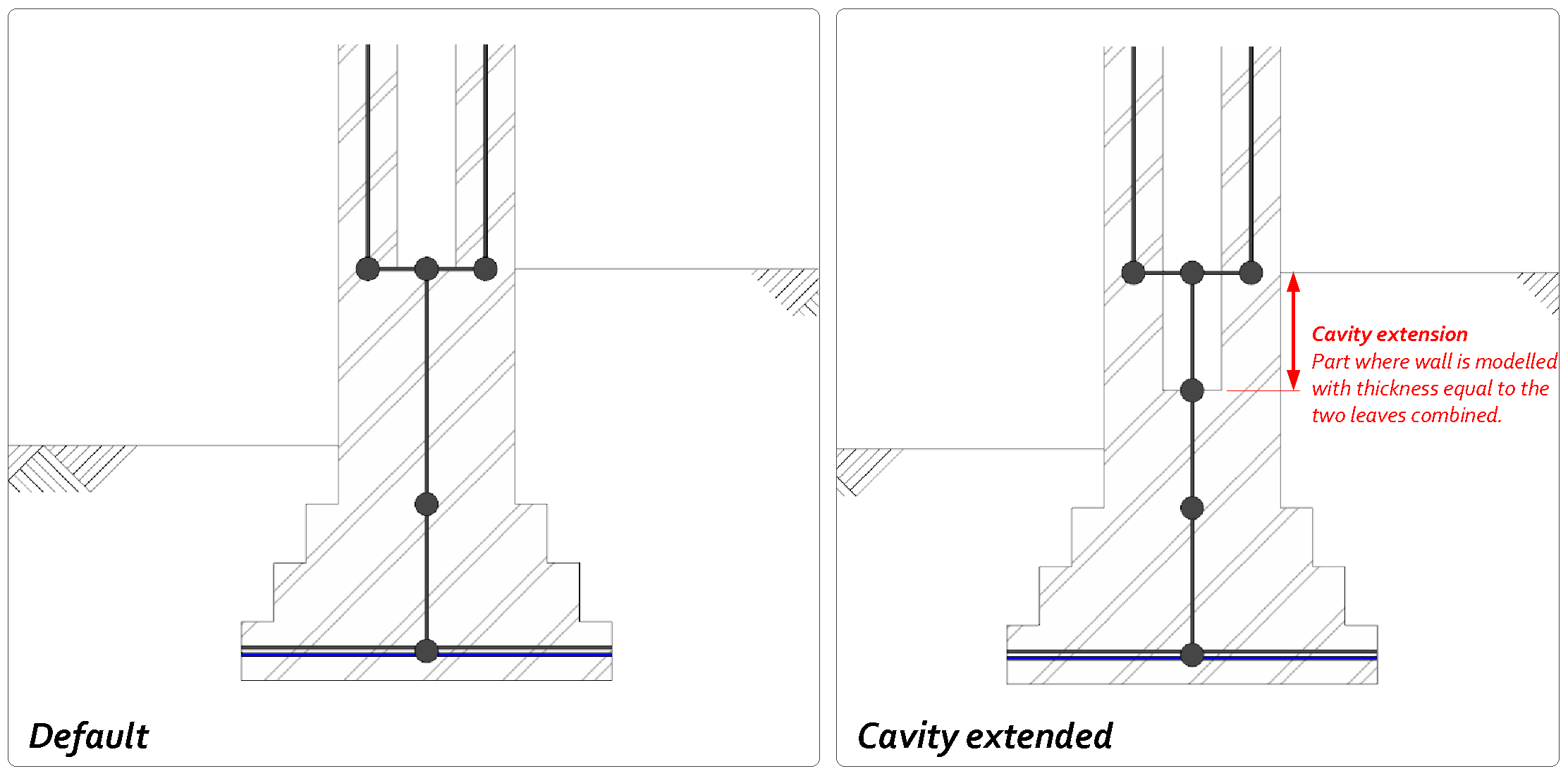
Figure 2.14 Example use of viia_create_foundation_walls_and_strips for cavity wall extension.
Warning
Automatic connection of foundation strips is limited to T-connections (in which the upper part of the ‘T’ is continuous), perpendicular directions and corner connections with an arbitrary angle. Other type of connections might not be available and require manual inputs.
With the functions outlined in these two chapters the main geometry of a structure can be set up. In a later step (6) this geometry will be edited as to include more details and become more accurate.
For further reading on modelling foundations we refer to the howto-guide on foundations: How to create shallow foundations.
2.5.1.8. Roof modelling
The roof can be modelled in the way the floors are created. There are however convenient functions available to create roofs for standard situations. How to apply these functions is described in the docstrings of the functions:
In objects that have (parts) of the roof with materials that do not provide for diaphragm capacity the roof (rafters and purlins) can be modelled with beams only. To later properly create the plots of the roof you need to define for these beams that they are part of the roof-beams collection. You should set specify this when creating the beam:
project.viia_create_beam(name='N1', material='LIN-HOUT', geometry='D100', points=points, is_roof_beam=True)
In the plots created for the model, you check if the roof is created correctly.
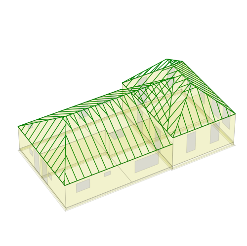
Figure 2.15 3D visualisation of the roof structure.
2.5.1.9. Interactive modelling
Once the grid is defined, the interactive modelling could be used to generate the syntax for the shapes by using matplotlib. This tool is explained in the how to guide: How to use the interactive modelling tool. The tool provides the syntax for the modelscript, including grid-point input.
2.5.1.10. Other ways to create the analysis model
If a previous model has been analysed in other software, the file can be converted and then imported. If a REVIT model is present this can be converted too, using the DataFusr platform. Also Sketch-up and Grasshopper procedures are available. These methods are not described in this document and should only be used if the user is familiar with them and is able to apply the VIIA workflow.
2.5.2. Structural Schematisation
When starting a model for an object, two issues must be taken into account right from the start. First, how accurate should the model be and secondly what accuracy is desired for the end situation of the final model that will be analysed.
An unambiguous (most simple possible) model must be set up in this phase in order to prevent numerical instability in the analysis later on. This step requires to reflect on the draft model setup in the previous step. Look at the model and consider all components. For example: remove the non-structural elements where failure is allowed. Also pay attention to openings close to borders of the walls. Where there is an opening connecting to a continuous wall, it is not necessary to model a slender wall with a width of half a wall thickness. Considerations should as well be given for rounding; for example, a floor spanning 7.185m can be modelled with a dimension of 7.2m. All updates to the model need to be done in the modelscript (and not in mainscript used for analyses).
After loading the modelscript in the selected software (DIANA or ABAQUS) the mesh can be generated. From the loaded model it is relevant to check if all the surfaces elements such as floors and walls are in the correct plane. Since a lot is automated within the viiaPackage, the possibility of mistakes is reduced but still it is important to check the assignments of materials, the thicknesses of the walls, etc.
Note
Load bearing slender piers with a width of less than 25cm and a shape ratio of at least 3 (height/width) should be modeled as pinned linear columns. This means that the elements will not carry any lateral load, only vertical, and the failure mechanism is to be rocking.
Note
Slender piers, as shown in the figure below, should NOT be modelled when the width of the pier is smaller than 2x the thickness of the walls connecting it (simplify as in the image).
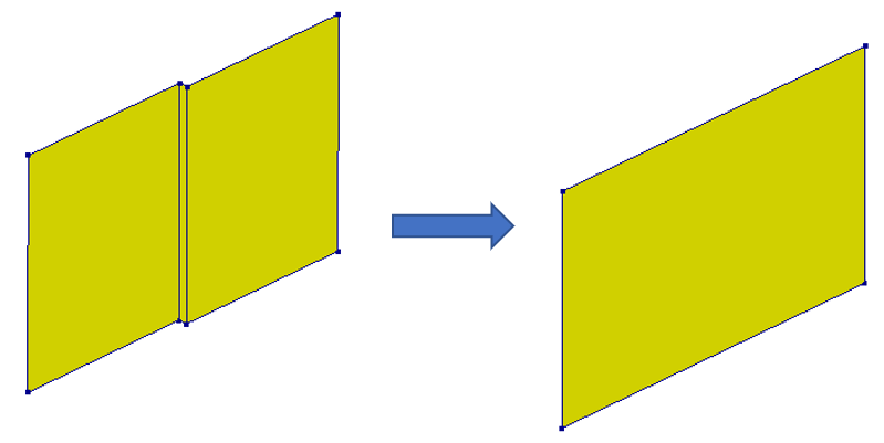
Figure 2.16 Small pier, between two closely located paralel walls.
Note
Slender piers, as shown in the figure below, should NOT be modelled when the following statements are met: the width of the pier is smaller than 25cm, the width of the pier is smaller than 2 times the walls connecting it, and the area of the pier is less than 10% of area of the connecting wall.
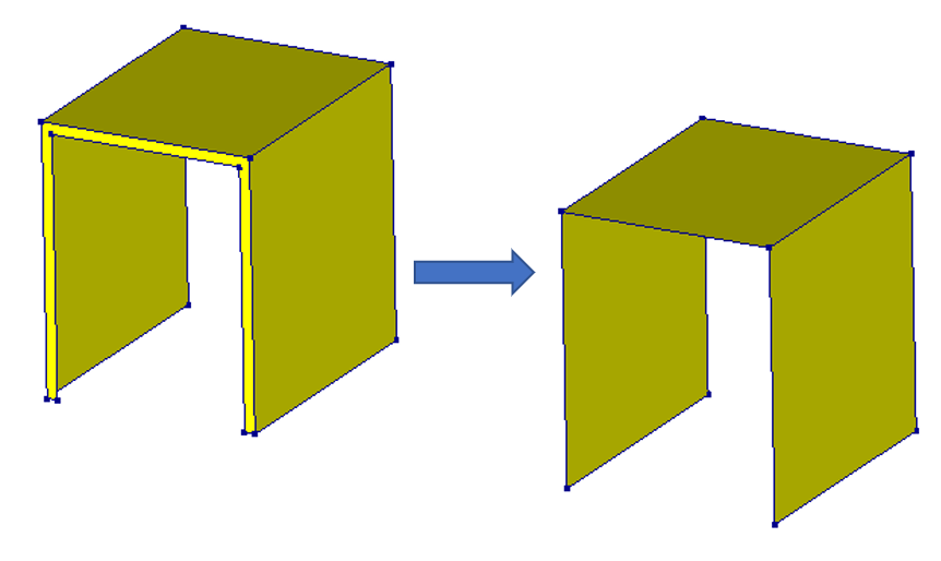
Figure 2.17 Another small pier, located at opening.
In order to have an idea about how the model looks like, before importing the script in DIANA or ABAQUS, it is possible
to create a plot. The 3rd party module matplotlib should be installed for this function (this is done automatically if
you used the prescribed installation procedure). A graphical representation of the object can be obtained with the
function viia_plot_layers(). Additional settings can provide more detailed plots to
check your model more efficiently in your python editor. Other functions that can be useful when checking the setup of
the model are viia_plot_grid() and
viia_create_plots(). By adjusting the input you can generate the plots you want. Here
we show some useful examples.
project.viia_plot_layers('N0')
This function will create the plots of all shape-types in the layer N0 (walls, columns and floors) in a 2D plan view. The main grid is included. The figures are stored in a sub-folder of your working folder called ‘Modelling Pictures’. By default the picture is shown, you can suppress by providing input show=False. To only generate the plot with the wall ID indicated in 2D plan (including dimensions) you can use the following:
project.viia_plot_layers('N0', '2D', 'walls')
Which will generate the following figure:
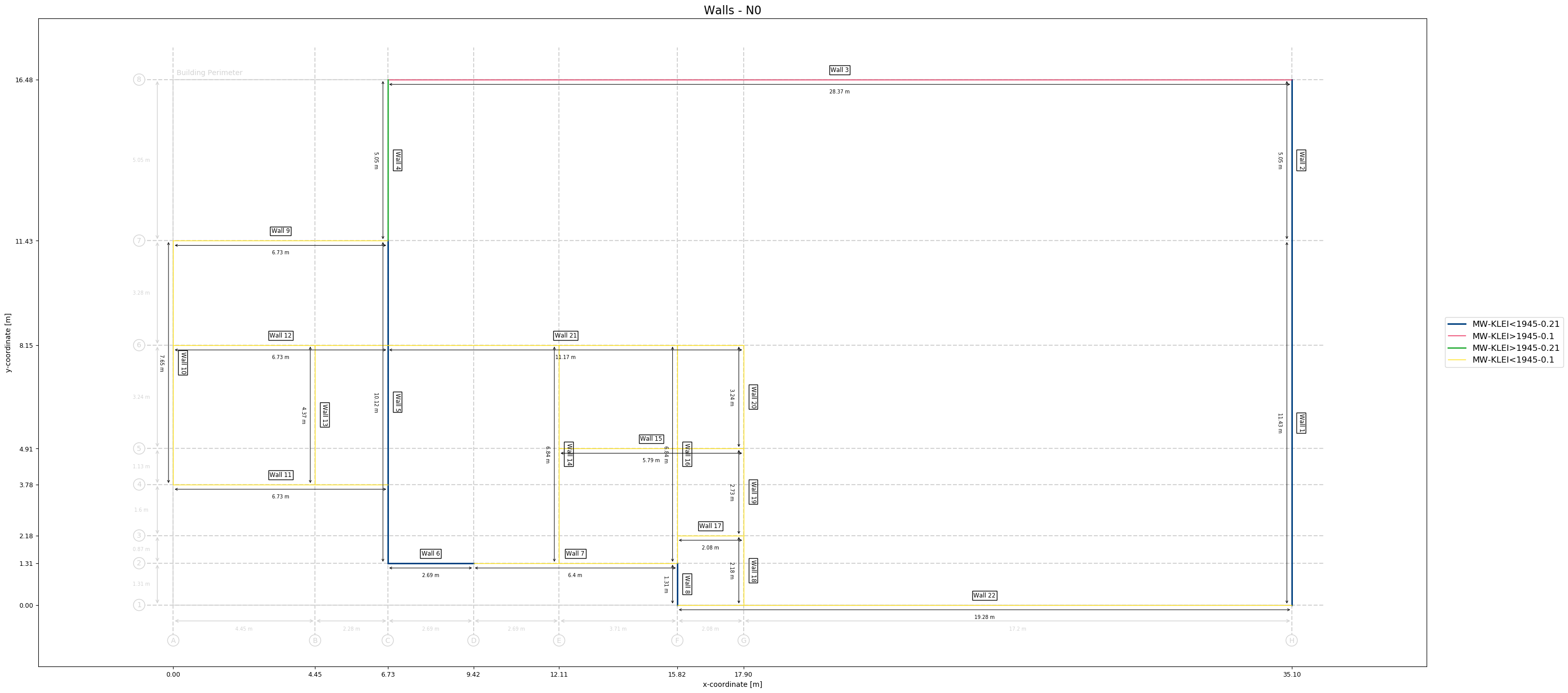
Figure 2.18 Wall ID indicated on 2D plan.
You can generate a 3D view of the layer with the following code:
project.viia_plot_layers('N0', '3D')
This will generate a picture of the layer in 3D.
Which will generate the following figure:
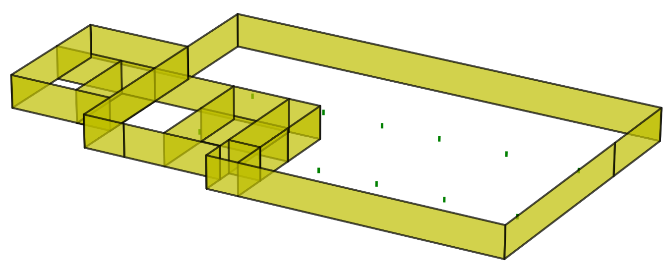
Figure 2.19 3D view of the layer.
Note
Always check the plots in the reports that are delivered to the client. Check the quality of the plot, for example if the labels or dimensions are properly readable or check if all shapes are present. It might be that you need to manually improve.
2.6. Step 5: Editing geometry
Once the initial model is set, the geometry can be further elaborated with the help of functions. It is preferred that these adjustments are done before the model is created in DIANA, because the python-memory is what is used in the script; moreover, it takes a lot of time in DIANA to create elements, to remove and to create new ones. Also once the model is created in DIANA, not all functions are available to adjust geometry.
This step contains an explanation on the functions that are available to adjust the model for the specific needs in the analysis. Some of the examples shown in this section can also be found in the example modelscript:
2.6.1. Adding openings
Openings in walls and roofs are measured while performing the inspection. We have made arrangements with the inspectors
to indicate the dimensions of the openings in the walls and roofs in a specific manner in the inspection report. These
values can than be used in the function viia_add_openings(). The following
input shows adding two openinsg to the wall. The starting point of the wall or roof is the point that was defined first
while creating. If the received values for the openings are from the other side of the wall, you can set the flip input
to True, then the functionality is applied in the opposite direction. For roofs you might need to update the start
definition if it does not work for your model to flip.
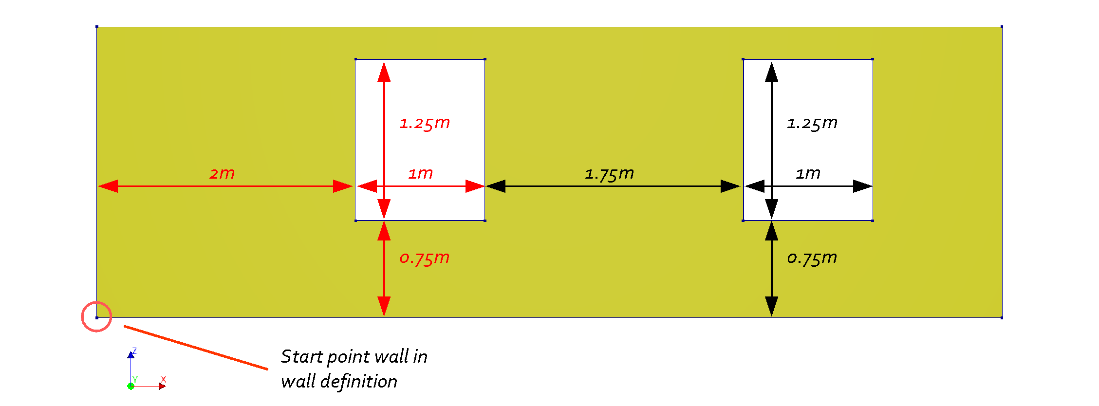
Figure 2.20 Example wall with 2 openings defined.
# Adding openings to surface shapes
opening_list = [
    [wall, [[2.0, 1.0, 0.75, 1.25], [1.75, 1.0, 0.75, 1.25]]
project.viia_add_openings(opening_data_list=n0_wall_opening_list)
It is also possible to add an opening in the create function of the wall. In that case you need to provide the coordinates in the global system. But for readability of the modelscript it is advised to use this function.
When the openings should be applied to a roof, you can use the function
viia_add_roof_openings(). The same approach to providing the dimensions as the
function to apply openings in walls has been agreed with the inspectors. For flat roofs you should use the
viia_add_floor_openings instead.
For floors the function viia_add_floor_openings() is
available. The following example will generate two openings in a floor. In the figure below, the dimensions are shown.
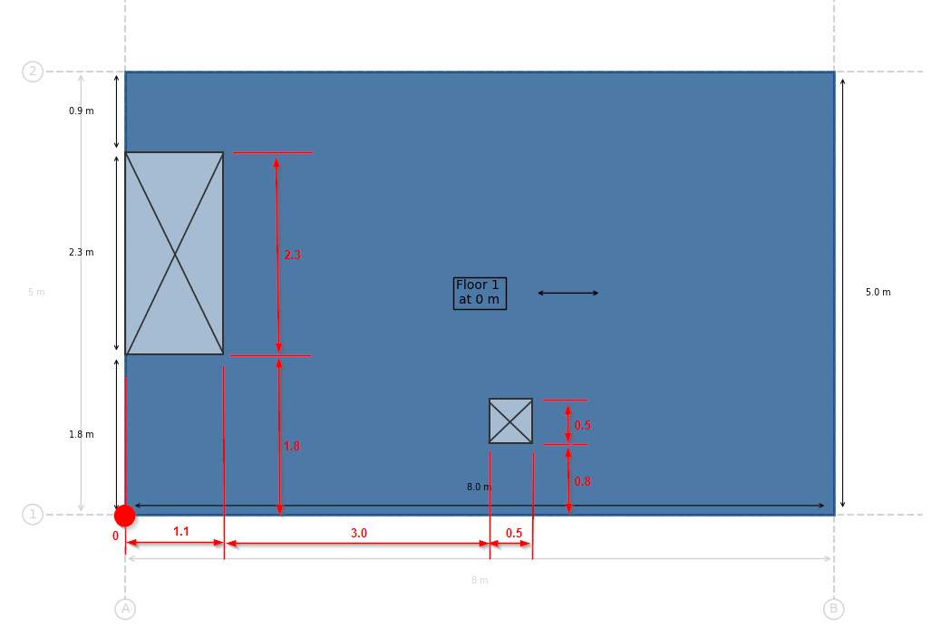
Figure 2.21 Example floor with 2 openings defined.
grid = project.viia_create_orthogonal_grid([[0, 8], [0, 5]])
project.viia_create_levels([0])
floor = project.viia_create_floors_on_grid(
    layer='N0', z_coordinate=grid['L1'], floor_list=[['A1', 'B1', 'B2', 'A2', 'LIN-KPV-150', 0]])[0]
project.viia_add_floor_openings(floor=floor, opening_list=[[0, 1.1, 1.8, 2.3], [3, 0.5, 0.8, 0.5]])
The function uses the direction of the local x-axis. The starting point is by default the first point that is used to define the floor (in the example this is point ‘A1’). For more complex openings you can specify any point and any direction. For both the projection on the plane of the floor is used. Also the flip parameter is present, which flips the default or provided direction. In the following example a rotated opening is created on the floor of the example.
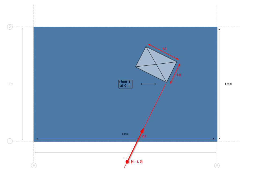
Figure 2.22 Example floor with rotated opening defined.
project.viia_add_floor_openings(
    floor=floor, opening_list=[[4, 1, 0, 1.5]], starting_point=[4, -1, 0], direction=[1, 2, 0])
The functionality to add openings to the floor, is only available for horizontal floors.
2.6.2. Beams in floors or roofs
Rafters, purlins and floor beams can easily be created using the function
_viia_create_beams_on_grid_in_shape(). This function takes as input a layer, a
grid, a list of gridlines, a shape, and the material and geometry of the beams. The function creates beams on all the
given gridlines and makes sure they are contained in the given shape. The beams can be created as follows:
project.viia_create_beams_on_grid_in_shape(
    layer='N2', grid=house_roof_grid, gridlines=['A', 'B', 'C', 'D', 'E'], shape=roof_4,
    material='LIN-HOUT', geometry='65x115)
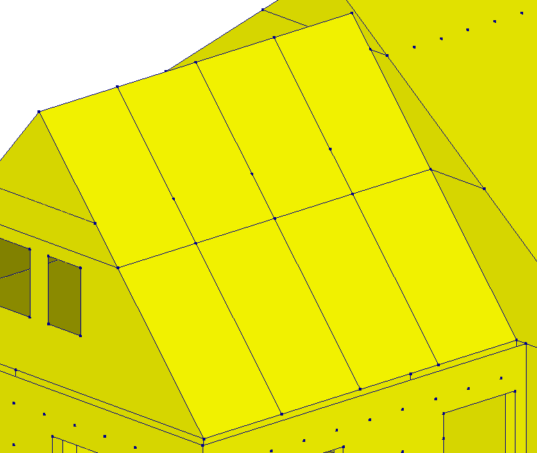
Figure 2.23 Application of rafters on gridlines in a roof using viia_create_beams_on_grid_in_shape.
Note
If there are openings in the roofs, the beam will not be cut by the opening if the gridlines goes through the opening.
2.6.3. Collar ties
Collar ties can also be created easily using the gridlines with the function
viia_create_collar_ties_on_grid(). This functions takes the same input as
above, except the shapes argument takes a list of two roofs, and there are also two additional arguments to define the
height at which the collar ties are created. The first one is beam height, which can either be a number or a level
object. If it’s a level object, then the collar ties are created at the elevation of the level. If it’s a number, then
they are created at that height but measured from the elevation of the last input, which is floor_level, which can also
be a number or a level object. The level objects can also be passed as strings, where the string is the name of the
level, and the level has to be defined in the given grid. The beams can be created as follows:
project.viia_create_collar_ties_on_grid(
    layer='N2', grid=house_roof_grid, gridlines=['A', 'B', 'C', 'D', 'E'], shapes=[roof_4, roof_5],
    beam_height=2.95, floor_level=3.02, material='LIN-HOUT', geometry='65x115)
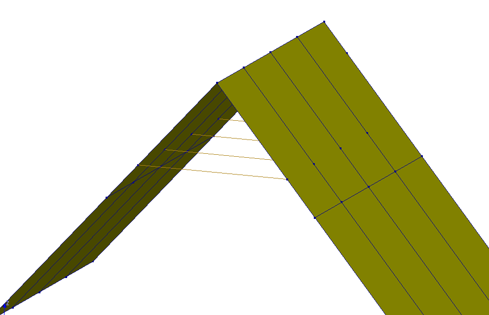
Figure 2.24 Application of collar ties on gridlines using viia_create_collar_ties_on_grid.
2.6.4. Cavity walls and wall ties
In NLTH both walls of the cavity walls and wall ties, are to be explicitly modelled. Cavity walls and wall ties can be
created using the function viia_create_cavity_wall_ties(). This
function should be used when all walls and floors have been modelled. The number of wall ties depend on the age of the
building and applied Basis of Design.
Note
In the NLPO analysis type, the outer cavity wall leaf was not modelled, but the mass of the outer leaf was
added on the foundation, using a line load. This line load can be created with the function
viia_add_outer_leaf_wall_line_load().
The standard approach to apply cavity walls and its wall ties is to first create only the inner leaf of the walls. Then the list functionality for cavity walls can be used, in its most basic form, as follows:
project.viia_create_cavity_wall_ties_from_list(
        cavity_wall_list=['wall_1', 'wall_2', 'wall_3'], cavity=0.1)
This will create outer leafs, cavity wall ties and dummy plates for all the walls in the cavity wall list, with a cavity of 0.1m. The rest of the arguments will have their default value. Outer leafs are connected in the corners, and wall ties that are close to edges and openings are snapped to avoid issues with the mesh.
When using this function, the edges of the cavity walls are also merged with other cavity walls created using this function. Besides the list, the settings that are applied to all new cavity walls must be passed. Each entry in the input list is either a string representing a wall, a wall object, or a list that contains a wall object/string as well as additional settings in a dictionary. If a dictionary of options are passed here, the settings defined for all walls are overriden. Below is an example of how cavity walls and ties can be created for many walls simultaneously. The string representation of the wall must be ‘wall’ followed by underscore and the ID of the wall.
project.viia_create_cavity_wall_ties_from_list(
    cavity_wall_list=['wall_1', ['wall_2', {'cavity': 0.2}], 'wall_3' .. etc.], cavity=0.1)
This creates all outer leafs, cavity wall ties and dummy plates with a cavity of 0.1m, except for wall with ID 2 the cavity will be 0.2m. Note that this can be done for all keyword arguments described in the input parameters in the docstring of the function. Input may therefore also look something like this:
project.viia_create_cavity_wall_ties_from_list(
    cavity_wall_list=[
        ['wall_1', {'cavity': 0.18, 'wall_tie_distance': 0.7, 'outer_wall_thickness': 150}],
        ['wall_2', {'flip': True}],
        'wall_3', 'wall_4',
        ['wall_5', {'edge_distance': 0.3, 'offset_vertical': 0.1, 'flip': True}]
    ],
    cavity = 0.3,
    dummy_plates=False,
    offset_base=0.25,
    snap_to_contour=False)
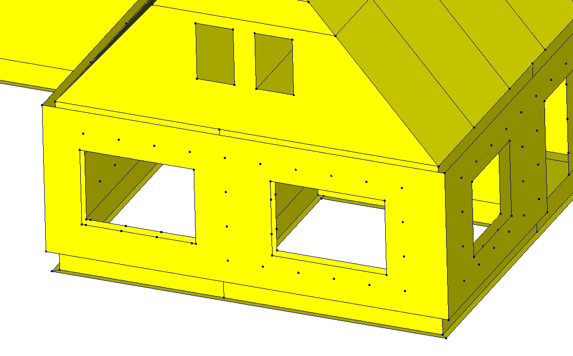
Figure 2.25 Application of cavity walls and wall ties using function viia_create_cavity_wall_ties_from_list.
Note
In general, the geometry of the cavity walls is automatically corrected when using the function
viia_create_cavity_wall_ties_from_list(), but there could be exceptions.
E.g. no more than two cavity walls should meet in one location, and cavity walls should not cross each other.
There are two ways to update the cavity walls’ geometry in order to merge them if they are not merged automatically:
Preferably, by moving the respective lines to fill the gap,
wall.contour.move_line_only(line=cavity_wall_1.contour.lines[1], vector=[0.17, 0, 0])
wall.contour.move_line_only(line=cavity_wall_1.contour.lines[3], vector=[-0.17, 0, 0])
Another option to connect the outer leafs is to update the contour:
wall.contour = project.create_polyline(point_list=[
    [21.85, 1.65, 3.05], [21.85, 9.95, 3.05], [21.85, 9.95, 0], [21.85, 1.65, 0]])
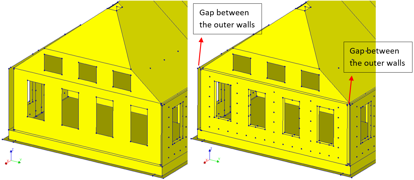
Figure 2.26 Application of cavity wall and wall ties in model with function viia_create_cavity_wall_ties, before adjusting cavity wall geometries.
Figure 2.27 Geometry update of the outer cavity wall to connect the outer walls.
Sometimes, the position of the wall ties can create problems. For example, a cavity wall tie is so close to an
opening which creates bad-shaped elements during the mesh stage. The function
viia_move_cavity_wall_tie() can be used to move a wall tie. It
takes the wall tie object as input, as well as the new coordinates. To get the correct wall tie you can use the
viia_get_connection() function to search for it based on
name, ID or by location (point).
wall_tie = project.viia_get_connection(point=[21.85, 5.32, 0.50])
project.viia_move_cavity_wall_tie(cavity_wall_tie=wall_tie, new_coordinates=[21.85, 5.32, 0.80])
Note that only the inner leaf coordinates need to be provided. The function will project the coordinates to the outer leaf automatically
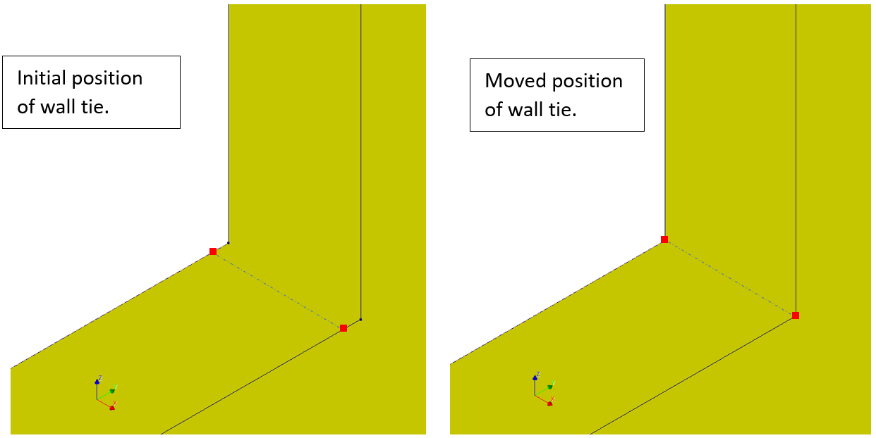
Figure 2.28 Initial and moved position of the cavity wall tie with function viia_move_cavity_wall_tie.
It is also possible to remove a cavity wall tie. To do this, the function
viia_remove_cavity_wall_tie() is available.
This function only takes the wall tie object as input:
project.viia_remove_cavity_wall_tie(wall_tie_1)
This will remove the Spring object that describes the tie from the collections. It will also remove the internal points on the wall if they are no longer used by any other shape geometries. The node objects are also removed if they are not used any longer.
In case of cavity walls without any functioning walls ties, it is possible to model the outer leaf. In these cases some
sort of support is still needed at the top of the outer leaf to prevent it from cantilevering out-of-plane. The function
viia_create_wall_ties_on_line() can be used. The function takes
the inner and outer leaf as input, as well as a list of lines along where the ties should be applied. Other parameters
are optional and are related with the spacing of the wall ties and snapping to nearby points. Below is an example of how
the function can be used to create wall ties along the upper edges of cavity walls:
project.viia_create_wall_ties_on_line(
    inner_leaf=inner_leaf,
    outer_leaf=outer_leaf,
    lines=inner_leaf.get_top_edges()),
    wall_tie_distance=0.40)
If the lines are not on the top edge there are several methods to get the relevant line objects. For instance, all lines between the two points [[0, 0, 0], [1, 0, 0]] can be found with the next code:
lines = project.find_lines_in_line(line=[[0, 0, 0], [1, 0, 0]], lines=inner_leaf.get_lines(), check_coverage=True)
2.6.5. Lintels
The function viia_create_lintel() can be used to create lintels on top of a
given opening and it is extended 0.1m on both side of the opening (see the figure below). Input for this function is the
wall in which the opening is located, the number of the recess, geometry of the lintel, the material and
the support length in the wall. The wall can be given as either the wall object, the name of the wall, or simply the ID
of the wall.
For example:
project.viia_create_lintel(
    wall=1,
    opening_number=1,
    lintel_material='LIN-STAAL',
    lintel_type='L100x100x10')
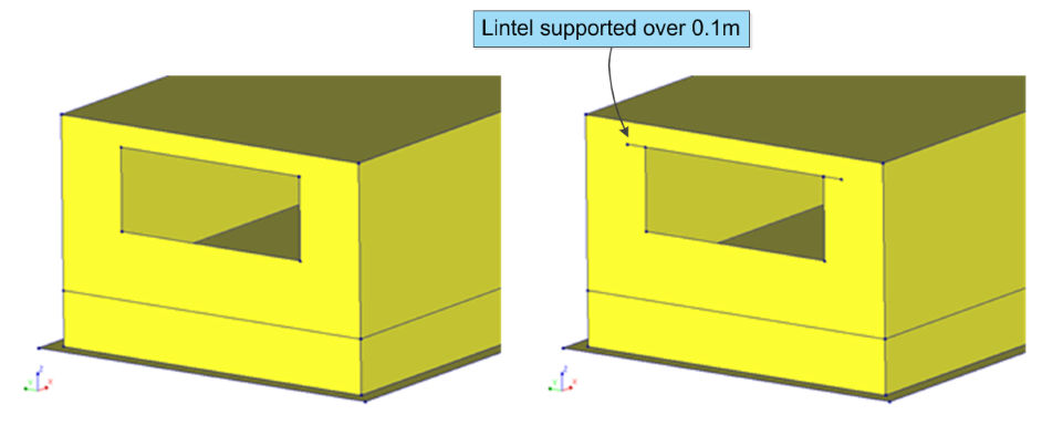
Figure 2.29 Application of lintel in model with function viia_create_lintel.
The lintels can also be created in batch if they share the same cross-section and material. The following example demonstrates application of a HEA100 profile on top of all openings in the N0 layer. Note that it skips any opening that already has a lintel (that might have been created earlier, and has the same support-length).
# Create lintels
project.viia_create_all_lintels(lintel_material='LIN-STAAL', lintel_type='HEA100', collection='N0')
When there are cavity walls present, these should be modelled first. Then when the create function for lintels is applied the inner leaf will be supported by a lintel. The outer leaf is supported on the same lintel with a dummy-plate. If you want two separate lintels set the lintel_slab input to False. In that case two lintels are generated, which are not connected.
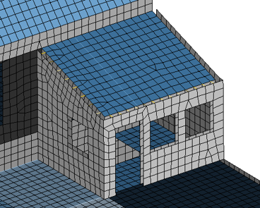
2.6.6. Roof structures
Complicated roof structures require careful consideration upfront. Simplify the structure as much as possible and minimise the input coordinates copied from DIANA to prevent floating point precision issues (instead use functions to calculate intersections).
2.6.6.1. Splitting and cutting surfaces
Creating walls using _viia_create_walls_on_grid() only results in rectangular
walls, and all the walls created using that function have the same height. However, many times walls are not
rectangular, or all the walls in the same layer don’t have the same height. Therefore, the split surface function can
be used to split these walls using other surfaces, e.g. roofs. In order to cut a surface, the
split_surface() method of the surface to be cut must be called,
and the input to this function should be the tool surface that performs the cut. The tool surface splits the surface
into two surfaces, and by default in the method the surface with the lowest centroid is kept. This can be overridden by
passing other strings to the ‘keep’ argument, as shown in the examples below. The other options are ‘top’, ‘largest’,
‘smallest’, ‘left’, and ‘right’. Below are several examples of how to perform the cutting, and the figure shows before
and after:
wall_24.split_surface(roof_4, keep='largest')
wall_24.split_surface(roof_5, keep='largest')
wall_25.split_surface(roof_4)
wall_25.split_surface(roof_5)
wall_23.split_surface(roof1)
wall_23.split_surface(roof2)
wall_26.split_surface(roof1)
wall_26.split_surface(roof2)
floor_11.split_surface(roof_4, keep='largest')
floor_11.split_surface(roof_5, keep='largest')
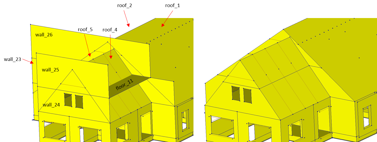
Figure 2.30 Before (left) and after (right) splitting walls and floors using roof surface.
Note
This function should be used on a trial-and-error basis, as whatever you choose to keep might not always work out the way you desire.
Note
Note that this function only changes the contour of the surface. It does not perform any adjustments of openings or to potential cavity ties that might be on the part that’s cut off.
Warning
Currently, the capabilities of this function is relatively limited. Most importantly, splitting can only
be performed when there is one intersection line, so it should be used before
_viia_connect_all_shapes(). Additionally, if the intersection line does not go
from contour to contour of the shape to be cut, then it is extended as such. This is how wall_25 can be cut by
roof_4 and roof_5.
2.6.7. Trusses
Beams can be loaded in bending. For small cross-sectional properties, these beams can have low eigenfrequencies and
therefore disturb the dynamical analysis. Often these beams are applied only to act in tension for trusses. The function
viia_truss() will switch a beam to an element that can only take axial
forces. In ABAQUS your beam will be defined with truss element (T12) and in DIANA this is called the enhanced truss
element (ENHTR3).
2.6.8. Timber frame floors modelling
If the engineer decides to model timber frame floors as sections with equivalent properties of the beams and slab,
the function viia_wooden_beam_floors() can be used.
project.viia_wooden_beam_floors(floor)
2.6.9. Chimney duct
Chimney ducts are present in the building to support the chimneys on the roof and are added to the geometrical model to account for the capacity of ducts. The addition of vertical chimney ducts to the model is straightforward, however, the modelling of tampered and inclined chimney ducts should be discussed with the lead engineer.
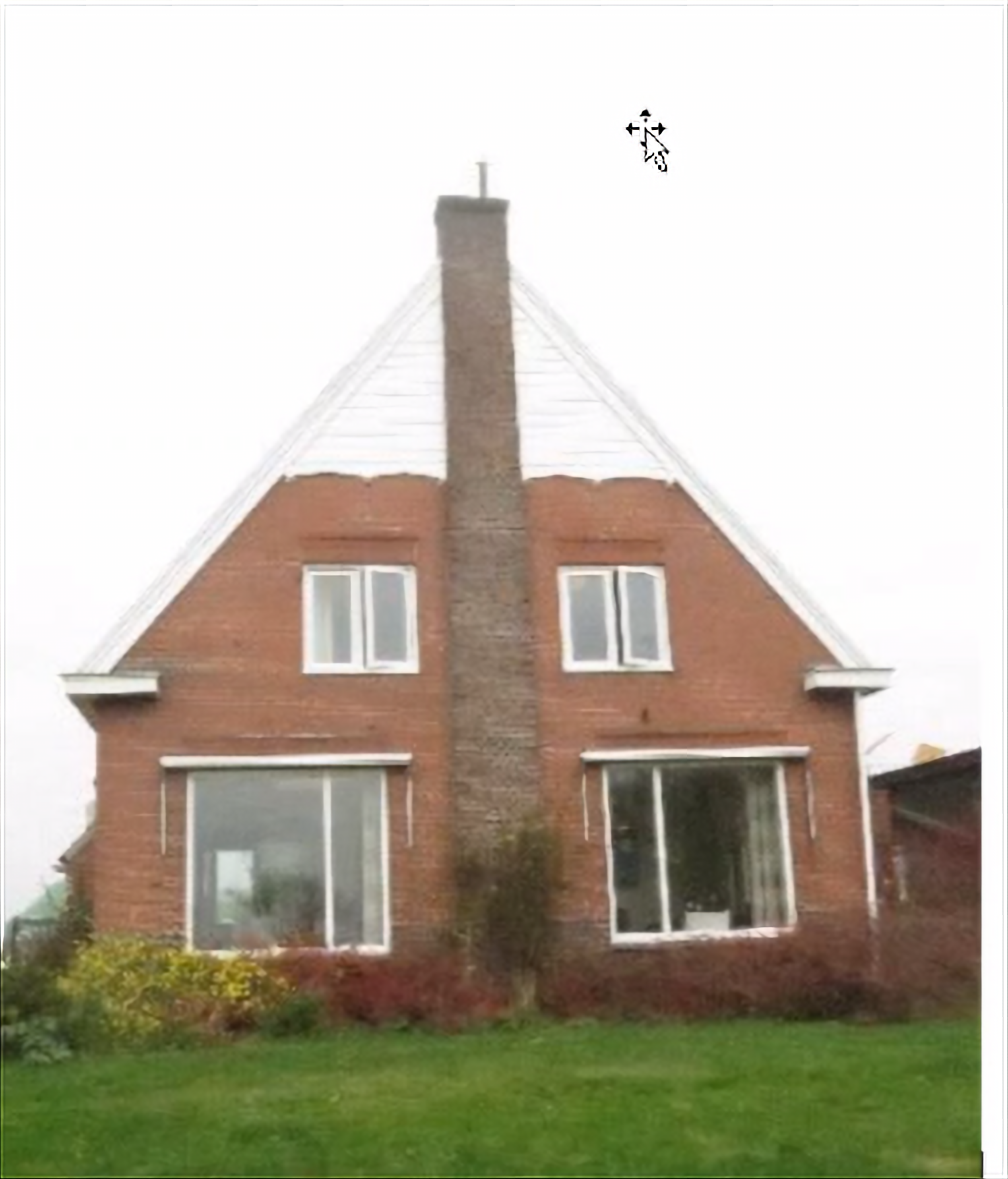
Figure 2.31 Vertical chimney duct. Should be included in the geometrical model.
2.6.10. Adjusting foundation strips
The contours of the foundation strips that are generated with the function
viia_create_foundation_walls_and_strips() are automatically
adjusted so that they do not overlap if the argument adjust_strips is set to True. Alternatively, the user can also
adjust specific foundation strips with the use of the function
viia_adjust_fstrips(). Currently, this function is limited to T-connections
(in which the upper part of the ‘T’ is continuous), perpendicular directions and corner connections with an arbitrary
angle. Other type of connections might not be available and require manual inputs. For T-connections in which the upper
part of ‘T’ is not continuous, the function may be used by inputting two fstrips at a time.
For foundation strips underneath cavity walls (, i.e., the foundation is not stepped), the foundation strips are
adjusted so that the corner points of the foundation cavity walls are also included in the adjusted contour. The figure
below shows the adjusted contour (highlighted in red) of such a case.
Note that complex connections in foundations (different details applied and connecting more than 2 walls at 1 point) are cause of issues and a lot of manual work to correct. As the foundation is modelled with linear elastic materials, the behaviour of the foundation is simplified for the cause of the analysis. In most cases the simplification is also applicable for the geometry of the foundation. If in doubt, consult your technical master.
2.6.11. Floors on sand
In many objects there are floors cast directly on the sand. These floors are often disconnected from the structure of
the building. It is advised to model those floors, to have correct values that are derived from the model (for example
in the engineering database), to have proper support for any structure on these floors, and a proper model description
in the C3 appendix. These floors should be added as additional_supported_shapes when applying boundary conditions (see
Step 8: Apply the boundary conditions and base motions for flexbase to the model and Step 9: Connections). To disconnect these floors from the structure the function
viia_disconnect_shape() is available. It applies a disconnect between any
connecting shape that is not in the excluded list. Note that this function should only be used after connecting all
shapes.
project.viia_disconnect_shape(shape=project.viia_get(collection='floors', id=1))
In this example the floor with ID 1 is disconnected from all shapes it connects to.
2.6.12. Other
More functions are available to edit geometry, but these are not further described here. Either take a look at the documentation of the Haskoning structural python package, or the Modelling part of the advanced workshop for the viiaPackage.
2.7. Step 6: Apply Non-Seismic Loads
A modeling difference between the seismic and other static calculations is in how loads are applied. In the case of seismic dynamic calculations, the resting and variable loads must be modeled as masses. In static calculations these should be applied as forces (e.g.: adding a mass for a live load instead of adding a distributed force).
Because the analyses in VIIA consist of static and seismic parts, the permanent loads and variable loads are treated differently. The permanent loads are incorporated in the mass of the shapes on which they are present (finishing layers on floors) or as line- and point-masses.
Imposed loads are added in the modelscript as loads and conversion functions are available to convert them to masses as present in the seismic situation, including factors.
2.7.1. Typical non-seismic Loads
Usually additional non-seismic load consist of the dead loads (coming from not modelled elements) and the part of the variable load that is present in a seismic situation must be added to the model as mentioned in the UPR (Basis of Design). These are combined (including load factors) in the load case called ‘Dead load’.
The main resting loads (self-weight) in the fem-model consist of two parts. One is the load on the floors and roofs and
the second part is the window frames in the window openings. The load ‘self-weight’ should than be created in DIANA in
the load case ‘dead load’. For this action the function viia_create_loads() should be
used.
project.viia_create_loads('Self weight')
2.7.2. Permanent Loads
2.7.2.1. Loads on floors and roofs
The load on the floors and roofs is added to the model with the
viia_create_surface_mass_floor() function. This function adds the load to the own
weight of the material. As a result, it is not necessary to enter it as a load and create a mass element to model the
mass. For this function, the name of floor or roof, the category of resting load and any additional load (kg/m2) must
be entered.
project.viia_create_surface_mass_floor(floor, resting_load='FinishLoad')
Load factors are applied according to current basis of design UPR (Basis of Design). The different loads that can be added with this function are listed in the Table below.
Table - Permanent Loads (called also dead/resting loads) |
|
|---|---|
Windows and frames in facades |
‘WindowLoad’ |
Finishing layers on floors |
‘FinishLoad’ |
Suspended ceilings |
‘CeilingLoad’ |
Light partition walls |
‘WallLoad’ |
Installations |
‘InstalLoad’ |
Flat roof (without gravel) |
‘FlatRoofLoad’ |
Flat roof (with gravel) |
‘FlatRoofGravelLoad’ |
Roof tiles (sloping roof) |
‘SlopeRoofLoad’ |
After executing the function, a message as observed in the figure below, appears on the screen (and in the log file):
11:02:20    "Updated name of shape from N1-VLOEREN-LIN-HBV-PLANKEN-0.02-0.070-0.200-0.610-2 to
            N1-VLOEREN-LIN-HBV-PLANKEN-0.02-0.070-0.200-0.610-DENSIT2373-2."

11:02:20    "N1-VLOEREN-LIN-HBV-PLANKEN-0.02-0.070-0.200-0.610-DENSIT2373-2 with added ['FinishLoad'] has an extra
            resting load of 1.0 kN/m2. And with category None has a variable load of 0.0 kN/m2."

11:02:20    "Increased density of N1-VLOEREN-LIN-HBV-PLANKEN-0.02-0.070-0.200-0.610-DENSIT2373-2: 2373.0 kg/m3."
Note that the load is processed in the self-weight of the floor. A new material has been created for this floor. This material can also be observed in DIANA. This new material includes the load as an increased density, which is stated in the name:
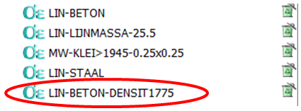
Figure 2.32 Example of the materials present in DIANA.
2.7.2.2. Loads from windows
The viia_create_mass_all_openings() function is used for the load on the window
openings. This automatically creates ‘enhanced truss elements’, above and below the window opening, with the correct own
weight. These elements are included in the static load case ‘self weight’ as well as in the dynamic analysis.
project.viia_create_mass_all_openings()
A truss element is provided at the top and bottom of all openings, without stiffness but with its own weight, in which
half of the load of the window and frame is fitted. In the current starting point report UPR (Basis of Design) this is
0.5kN/m2 (~50kg/m2). If this has to be applied to a specific wall or roof, use can be made of
viia_create_mass_wall_openings() or
viia_create_mass_roof_openings().
It may occur that openings are present in the model that are oddly shaped, or in another way not suitable for use with
the above mentioned functions. In that case the function viia_create_linemass() may be
used to add them manually.
2.7.2.3. Loads from non-modelled elements
For some elements, for example light interior walls, it may be decided to not include them in the model. They may be
omitted when they are not contributing to the seismic capacity of the building. Note that these elements can be damaged
for the in-plane load case, and should only be checked for the out-of-plane load case. Although these elements are not
explicitly modelled, their mass should be accounted for. To do this, use
viia_create_linemass(). Tip: this function can also be used in combination with the
grid system.
project.viia_create_linemass('N1', points=[grid['A6', 'L4'], grid['B6', 'L4']], value=10)
This will create a linemass on layer ‘N1’, from grid point ‘A6’ to ‘B6’ on level ‘L4’. The value of the line load is 10 kg/m.
2.7.3. Imposed Loads
For imposed loads, the function viia_create_loads() can be used:
project.viia_create_loads(load='Imposed load', category='AFloor', connecting_shapes=floor_list)
The options for imposed load categories are listed in the table below:
Table - Imposed loads (called also live loads): |
|
|---|---|
Class A - floors |
‘AFloor’ |
Class A - stairs |
‘AStairs’ |
Class A - balconies |
‘ABalc’ |
Class B - office spaces |
‘BOffice’ |
Class C - school buildings |
‘CSchool’ |
Class C - C1 to C2 |
‘C1_2’ |
Class C - C3 through C5 |
‘C3_5’ |
Class D - retail spaces |
‘DShop’ |
Class E - E1 |
‘E’ |
Class F - light vehicles |
‘F’ |
Class H - roofs (1) |
‘HRoof’ |
Note: this imposed load has a Ψ2 equal to 0 in the current Basis of Design.
2.7.4. Base motions
To perform a dynamic analysis, an acceleration signal is applied on the supports of the model. These seismic loads will not be applied in the modelscript. The seismic loads will be applied in the mainscript where the analysis requires it, see Base motions.
2.7.5. Other loads
The above loads are included in the weight of the components. There, the load ‘self-weight’ should be created in
DIANA in the load case ‘dead load’ and in case of ABAQUS a gravity load should be created in static loading step.
For this action the function viia_create_loads() is used.
The same function can be used to apply the load for the so-called ‘Rob-test’. These loads can also be removed again by
means of the function viia_remove_loads().
When it has been found necessary to apply a distributed load on a floor, This can be done with the function
viia_create_dead_loads(), for which a load has to be entered together with a list with
the areas to which it should be applied. Note that the distributed load during the dynamic calculation is not present
and therefore does not contribute to the seismic load.
The application of extra load on walls (finishing layers or façade cladding) is usually not necessary but when required
it can be done with the function viia_create_surface_mass_wall(). In this function, the
name of a wall is called and an additional load (in N/m2) is applied to that wall. This is calculated by means of the
wall’s own weight.
project.viia_create_surface_mass_wall(wall, 2000)
Note
With this function only loads are created, masses must be added separately for a seismic analysis.
2.7.6. Load combinations
The load combinations will be created in the mainscript specific for the analysis performed. These will not be part of the modelscript, see Load combinations.
2.7.7. Finalising the modelscript
In order to finalise the modelscript and prepare the model json and appendix C1, a few additional actions must be taken.
First, all shapes must be connected to each other with _viia_connect_all_shapes().
This will update all shapes in the python-memory with imprints of connecting shapes. This is required in the next
phases.
project.viia_connect_all_shapes()
It is recommended to perform this task in the model script, as the process may take some time. Then, all data
properties must be added to all shapes with viia_create_all_datas(). This will
set for example the number of integration points.
project.viia_create_all_datas()
A plot of the entire building in 3D can also be created in order to get a better overview of the whole model, and the
picture is also saved automatically in the working folder for later use. Use function
viia_create_plots(). for this.
project.viia_create_plots()
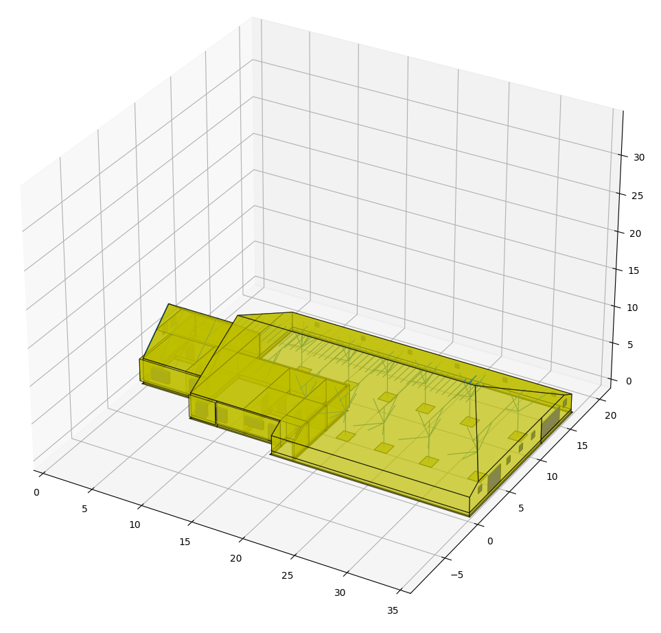
Figure 2.33 3D plot of the building in PyCharm / matplotlib.
The model json that will be used in the mainscript can now be generated with
_viia_write_dump():
project.viia_write_dump(project.name + '.json', project.workfolder_location)
Finally, the pictures for Appendix C3 must be created, as well as the appendix itself. These two actions are elaborated in Step R1 below.
2.8. Step R1: Reporting structural setup of the building
This step concerns the reporting of the object’s structural system.
Note
Before starting with this initial step of the reporting process, please carefully go trough the Overview and Instruction of the Reporting guide.
Note
This protocol describes the appendices required for the latest tender specification (‘vraagspecificatie’). Older specifications might have a different table of contents and the information required might be different.
In this phase only the appendix C3 is created for the fixed base model. In a subsequent phase the modelling of connections will be added to this appendix).
2.8.1. Appendix C3 - Description of the Finite Element Model
Appendix C3 consists of a detailed description of the finite element model. Please refer to Overview of the reporting process for elaboration on the creation of Appendix C3. More information is provided in Appendix C3.
After completing all the steps of the starting phase, the model is ready and it possible to continue working on the ‘Fixed base model phase’.