How to check for compliance SBS
This guide contains the procedures for the checks to be performed accoring to chapter 9 of the Basis of Design for SBS. In this guide the compliance checks provided in the Basis of Design are further elaborated for the assessment of modal response spectrum analysis (A5 and A17).
Masonry
Walls
In-plane behaviour
The in-plane assessment of masonry walls can be found in section 9.2.2.1 in the Basis of Design for SBS. An example for the assessment of the in-plane shear for masonry walls can be found here: Masonry in-plane shear check.
Out-of-plane behaviour
For the assessment of the out-of-plane behaviour, the L4 -sheet is used. This will be elaborated in the next chapter.
Autoclaved aerated concrete walls / Ytong
The assessment of autoclaved aerated concrete (AAC) / Ytong walls is elaborated in section 9.2.2.2 of the Basis of Design for SBS.
Nehobo floors
The assessment of Nehobo floors can be found in section 9.2.2.3 in the Basis of Design for SBS.
Concrete
Concrete walls
Concrete walls are checked for tension, compression, bending and in-plane shear. The assessment is elaborated in section 9.2.3.2 in the Basis of Design for SBS. If these checks do not pass, a cross section analysis is done.
The cross section analysis for a concrete wall is done with an Excel-tool (“(Beam) T-normaalkracht en Buiging EC2 v3.2”, which can be found in the Rekentools folder). In this excel, every text that is written in blue is input from the engineer. For concrete walls, the ‘plate’ option is used in the Excel-tool. For concrete walls, the cross section is checked for normal force and bending moment. As DIANA only gives distributed forces for shell elements, concrete walls are checked per meter length. This means that the width of the plate should always be inputted as 1000 mm in the excel. The normal force is taken as the lowest compression force (from NyyH and NyyL) in the piers of the walls from DIANA (DIANA: “STRESS TOTAL DISFOR LOCAL”). A high compression force is favourable for the behaviour of the wall, therefore the check is carried out with the lowest compression force in the piers as this is more conservative. Tension may occur in spandrels and near windows, however this is (usually) not the governing cross section to check. The bending moment is taken as the largest from MxxH and MxxL from DIANA, this is the out-of-plane bending (DIANA: “STRESS TOTAL DISMOM LOCAL”).
Example cross section calculation concrete wall: In this example, a wall with a height of 2.75 m and a thickness of 200 mm is used. It is assumed that the cross section of the wall has bottom and top reinforcement of Ø8 mm and c.t.c. 200 mm. Shear reinforcement of Ø12 mm and c.t.c. 150 mm is also present. The reinforcement is of type B500B. The compressive forces in the wall can be seen in Figure 1 10. In the piers, the normal forces vary from -10.25 kN/m to -30.87 kN/m. The smallest compression force is taken for the calculation as this leads to more conservative results, therefore the value of -10.25 kN/m is taken. The maximum bending moment around local x-axis can be seen in Figure 1 11. The maximum bending moment in the piers is 0.92 kNm/m. A local peak in bending moment is found at the top of the wall, this is not the governing bending moment as it is very local. With this information, the cross section calculation Excel can be filled in (see Figure 1 12). Everything that is marked in red in this image should be filled in by the engineer. A wall is always calculated per meter length, therefore the width in the excel is 1000 mm.
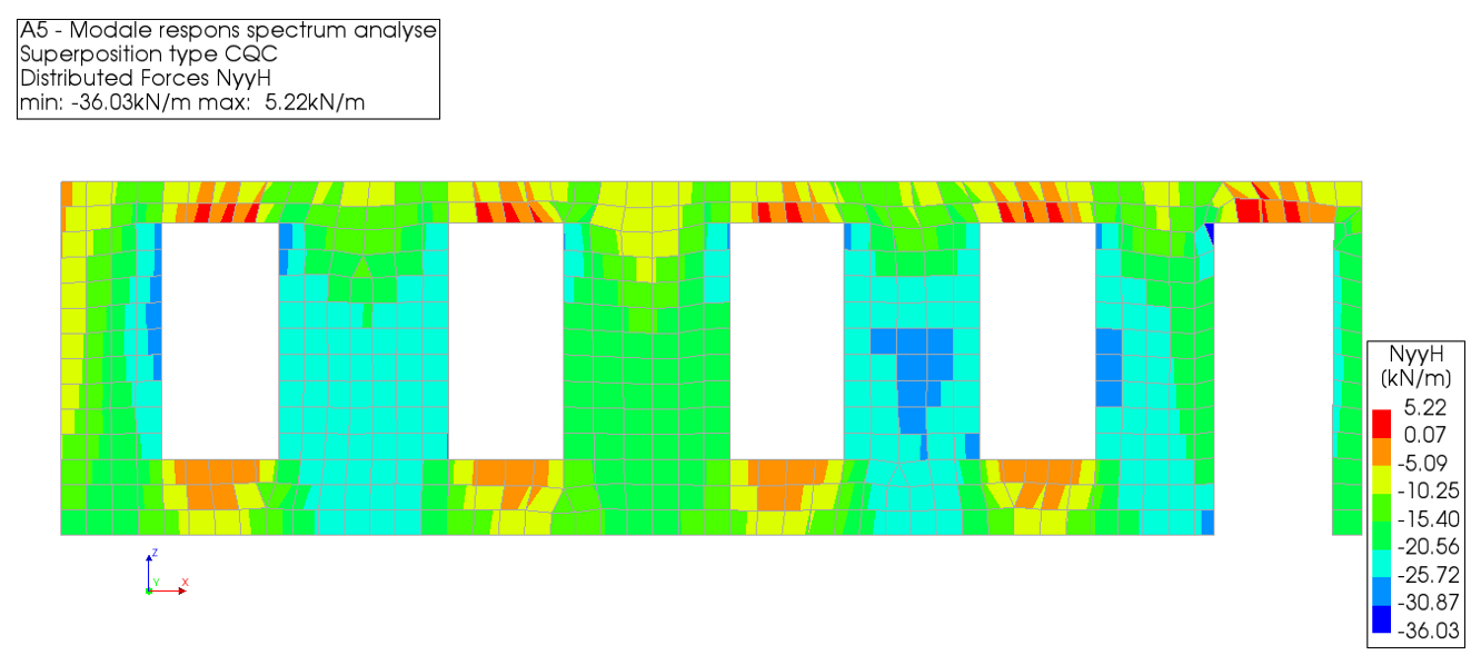
Figure 1 - Normal forces in the concrete wall.
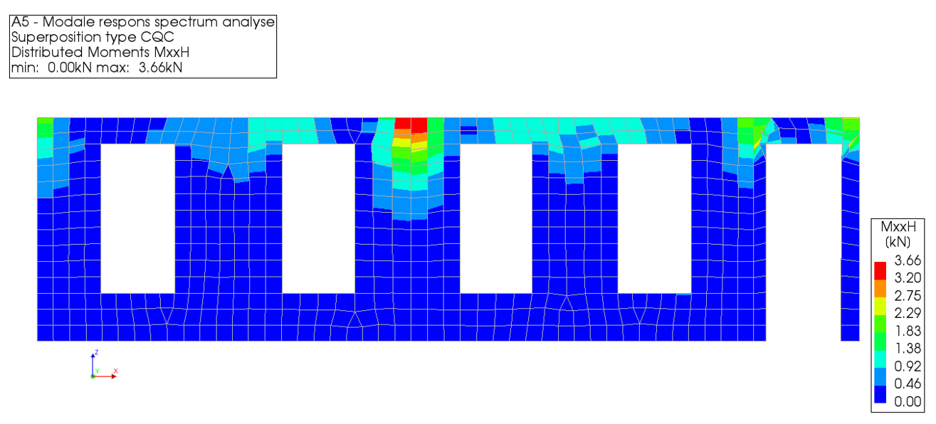
Figure 2 - Bending moment in the concrete wall.
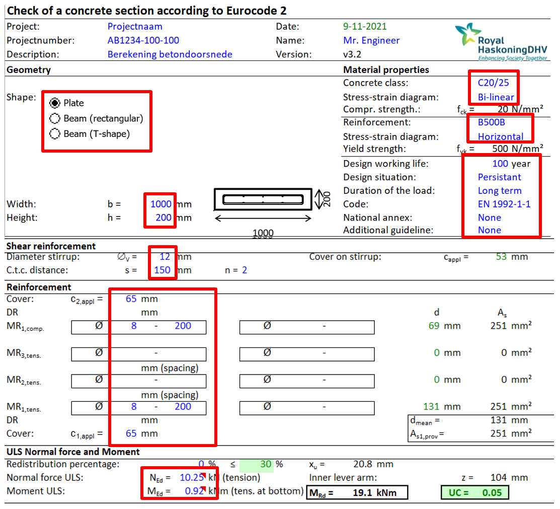
Figure 3 - Input cross section calculation Excel.
In above sheet, the engineer can input only the reinforcement at the top of the compression zone and the bottom of the tension zone (reinforcement in the most outer fibres of the cross section) as a first check. This is input in the field MR1,comp and MR1,tens. If the cross section does not pass and there is more reinforcement present in reality, more reinforcement can be inputted in the tension zone: MR2,tens and MR3,tens. The reinforcement that is present in the tension zone is reported in the Technical Retrofit Advisory report.
After inputting all the necessary information, the Unity check will be visible in the ‘UC’ cell (see Figure 1 12) after clicking on the button ‘Compute ULS’.
If reinforcement information is not present for the cross section, please refer to the Eurocode for standardised values.
If the cross section calculation concludes that the concrete wall does not pass, retrofitting measures are required.
Solid concrete floors
Concrete floors are checked for in-plane shear. The assessment is elaborated in section 9.2.3.3 in the Basis of Design for SBS. If the in-plane shear check does not pass, a cross section analysis is done.
The cross section analysis is done with an Excel-tool (“(Beam) T-normaalkracht en Buiging EC2 v3.2”, which can be found in the Rekentools folder). In this excel, every text that is written in blue is input from the engineer. For concrete floors, the ‘plate’ option is used in the Excel-tool. For concrete floors, the cross section is checked for in-plane shear. As DIANA only gives distributed forces for shell elements, concrete floors are checked per meter length. This means that the width of the plate should always be inputted as 1000 mm in the excel. The normal force is taken as the highest compression force (from NxxH, NyyH, NxxL and NyyL) in the floor from DIANA (DIANA: “STRESS TOTAL DISFOR LOCAL”).
Example cross section calculation concrete floor:
In this example, a floor with a thickness of 100 mm is considered. It is assumed that the cross section of the floor has bottom and top reinforcement of Ø8 mm and c.t.c. 200 mm. Shear reinforcement of Ø12 mm and c.t.c. 150 mm is also present. The reinforcement is of type B500B. The compressive forces in the floor can be seen in Figure 6 4. The largest compressive force is -13.93 kN/m (not including local exceedances). With this information, the cross section calculation Excel can be filled in (see Figure 1 12). Everything that is marked in red in this image should be fille in by the engineer. The normal force and shear force are taken as zero. A floor is always calculated per meter length, therefore the width in the excel is 1000 mm.
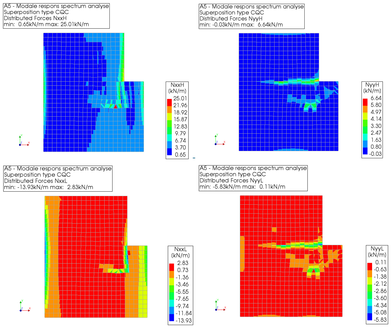
Figure 4 - Normal forces in concrete floor.
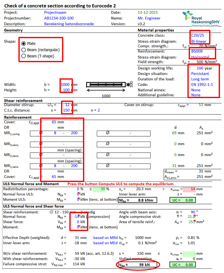
Figure 5 - Input cross section calculation Excel.
In above sheet, the engineer can input only the reinforcement at the top of the compression zone and the bottom of the tension zone (reinforcement in the most outer fibres of the cross section) as a first check. This is input in the field MR1,comp and MR1,tens. If the cross section does not pass and there is more reinforcement present in reality, more reinforcement can be inputted in the tension zone: MR2,tens and MR3,tens. The reinforcement that is present in the tension zone is reported in the Technical Retrofit Advisory report.
After inputting all the necessary information, the shear capacity of the floor per meter can be seen in the ‘VRd’ cell (see Figure 6 5) after clicking on the button ‘Compute ULS’. This capacity needs to be compared to the in-plane shearforces of the floor (NxyH and NxyL) in DIANA (DIANA: “STRESS TOTAL DISFOR LOCAL”). If the occurring in-plane shear forces exceed the capacity as calculated in above excel, retrofitting measures are required.
If reinforcement information is not present for the cross section, please refer to the Eurocode for standardised values.
Other concrete floors
The assessment of other types of concrete floors is elaborated in section 9.2.3.4 to 9.2.3.10 in the Basis of Design for SBS.
Concrete beams and concrete columns
Concrete beams and columns are checked for tension, compression and bending. The assessment is elaborated in section 9.2.3.11 in the Basis of Design for SBS. If these checks do not pass, a cross section analysis is done.
The cross section analysis is done with an Excel-tool (“(Beam) T-normaalkracht en Buiging EC2 v3.2”, which can be found in the Rekentools folder). In this excel, every text that is written in blue is input from the engineer. For concrete beams and columns, the ‘beam’ option is used in the Excel-tool. For concrete beams, the cross section is checked for bending moment. For concrete columns, the cross section is checked for normal force and bending moment. The normal force is taken as the largest of NxH and NxL from DIANA (DIANA: “STRESS TOTAL FORCE LOCAL”). The bending moment is taken as the largest from MyH, MyL, MzH and MzL from DIANA (DIANA: “STRESS TOTAL MOMENT LOCAL”).
Example cross section calculation concrete beam:
For the beam, it is determined whether bending around local y-axis or local z-axis is governing (larger bending moment). For beams, usually bending around local y-axis is governing. The bending moment is taken as the largest from MyH, MyL, MzH and MzL from DIANA.
Please note: depending on the governing bending moment, the cross section may flip 90º. The tension and compression side in the cross section affects the configuration of the reinforcement.
In this example, the beam from Figure 1 13 is used. The beam has a height of 625mm and a width of 445mm. The reinforcement is of type QR24. The maximum bending moment occurs around local y-axis and can be seen in Figure 1 14. With this information, the cross section calculation Excel is filled in (see Figure 1 15). Everything that is marked in red in this image is filled in by the engineer.
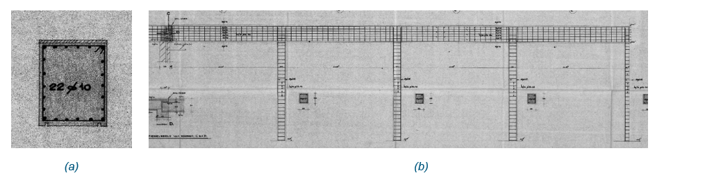
Figure 6 - Example concrete beam: (a) Cross section, (b) Shear reinforcement.
Figure 7 - Maximum occurring bending moment.
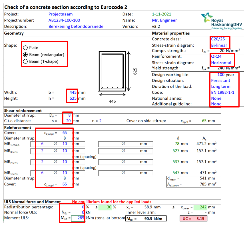
Figure 8 - Input cross section calculation Excel.
In above sheet, the normal force is set to zero for beams, as concrete beams are only checked for bending. The maximum occurring bending moment is taken from DIANA (see Figure 1 14). As a first check, the engineer inputs only the reinforcement at the top of the compression zone and the bottom of the tension zone (reinforcement in the most outer fibres of the cross section). This is input in the field MR1,comp and MR1,tens. If the cross section does not pass and there is more reinforcement present in reality, more reinforcement can be inputted in the tension zone: MR2,tens and MR3,tens. The reinforcement that is present in the tension zone is reported in the Technical Retrofit Advisory report.
After inputting all the necessary information, the Unity check will be visible in the ‘UC’ cell (see Figure 1 12) after clicking on the button ‘Compute ULS’.
If reinforcement information is not present for the cross section, please refer to the Eurocode for standardised values.
If the cross section calculation concludes that the concrete beam does not pass, retrofitting measures are required.
Example cross section calculation concrete column:
For the column, it is determined whether bending around local y-axis or local z-axis is governing (larger bending moment). The bending moment is taken as the largest from MyH, MyL, MzH and MzL from DIANA. The normal force is taken as the largest from NxH and NxL from DIANA.
Please note: depending on the governing bending moment, the cross section may flip 90º. The tension and compression side in the cross section affects the configuration of the reinforcement.
In this example, the column from Figure 1 16 is used. The column has a cross section of 330x380mm. The reinforcement is of type QR24. The maximum bending moment occurs around local z-axis and can be seen in Figure 1 17. The maximum occurring normal force can be seen in Figure 1 18. With this information, the cross section calculation Excel is filled in (see Figure 1 19). Everything that is marked in red in this image is filled in by the engineer.
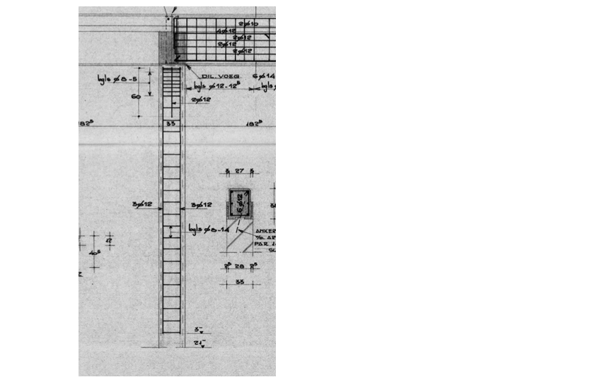
Figure 9 - Example concrete column.
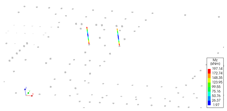
Figure 10 - Maximum occurring bending moment.
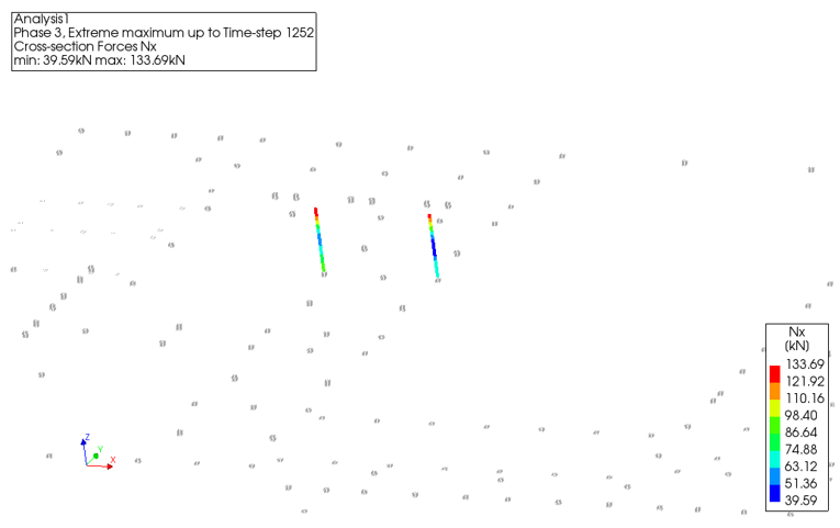
Figure 11 - Maximum occurring normal force.
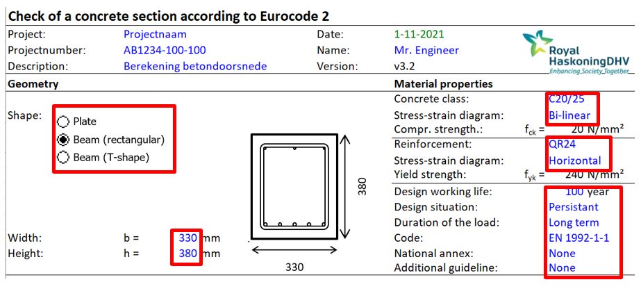
Figure 12 - Input cross section calculation Excel.
In above sheet, the normal force and bending moment is taken from DIANA (see Figure 1 17 and Figure 1 18). As a first check, the engineer inputs only the reinforcement at the top of the compression zone and the bottom of the tension zone (reinforcement in the most outer fibres of the cross section). This is input in the field MR1,comp and MR1,tens. If the cross section does not pass and there is more reinforcement present in reality, more reinforcement can be inputted in the tension zone: MR2,tens and MR3,tens. The reinforcement that is present in the tension zone is reported in the Technical Retrofit Advisory report.
After inputting all the necessary information, the Unity check will be visible in the ‘UC’ cell (see Figure 1 12) after clicking on the button ‘Compute ULS’.
If reinforcement information is not present for the cross section, please refer to the Eurocode for standardised values.
If the cross section calculation concludes that the concrete column does not pass, retrofitting measures are required.
Steel
The assessment of steel elements is elaborated in section 9.2.4 of the Basis of Design for SBS.
Timber
Solid timber beams and columns
The assessment of solid timber beams and columns is elaborated in section 9.2.5.2 of the Basis of Design for SBS.
Stud walls with wood-based panels
The assessment of stud walls with wood-based panels is elaborated in section 9.2.5.3 of the Basis of Design for SBS.
Timber floors
The assessment of timber floors is elaborated in sections 9.2.5.4 and 9.2.5.5 of the Basis of Design for SBS.