4. Phase 3 - Strengthening phase
If any structural elements do not comply with the safety criteria of the NPR 9998, they will require strengthening measures. The following steps should be taken at this stage:
Determining measures
Recalculating the strengthened situation
Reporting the advised measures
4.1. Determining measures
The GMC provides a large range of options in strengthening measures which will usually offer a suitable solution for failing elements (see GMC Webtool). They are categorized by the nature of the measure:
L1: Mitigation of direct threats
L2: Couplings/Connections
L3: Floors and roofs
L4: Walls out-of-plane
L5: Walls in-plane
L6: Foundation
L7: Demolition of elements
L8: Changing system behaviour
Typical strengthening requirements may be identified for this typology of building (low rise URM). Discuss with the senior engineer possible expected measures that can be identified even before conducting a detailed analysis. Remember in all cases the chain of vulnerability of your building, where the IP and the OOP capacities of the members or the building subsystems are recommended to be checked to be compliant before addressing the condition of floors and connections.
4.2. Frequently appearing measures
4.2.1. Strengthening existing connection between wall and floor or wall and roof
If the on friction-based capacity of an existing connection does not comply to either loads perpendicular to the wall (out of plane) or a combination of perpendicular and parallel loads, it must be strengthened.
Before deciding to strengthen an existing connection a couple of assumptions need to be taken into account:
In case of interior walls, the floor beams are always encased in the wall, which results in a very high capacity, so the connection will not fail.
At façade walls, the roof and/or floor beams are connected to wall plates, which are fastened to the walls, or the beams are held in place by wedges. In this case the capacity is high and will not fail.
These assumptions need to be taken into account always, unless there are clear pictures which disprove the assumption. In this case a measure needs to be taken, if the capacity is not high enough.
It is assumed that the existing connection can resist the force up until its capacity. The strengthened part needs to be able to take the exceeding part of the forces. This exceeding force needs to be higher than 0,10 kN/m for a measure to be necessary.
In the TVA a table should be made with the connections that need to be strengthened. The connections are identified by the connected structural elements. This table (see Table 4.1) should also show the force that the strengthening measure needs to be able to resist.
Table 4.1: Reference table with forces that strengthened connections should resist |
||||
|---|---|---|---|---|
Connection ID |
Out-of-plane |
F ⟘ [kN/m] |
Diaphragm Action |
F ∥ [kN/m] |
Floor 03-Beam02 |
✗ |
- |
✓ |
0.80 |
Floor 04-Beam01 |
✗ |
- |
✓ |
0.69 |
Floor 05-Beam02 |
✗ |
- |
✓ |
0.40 |
Floor 05-W05 |
✓ |
0.26 |
✓ |
0.33 |
4.2.2. Applying new connection between wall and floor or roof
Applying a new connection is necessary for non-loadbearing walls and walls which are regarded as NSCE’s. This connection is applied on the top and is always at least necessary for a support out-of-plane, because all walls are assumed vertically spanning in the out-of-plane assessment. Additionally, non-load bearing seismic walls require to be connected to floor diaphragms for them to be able to transfer seismic mass to perpendicular walls.
In the TVA a table should be made with the connections that need to be designed between walls and floor - or walls and roof diaphragms. This table (see Table 4.2) should also show the force that each new connection needs to be able to resist. This is equal to the total calculated out of plane force and the total diaphragm force coming from the floor or roof check (combination of multiple floor and roof diaphragms is possible and should be considered).
Table 4.2: Reference table with forces that new connections should resist |
||||
|---|---|---|---|---|
Connection ID |
Out-of-plane |
F ⟘ [kN/m] |
Diaphragm Action |
F ∥ [kN/m] |
Floor 01-WA |
✓ |
0.53 |
✓ |
1.93 |
Floor 01-WC |
✓ |
0.21 |
✓ |
2.09 |
Floor 02-WC |
✓ |
0.22 |
✓ |
1.10 |
Floor 02-WE |
✓ |
0.24 |
✓ |
1.12 |
Floor 03-W05 |
✓ |
0.31 |
✓ |
0.74 |
Floor 05-W05 |
✓ |
0.26 |
✓ |
0.33 |
Roof 01-WA |
✓ |
0.08 |
✓ |
0.21 |
Note
The required connection capacities of PSSE’s are determined in the tool. The required ones for the NSCE walls aren’t, so these need to be calculated manually, and added in a separate table.
4.2.3. Strengthening diaphragm
If either the shear or deformation capacity of a diaphragm is exceeded, then the diaphragm needs to be strengthened. Usually diaphragms comply. If they don’t comply, it is most likely due to exceedance of the shear capacity (exceedance of the deformation capacity rarely occurs).
In chapter 5 of the TVA a table should be made with the diaphragms which need strengthening. This table (see Table 4.3) should also show the force the strengthened diaphragm needs to be able to resist.
Table 4.3: Reference table with forces
that strengthened diaphragms should resist
|
|
|---|---|
Floor/Roof ID |
V d;diaphragm [kN/m] |
Floor 01 |
0.53 |
Roof 01 |
0.21 |
Strengthening of a diaphragm is also required when the present plates or planks on the floor or roof (almost always the roof only) are not able to provide proper diaphragm action. Table 4.4 shows the efficiency of floor or roof diaphragms assembled of different types of plates.
Table 4.4: Types of plates and efficiency of floor or roof diaphragms |
|
|---|---|
Plate Type |
Strengthening Required? |
Multiplex |
No, if thickness ≥ 9 mm |
OSB |
No, if thickness ≥ 9 mm |
Hard- and/or softboard |
Yes, always |
Kippengaas (Chickenwire net) |
Yes, always |
Spaanplaat (Chipboard) |
No, if thickness ≥ 12 mm |
Stramit (compressed straw encased in paper) |
Yes, always |
Gypsum board |
Yes, always |
4.2.4. Cavity Ties
Non-bearing leaves (usually the outer leaves) are not supported on top. If the wall is not allowed to fail an NLKA must be performed. In the NLKA the wall is assumed to be vertically spanning. To realize this, cavity ties need to be applied on top of the wall on the level of the first floor.
This goes for all the cases, so also when there are already cavity ties present along the whole height of the wall, because there is a high probability there will be no anchors present at the desired location to be able to provide a support at the top.
4.2.5. Connection between floor and roof
When seismic forces need to be transferred from a floor to a façade wall through a roof diaphragm, there has to be a proper connection between the floor and roof diaphragm. If this is not present then a connection needs to be applied.
4.2.6. Replacing masonry wall
Replacing masonry walls usually occurs for masonry walls which are present on the first floor or in the attic. In its place a wooden wall is placed. It could be that the wall complies when assessed with the semi-probabilistic method. However, it requires a connection on top of the wall. Discuss with the cost engineer in this case, which option is economically more feasible, applying a connection or replacing the entire wall. Surprisingly in some cases the latter option can be cheaper.
4.2.7. Replacing masonry chimney
If a masonry chimney fails, then it should be replaced. Replacement usually happens by using a lightweight material. In the TVA it should be mentioned if replacing of a masonry chimney is required.
4.2.8. Replacing sloped chimney shaft (part in attic)
If a sloped chimney shaft of masonry is present in the attic area, it should be replaced by a lightweight shaft. It should be mentioned in the TVA if the replacement is necessary.
4.3. Out-of-plane measures
Out of plane measures can be determined by using the L4-excelsheet [5].
Before applying an out-of-plane measure one needs to apply a couple of extra checks to see if it possible to make the wall comply:
Decrease the height of the wall. Can be applied for outer leaves, which are usually higher than inner leaves. It is justified because cavity ties will be applied at level of first floor, so then a support is created.
Assume that a small vertical load is present of either 0,1 kN/m, or 0,5m*resting_load. This might help if a wall is not complying by a little bit (UC = 1.01-1.05)
Take into account that the wall can be two-way spanning, which is beneficial for the out-of-plane capacity. By using the L4-excelsheet [5] this new capacity can be checked. It is usually beneficial for walls with length 1.5 – 3.0 m. Longer than this and the effect decreases. For cavity walls there is also an additional check portrayed in the flowchart in Figure 4.1.
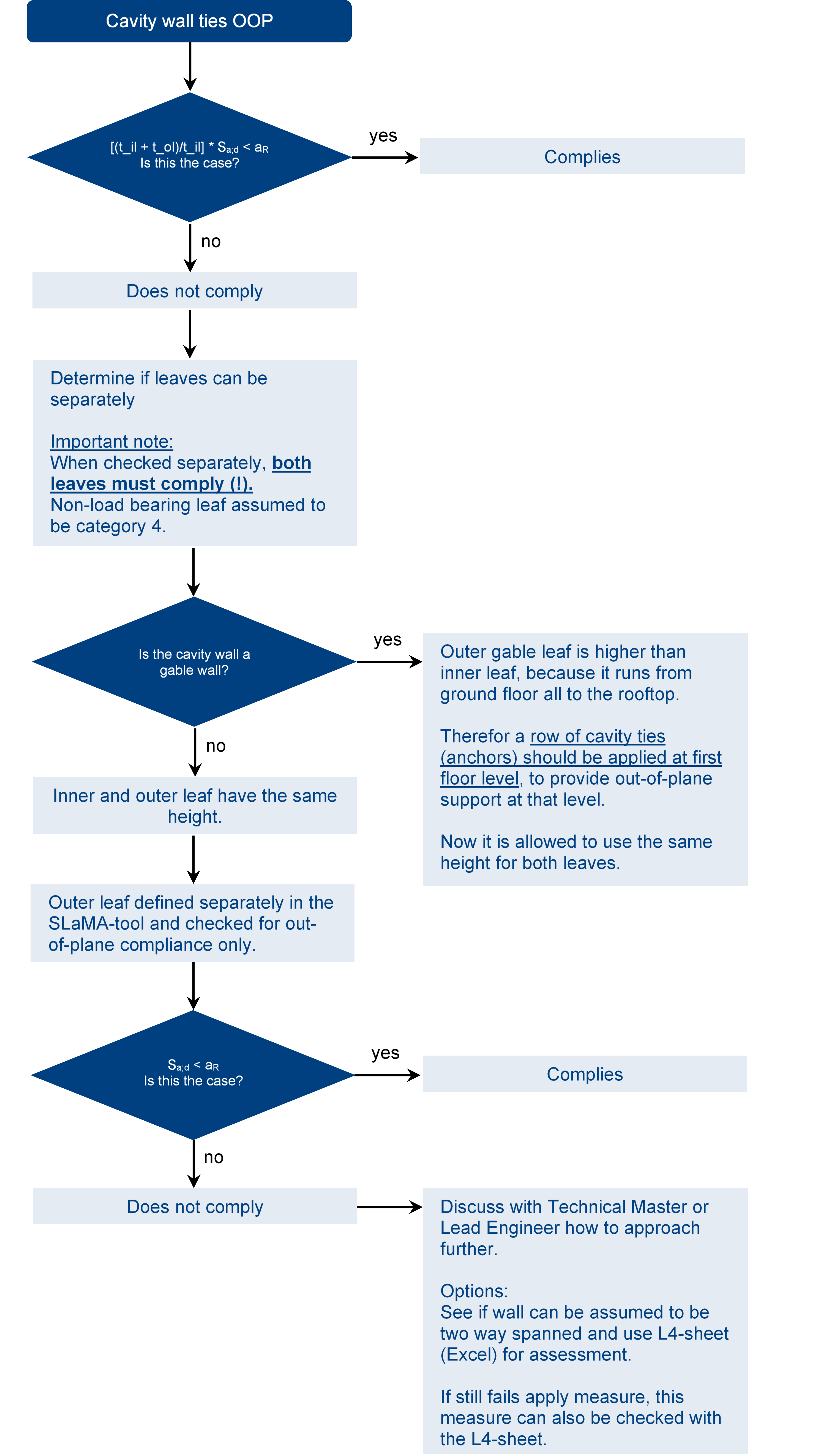
Figure 4.23 Flowchart cavity wall ties OOP
4.4. In-plane measures
Before applying an in-plane measure one needs to apply a couple of extra checks to see if it possible to make the wall comply:
Check if the wall can be an NSCE, so that an in-plane check is not required anymore. In this case the analysis should be done once more;
Check if the amount of seismic mass can be reduced, by redistributing it;
Check if the opening can be redefined, usually a larger spandrel can have a lot of positive influence;
Check both earthquake directions separately, so that the pier heights are taken less conservatively
Note
When checking both directions separately, this method can be sensitive to a change in the failure mechanism (from shear to rocking and vice versa). So the evaluation should be done with caution.
If after these checks the wall does not comply, then a strengthening measure needs to be applied.
A couple of options:
Closing an opening: this is something that the owner/client would not often want, but it is possible to discuss it during the measures meeting (maatregelenoverleg). Also important to pay attention to where the opening is. If it is a small opening in a storage, bathroom or toilet it might be alright, however not for large openings in a living room or kitchen.
Enlarging opening: this could cause a shift in the failure mechanism, most likely to rocking, which could result in extra deformation capacity.
Applying concrete jacketing of 20 mm (spray concrete with carbon fibre mesh)