How to standardise the unknown information from inspection
The information provided by the desk study and inspection may be incomplete, unclear or missing. In this chapter the standardisation starting points are presented, which help to consider the most realistic case per structural element; foundations, floors, roofs, walls and connections. Use the following guidelines in consultation with the lead engineer.
Foundations
Typology of
the building
or building
part
|
Foundation width size per wall material and type |
Footing columns |
||||||||
|---|---|---|---|---|---|---|---|---|---|---|
External masonry wall
(CS or CMt)
|
Internal masonry wall
(CS or CMt)
|
Light weight internal
“load bearing”
|
Timber
& Masonry
|
Concrete
& Steel
|
||||||
Single
layer
|
Cavity
wall
|
Single
layer
|
Cavity
wall
|
Single layer
over slab on
sand
|
Timber |
Steel |
Other |
|||
1 story
per 1950’s
|
tw* + 400
“masonry
stepped”
w
|
– |
tw + 400
“masonry
stepped”
|
– |
tw + 2ts**
(plain
concrete)
|
300 |
– |
– |
500x500 |
– |
2 stories
per 1950’s
|
3tw or tw*
+ 400
“masonry
stepped”
w
|
– |
3tw or tw*
+ 400
“masonry
stepped”
|
– |
– |
– |
– |
– |
800x800 |
– |
1 story
post 1950’s
(concrete
foundation)
|
tw + 300 |
500 |
tw + 300 |
500 |
tw + 2ts
(plain
concrete),
tw + 5ts
(reinforced
concrete) or
tw + 10ts
(precast
concrete)
|
300 |
400 |
400 |
500x500 |
700x700 |
2 stories
per 1950’s
(concrete
foundation)
|
– |
600 |
tw + 500 |
600 |
– |
– |
– |
– |
800x800 |
1000x1000 |
Notes
The units of this table are in mm.
This table is for 1 and 2 stories building including attics and for houses located in the Groningen region in case drawings
or inspection info is not available.
t: CS & CM are Calcium Silicate and Clay Masonry brick walls.
w: just for hard clay layer / “vlijlaag” or also for post-1950’s stepped foundation on “stampbeton” and/or soil improvements.
tw: in mm is the thickness of the wall either for a since layer wall or the sum of the two layers and the cavity for cavity walls.
ts: in mm and is the thickness of the ground level slab floors.
|
||||||||||
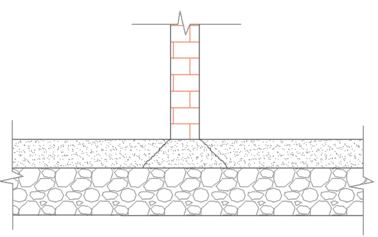
Figure 7 Internal masonry wall over a plain concrete slab.
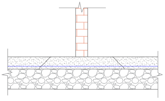
Figure 8 Internal masonry wall over a reinforced concrete slab.
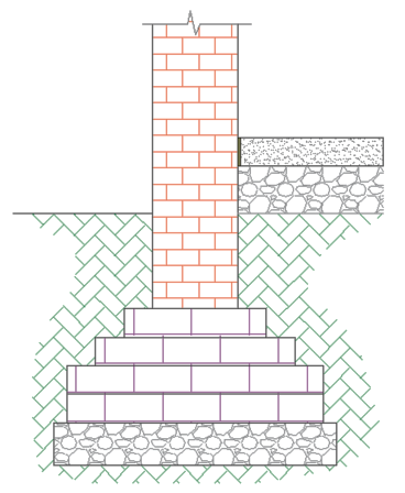
Figure 9 Masonry stepped foundation.
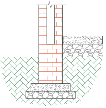
Figure 10 Cavity wall foundation.
Floors
Unknown |
Standardisation |
|
|---|---|---|
General |
Floor material
|
Check the pictures to get an idea about the used
material. Check if the floors above and below are similar.
If yes, use the same properties.
If no, find similar floors from other objects.
|
Presence of finishing
layers
|
Assume there are no finishing layers.
|
|
Ground floor on sand
|
Do not model the floor.
|
|
Timber |
Floor board
|
By looking at the pictures it is usually clear what
material is used. If this is not possible, assume the
material based on the construction/renovation date;
before 1970 planks and after 1970 plates.
|
Floor board thickness
|
Planks: thickness 18 mm and width 165 mm
Plates: one layer, 12 mm
|
|
Floor joist direction
|
Check the pictures to see If the beams or planks are
visible and assume accordingly. If this is not possible,
assume the shortest distance.
|
|
Floor joist dimensions
|
Center to center distance: 600 mm
Height: 1/20 of the floor joist length
Width: 1/3 of the floor joist height
|
|
Concrete |
Material
|
There are two main materials that can be used: in-situ and
hollow core. By looking the floor from below it is apparent
which material is used. If there are joints along the slab,
then hollow core is used. If this is not possible,
use in-situ.
Attention: The joints can be covered so they cannot be seen.
|
In-situ concrete
thickness
|
Shortest floor span/25
|
|
Hollow core concrete
thickness
|
Shortest floor span/30 and then decide which characteristic
thickness is closer; 150, 200, 260, 320 or 400 mm.
Assume thickness of compression layer equal to 50 mm.
|
|
Roofs
Unknown |
Standardisation |
|
|---|---|---|
Timber |
Presence of timber
beams
|
From the pictures, gather the missing timber beams.
However, judge which of them are important for the
structure. Avoid modelling every detail.
|
Support on cavity
walls
|
Usually, the roof supports on the inner cavity wall.
|
|
Roof board
|
By looking at the pictures it is usually clear what
material is used. If this is not possible, assume the
material based on the construction/renovation date;
before 1970 planks and after 1970 plates.
|
|
Connection between
timber roof and
timber attic floor
|
A beam should be modelled at the intersection of the
plane of the roof and the plane of the attic. This beam
should have a hinge connection with the adjacent shapes.
|
|
Connection between
timber wall plate
and masonry wall
|
Rigid connection
|
|
Connection between
timber roof rafters
and timber wall plate
|
Hinge connection
|
|
Hardboard
and / or
Softboard
|
Presence
|
Disregard this material as it is not certain if it
can provide proper diaphragm action. Consider it as an
added mass to the attaching load bearing elements,
e.g. rafters, purlins, etc.
|
Walls
Unknown |
Standardisation |
|
|---|---|---|
Masonry |
Material
|
Assume the material properties based on the renovation
stages.
|
Thickness
|
Assume the wall thickness based on the attaching walls.
|
|
Connection
|
If it is not possible to see from the pictures the wall
connection assume that it is connected.
|
|
Cavity wall ties
|
Basis of Design document (UPR) contains specific
guidelines.
|
|
Presence of
lintels
|
Apply lintels to all openings if no information is
provided.
|
|
Lintel properties
|
Material: Linear concrete
Width: Width of the attaching wall
Height: 100 mm
Supporting length: 100 mm
|
|
Connections
Unknown |
Standardisation |
|---|---|
Connection between 1D elements
(e.g. beam to beam, beam to column, etc.)
|
Hinge connection
|