How to DCF settings
The dcf-file generated for the model requires checking by the structural engineer. The analysis can be generated with
_viia_analysis(). This function generates a default dc-file for VIIA. In this
how-to guide it is explained what all the commands are and what commands VIIA requires. It states which items should
be checked before running the analysis. Where there are options that are allowed to change (refer to the Basis of
Design), an example is provided.
This document is written for the NLTH process. The differences with the NLPO are collected in the section on NLPO.
Threads for element loops
Before any other diana module is invoked (this is before any call of *) the number of threads for the element loops should be specified. The number of threads for solving the element loops should be the same as those for solving the stiffness matrix (MAXTHR), for VIIA this is by default 4. This should be done with the next command:
NUMTHR 4
Note
ONLY APPLY FOR COMMANDBOX:
NUMTHR can only be specified when running an analysis with the command box. When running directly in DianaIE it’s not possible to specify NUMTHR.
Initialisation
The following items need to be performed before the analysis can be performed.
*FILOS
INITIA
*INPUT
*FORTRAN
USE "E:\VIIA\usrifc.dll"
Note
CHECK BEFORE ANALYSIS:
Check the above mentioned commands, they need to be added if you want to run in DIANA command box.
Check if the dll-file is provided on the mentioned location.
FILOS
The central database during the analysis in DIANA is handled by FILOS, the FILe Organisation System, that is called the
FILOS-file (ff). The FILOS-file is used through the complete analysis for the final element model. The FILOS-file is
a binairy file format and cannot be moved to another computer, printed or viewed in a text editor. Most important
command is the initialisation of the file.
You can use another FILOS-file by removing the complete FILOS block from the file and to add the .ff in the command box when you initiate a new analysis. This can be useful if you want to perform an additional analysis after a first one (for example an eigenfrequency analysis).
INITIA
Opens a new FILOS-file.
RESTOR
With restore another FILOS-file can be read. This command can be used when the calculation needs to be continued with
the last step (Syntax: RESTOR FILE=file.ff). See section Bugfixing in DIANA for DCF for more information.
INPUT
When nothing is defined in this command block, the input in the dat-file will be read. Specific files can be added in
the dcf-file.
READ FILE=”model.dat (not by default in VIIA)”
Separate files with tables for ‘MATERI’ or ‘GEOMET’ can be read and redefine the previously read tables, or add these
tables in case they were not present yet.
REMAKE FILE=”test” (not by default in VIIA)
With this command the dat-file is written, especially useful when multiple dat-files are combined. It makes it possible
to check whether the correct tables are applied in the model.
FORTRAN
USE “E:VIIAusrifc.dll”
The compiled library file needs to be provided. For windows OS this is an dll-file. The location must be provided. The
dll-file is provided on all DIANA servers in E:VIIA. This command is only required when a shallow foundation interface
is applied.
First phase - apply self weight
After the initialisation the self weight and the imposed loads that are present in the seismic situation are activated. The order of application of loads is important, when applying non-linear material models. Therefore the fem-model is setup in multiple phases.
First phase block
The first phase activates the foundation element-sets are applied.
*PHASE LABEL="Activate foundation"
  BEGIN ACTIVE
    ELEMEN 'Element sets active in this phase' /
    REINFO 'Reinforcement sets active in this phase' /
    SUPPOR 'Support sets active in this phase' /
    TYINGS 'Tying sets active in this phase' /
    BEGIN AUTODE
      INTERF OFF
      BOUNDA OFF
    END AUTODE
  END ACTIVE
PHASE LABEL=”Activate foundation”
The phased analysis is initialised and a name is set for the phase.
BEGIN / END ACTIVE
This block defines the items that are present in this phase in the fem-model. When nothing is set, it is expected that
all the items are active.
ELEMEN / REINFO / SUPPOR / TYINGS
These commands provide the respective sets with elements that are active in this phase. If no sets are present use
the command NONE.
First analysis block
The next part in the dcf-file provides the analysis of the weight of the current phase. This analysis is ‘structural nonlinear’.
*NONLIN LABEL="Structural nonlinear 1"
*NONLIN LABEL=”Structural nonlinear 1”
The module structural nonlinear is started to perform a non-linear analysis on the current state of the model.
Evaluate model
Default settings for VIIA:
BEGIN MODEL
  BEGIN EVALUA
    CHECK OFF
    AVERAG ANGLE 0.349066
  END EVALUA
END MODEL
BEGIN / END MODEL
Specifies the evaluation settings of the model for the analysis.
BEGIN / END EVALUA
Specifies the evaluation settings of the elements.
CHECK OFF
The extended test is not applied.
AVERAG ANGLE 0.349066
Average nodal normals is applied with a tolerance angle of 20 degrees (0.349055 rad).
Nonlinear effects
Default settings for VIIA:
>>>  BEGIN TYPE
       PHYSIC
       GEOMET
       BEGIN TRANSI
         METHOD NEWMAR
         BEGIN DYNAMI
           MASS
           BEGIN DAMPIN
             CONSIS
             RAYLEI OFF
           END DAMPIN
           RELBAC OFF
         END DYNAMI
         TIMEDE OFF
       END TRANSI
     END TYPE
BEGIN / END TYPE
Specifies the type of analysis.
PHYSIC
When applying this command the non-linear properties in the dat-file are used. If not specified further, all the
non-linear properties in the dat-file are applied.
GEOMET
When applying this command the geometrical non-linearity is taken into account defined by Lagrange formula.
BEGIN / END TRANSI
This command sets the transient non-linear analysis.
METHOD NEWMAR
The Newark integration scheme is used for the dynamic transient analysis. Parameter beta is 0.25 and gamma is 0.5.
BEGIN / END DYNAMI
This command defines the dynamic analysis. A consistent mass matrix is used in the. The lumped mass matrix is not used
because of the mesh refinement that is applied, which could lead to errors in the analysis. Consistent mass matrix
is the default DIANA setting.
MASS
Command to setup the mass matrix. Parameters are consistent mass matrix, including rotational terms and no distributed
loads to dynamic mass.
BEGIN / END DAMPIN
Command to setup the damping matrix.
CONSIS
The consistent damping matrix is used.
RAYLEI OFF
The Rayleigh damping is applied based on the initial stiffness matrix and is not recalculated each timestep. This is
acceptable if the plasticity in the model is limited, see for more information note VIIA_QE_R376_N041. The Rayleigh
damping values should be provided in the material definitions.
DAMPIN RAYLEI ON (Not applied in VIIA)
The Rayleigh damping is calculated based on the actual stiffness matrix. Each timestep the dampings matrix is
re-calculated. This option increases the calculation time. The Rayleigh damping values should be provided in the
material definitions.
RELBAC ON (Not applied in VIIA)
This command specifies the dynamic response caused by the base accelerations defined in the relative to base coordinate
system. This does not provide good results in combination with the Hilber-Hughes-Taylor (HHT) integration-scheme. The
Rayleigh damping is determined in another way, which seems not to be correct. DIANA-FEA is looking into this issue,
for now it is advised not to apply this option.
TIMEDE OFF
This command is not used in the analyses of VIIA. No time derivative effects.
Execute block - Start
Default settings for VIIA:
>>>  BEGIN EXECUT
       TEXT "Execute block B"
       BEGIN START
         BEGIN LOAD
           PREVIO OFF
           ADD LOADNR 1
         END LOAD
         INITIA STRESS OFF
         BEGIN EXPLIC
           SIZES 0.5 0.5
           ARCLEN OFF
         END EXPLIC
       END START
Note
CHECK BEFORE ANALYSIS:
Check if the load number references the load-combination for the dead load.
BEGIN / END EXECUT / TEXT “Execute block B”
This command block performs the load or time-steps. The dcf-file and the analysis block can contain multiple execute
blocks.
BEGIN / END START
The START command initialises the initial state of the model. The state before executing the
first load or timestep.
BEGIN / END LOAD
Defines the initial external loads.
PREVIO OFF
No initial external loads are applied.
ADD LOADNR 0
This command is used to define the applied external load. The load-combination of the dead load should be applied here.
INITIA STRESS OFF
This command defines that the stresses are not automatically calculated linear elastic at the start of the
execute block.
BEGIN / END EXPLIC
Defines explicit steps.
SIZES 0.5 0.5
This command defines the explicit steps that are used to apply the load. In the VIIA buildings, 2 steps should be
sufficient. If problems with convergence are experienced, the step-size can be decreased (and multiple steps applied).
ARCLEN OFF Arc length control is not used by default in VIIA.
Execute block - Physical nonlinear options
Default settings for VIIA:
>>> BEGIN PHYSIC
      CLEAR
      SUPPRE OFF
      DRAINE OFF
      LIQUEF OFF
    END PHYSIC
BEGIN / END PHYSIC
Defines to overrule certain physical phenomena.
CLEAR
Command to clear the displacement and rotation field at the start of this analysis.
SUPPRE OFF
Command to suppress superposition, not applied in VIIA.
DRAINE OFF
Command to for drained behaviour (of soil), not applied in VIIA.
LIQUEF OFF
Command to applu liquefaction, not applied in VIIA.
Execute block - Iteration method
The following part contains the iteration method settings and the convergence criteria. For VIIA the maximum tolerance is increased, so the analysis can continue longer so that it might find equilibrium.
>>> BEGIN ITERAT
      MAXITE 10
      METHOD NEWTON
      LINESE
      BEGIN CONVER
        BEGIN FORCE
          TOLCON 1.00000E-02
          TOLABT 1.00000E+17
          CONTIN
        END FORCE
      END CONVER
    END ITERAT
BEGIN/END ITERAT
This command block defines the iteration process to find equilibrium for the applied load or timestep.
MAXITE 10
The maximum number of iterations is depending on the iteration method. The following default values are suggested for
the VIIA project.
Regular Newton Raphson |
10 |
Secant |
20 |
Linear stiffness |
20 |
METHOD NEWTON
Specifies the applied iteration method. The Regular Newton-Raphson iteration method is applied by default in the VIIA
project. But based in the convergence behaviour another iteration method can be used. This should be mentioned in the
report, when reporting the analysis statistics.
In the Regular Newton-Raphson method the stiffness matrix is evaluated in each iteration. The prediction for the next iteration is based on the last iteration, also when there was no equilibrium found that iteration. In general little number of iterations are required, but they relatively cost more analysis time. The method gives good convergence when the prediction is close to the final result. When this is not the vase, this method leads to divergence faster.
After divergence it is possible to restart the calculation with a different iteration method applied. The Linear Stiffness or Constant Stiffness method can be selected. These methods in general require more iterations, but the time per iteration is less, because the stiffness matrix is not recalculated every iteration. Pay attention to allow for more iterations.
LINESE
The line search algorithm scales the incremental displacements in the iteration process. A more stable convergence
behaviour and faster iteration process can be found.
BEGIN/END CONVER
In this command block the convergence criteria are specified.
SIMULT
Command to apply multiple convergence criteria, both need to be satisfied. Currently this option is not used in VIIA.
BEGIN/END FORCE
For the analysis parts that apply the self weight to the fem-model the default convergence criteria is set to be based
on forces.
TOLCON 1.00000E-02
The convergence criterium for analysis parts that apply the self weight to the FEM-model is set to 0.01, refer to
note VIIA_QE_R376_N021. 1.0E-4 is the default setting in DIANA.
TOLABT 1E+17
When this value is exceeded, the analysis is considered diverged. For VIIA we use a higher value than the default
setting in DIANA.
CONTIN
This command can be applied on two locations in the dcf-file.
Used as ‘CONTIN’ inside convergence loop, which is applied in VIIA: Analysis continues even if the convergence criteria are not satisfied when the maximum set iterations is reached. Each non-converging steps needs to be checked and listed in the final report. It must be assessed that the results of this step can be trusted. Multiple non-converge steps at a row is not allowed.
Used as ‘CONTIN ON’ at the beginning of iteration definition, which is NOT applied in VIIA: When a deformation process is relatively continuous, the previous displacement can be used to predict the next step, by ratio of the load increment. In non-continuous processes this leads to bad predictions. In the VIIA project this option is thus not used.
BEGIN/END DISPLA
This sets the convergence criteria based on displacements. This is currently not applied in VIIA.
BEGIN/END ENERGY
This sets the convergence criteria based on the energy criterium. The transient part is set to use this option, see the
specific section for the transient part of this guide.
Execute block - Logging information
Default settings of DIANA are used.
Solver settings
Default settings for VIIA:
>>>    BEGIN SOLVE
         BEGIN PARDIS
           MAXTHR 4
           SUBSTR OFF
         END PARDIS
       END SOLVE
MAXTHR 4
The analysis is performed simultaneously on maximum of 4 threads. This setting has proven to be the most efficient
value in the VIIA project on the VIIA servers. When this is not specified, the maximum available threads are used.
Pay attention on the servers! When there are less threads available the analysis will delay.
SUBSTR OFF
In VIIA substructuring is not applied.
Output settings
See section on output for the structural assessment, see Output for the structural assessment. Or see section on output for the geotechnical assessment, see Output for the geotechnical assessment.
Next phases for self weight
This process is repeated for the next phase in which a part of the building is added to the fem-model.
*PHASE LABEL="Activate building layer N0"
  BEGIN ACTIVE
    ELEMEN Elementensets active in this phase
    REINFO Reinforcementsets active in this phase
    SUPPOR Supportsets active in this phase
    TYINGS Tyingsets active in this phase
    BEGIN AUTODE
      INTERF OFF
      BOUNDA OFF
    END AUTODE
  END ACTIVE
The analysis block is setup in a similar way.
*NONLIN LABEL="Structural nonlinear 1"
  BEGIN MODEL
    BEGIN EVALUA
      CHECK OFF
      AVERAG ANGLE 0.349066
    END EVALUA
  END MODEL
  BEGIN TYPE
    PHYSIC
    GEOMET
    BEGIN TRANSI
      METHOD NEWMAR
      BEGIN DYNAMI
        MASS
        BEGIN DAMPIN
          CONSIS
          RAYLEI OFF
        END DAMPIN
        RELBAC OFF
      END DYNAMI
      TIMEDE OFF
    END TRANSI
  END TYPE
  BEGIN EXECUT
    TEXT "Execute block B"
    BEGIN START
      LOAD ADD OFF
      INITIA STRESS OFF
      BEGIN EXPLIC
        SIZES 0.5 0.5
        ARCLEN OFF
      END EXPLIC
    END START
    BEGIN PHYSIC
      CLEAR
      SUPPRE OFF
      DRAINE OFF
      LIQUEF OFF
    END PHYSIC
  BEGIN ITERAT
    METHOD NEWTON
    LINESE
    BEGIN CONVER
      BEGIN FORCE
        TOLCON 1.00000E-02
        TOLABT 1.00000E+17
        CONTIN
      END FORCE
      DISPLA OFF
      ENERGY OFF
      RESIDU OFF
    END CONVER
  END ITERAT
END EXECUT
BEGIN SOLVE
  BEGIN PARDIS
    MAXTHR 4
    SUBSTR OFF
  END PARDIS
END SOLVE
This process is repeated until the fem-model is completely setup.
Seismic analysis
In the last analysis block of the last phase, two execute blocks are required create the transient analysis.
BEGIN EXECUT
  TEXT "Execute block E"
  BEGIN START
    LOAD ADD OFF
    INITIA STRESS OFF
    STEPS EXPLIC SIZES 1.0
  END START
  > Physic and iteration procedure as previous
END EXECUT
BEGIN EXECUT
  TEXT "Execute block F"
  TIME STEPS EXPLIC SIZES 0.01(1050)
  BEGIN PHYSIC
    CLEAR
    SUPPRE OFF
    DRAINE OFF
    LIQUEF OFF
  END PHYSIC
  BEGIN ITERAT
    MAXITE 10
    METHOD NEWTON
    LINESE
    BEGIN CONVER
      FORCE OFF
      DISPLA OFF
      BEGIN ENERGY
        TOLCON 1.00000E-04
        TOLABT 1.00000E+17
        CONTIN
      END ENERGY
    END CONVER
  END ITERAT
END EXECUT
BEGIN SOLVE
  BEGIN PARDIS
    MAXTHR 4
    SUBSTR OFF
  END PARDIS
END SOLVE
> Output
*END
Note
CHECK BEFORE ANALYSIS:
Check if the signal length is equal to the signal and post-seismic part.
Only commands that were not present in the self-weight steps are described:
STEPS EXPLIC SIZES 0.01(1000)
In VIIA the step-size is default set to 0.01s. Check the length of the signal to determine the number of steps, and
include some steps to calculate the post-seimic values.
SAVE 10-1000(10) (Not applied in VIIA by default)
This command saves every 10 time-steps the filos-file. When divergence occurs, the analysis can be restarted. It is
advised to apply the following commands in a batch file, to reduce the disk size demand.
@echo off
:begin
IF EXIST diana20.ff del /F diana10.ff
IF EXIST diana30.ff del /F diana20.ff
IF EXIST diana40.ff del /F diana30.ff
etc.
goto begin
END
End statement of the dcf-file.
Output for the structural assessment
When creating the dcf-file you need to know upfront which output items you required for the assessment of the building. For the VIIA project, we have derived a default dcf-file. This is based on all previous and finalised buildings, as well as on the client demands. The amount of requested output items is on the other hand slowing the calculation. The suggested default dcf-file balances these aspects.
The following result items in the analysis are set by default and in this section the use and reason for these output items are discussed. Next to it, there is also a warning what to check before running the calculation.
Displacements and relative displacements of the building elements.
Accelerations of reference points.
Cracking of masonry (crack width), including status parameters. As well as for non-linear modelled concrete.
Forces in the linear connections (and l2-measures).
Residual forces (mainly for bug-fixing).
Section forces (shear forces) of elements that are modelled with linear elastic material models.
Relative displacements of non-linear connections.
Strains of non-linear reinforcement steel.
The following table contains the description of the commands in the output-blocks. The specific output items are discussed in detail in the following sections.
DCF-COMMAND |
Description what is does in DIANA and how VIIA uses it |
|---|---|
BEGIN OUTPUT |
Start of single output block item. |
TEXT |
Name of the output. |
BINARY |
Export type DIANA native (dnb-file). |
TABULATED |
Export type tabulated file (tb-file). |
LAYOUT LINPAG 0 |
Selections for lay-out of tabulated file, syntax example for layout without page numbers (to facilitate reading tb-files in scripts). |
FILE |
Name of the output file. |
SELECT STEPS |
Select the steps for the output. LAST = last step, MAX = maximum value of all previous steps, MIN = maximum value of all previous steps. Example string: 1-10 11-1050(50) means output is requested for all steps from 1 to 11 and step 12, 62 etc. until 1050 is reached. |
SELECT ELEMEN |
Select the elements for the output (element output only). |
SELECT NODES |
Select the nodes for the output (nodal output only). |
END OUTPUT |
End of output block |
The dcf commands can be checked in the DIANA GUI:
In VIIA analysis the following output blocks are generated:
Static analysis |
|
|---|---|
OUTPUT_STATIC-NL |
Nodal/element results for the entire building (DIANA native). |
Nonlinear dynamic analysis |
|
|---|---|
OUTPUT_1A_MAX |
Maximum nodal/element results for the entire building (DIANA native). |
OUTPUT_1B_MIN |
Minimum nodal/element results for the entire building (DIANA native). |
OUTPUT_1C |
More steps during intens part of signal, maximum and minimum nodal/element results for the entire building (DIANA native). |
OUTPUT_2 |
Displacement results for reference nodes of the walls (tabulated). |
OUTPUT_3 |
Nodes to plot acceleration graph (tabulated). |
OUTPUT_4 |
Minimum and maximum stress results for linear structural elements (DIANA native). |
OUTPUT_4A |
Minimum and maximum stress results for linear structural elements (tabulated), for making plot from python. |
OUTPUT_4B |
Stress results for linear structural interfaces (tabulated), used for tables in the report. |
OUTPUT_5A |
Boundary interface tractions for shallow foundation (tabulated). |
OUTPUT_5B |
Nodal element forces for piles (tabulated). |
OUTPUT_GEO1 |
Minimum and maximum element results for the shallow foundation (DIANA native). |
OUTPUT_GEO2 |
Element results for the shallow foundation of the last step, or the post-seismic situation (DIANA native). |
OUTPUT_GEO_REF |
Nodal/element results for reference nodes in shallow foundation (tabulated). |
OUTPUT_MOVIE |
Displacement results for the entire model to make a movie (DIANA native) |
Block 1 - General
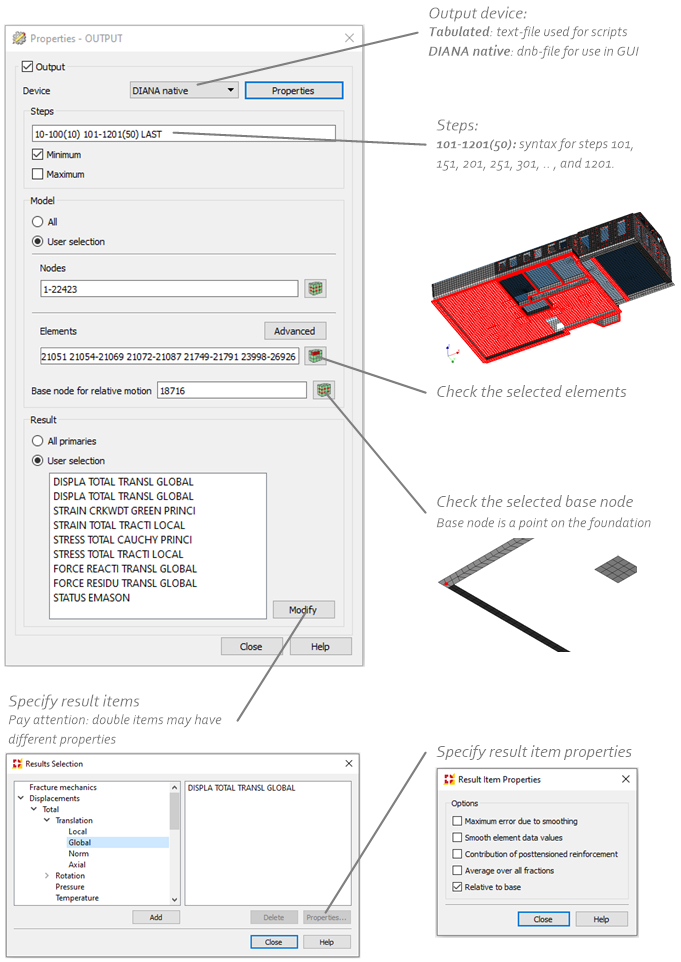
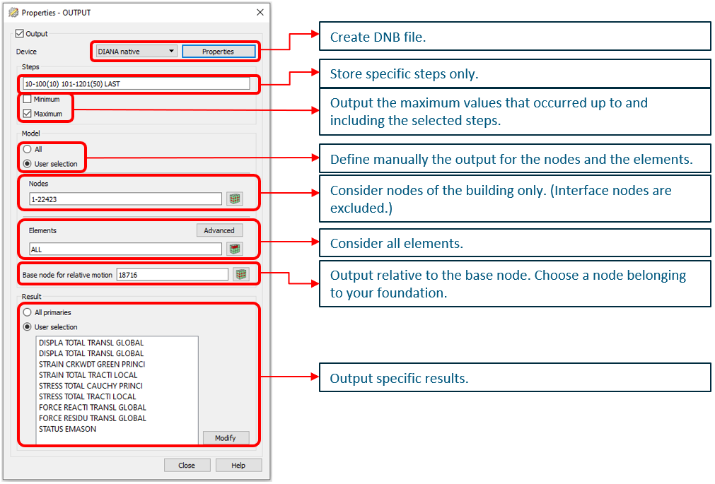
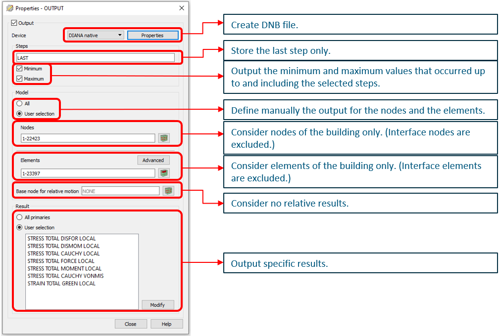
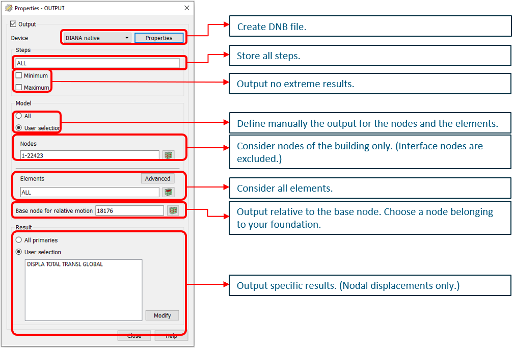
The output blocks 1 contain the general result items of the model. The output block 1A collects the maximum values up to the selected steps of the signal. The syntax for the dcf-file is:
BEGIN OUTPUT
  TEXT OUTPUT_1A_MAX
  BINARY
  FILE "SXXX_OUTPUT_1A_MAX"
  SELECT BASNOD 0
  SELECT NODES 'nodes building' /
  SELECT ELEMEN 'elements building' /
  SELECT STEPS 10-100(10) 101-1000(50) LAST / MAX
  DISPLA TOTAL TRANSL GLOBAL RELATI ON
  DISPLA TOTAL TRANSL GLOBAL
  STRAIN CRKWDT GREEN PRINCI INTPNT
  STRESS TOTAL CAUCHY PRINCI INTPNT
  STRESS TOTAL TRACTI LOCAL INTPNT
  STRAIN TOTAL TRACTI LOCAL INTPNT
  FORCE REACTI TRANSL GLOBAL
  FORCE RESIDU TRANSL GLOBAL
END OUTPUT
Note
CHECK BEFORE ANALYSIS:
All elements en nodes of building and connections should be selected.
Decide if output-block 1C is required.
Check if the signal length is correctly applied.
Check if base node is correctly selected.
The dcf commands can be checked in the DIANA GUI:
Output block 1B collects the minimum values of the output items up to the selected steps in the signal.
BEGIN OUTPUT
  TEXT OUTPUT_1B_MIN
  BINARY
  FILE "SXXX_OUTPUT_1B_MIN"
  SELECT BASNOD 0
  SELECT NODES 'nodes building' /
  SELECT ELEMEN 'elements building' /
  SELECT STEPS 10-100(10) 101-1000(50) LAST / MIN
  DISPLA TOTAL TRANSL GLOBAL RELATI ON
  STRAIN CRKWDT GREEN PRINCI INTPNT
  STRESS TOTAL CAUCHY PRINCI INTPNT
  STRESS TOTAL TRACTI LOCAL INTPNT
  STRAIN TOTAL TRACTI LOCAL INTPNT
  FORCE REACTI TRANSL GLOBAL
  FORCE RESIDU TRANSL GLOBAL
  STATUS EMASON
END OUTPUT
The nodes and the elements selected should contain only the nodes and elements of the building. For element output the results are assessed only in the integration points (INTPNT). By providing the base node the displacements and accelerations will be retrieved compared to that point. For VIIA this point should be selected on the foundation strip.
The dcf commands can be checked in the DIANA GUI:

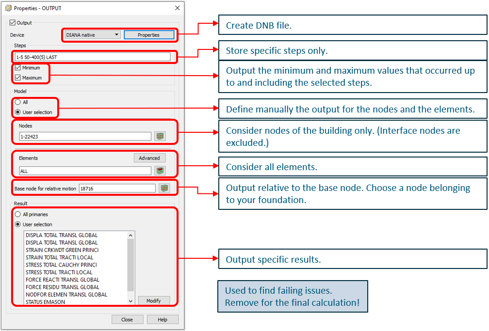
To get more data from the more intense parts of the signal the output-block 1C could be added to the dcf-file. This block is not added by default to improve for the analysis time.
BEGIN OUTPUT
  TEXT OUTPUT_1C
  BINARY
  FILE "SXXX_OUTPUT_1C"
  SELECT BASNOD 0
  SELECT NODES 'nodes building' /
  SELECT ELEMEN 'elements building' /
  SELECT STEPS 10- 1-5 50-400(5) LAST
  DISPLA TOTAL TRANSL GLOBAL RELATI ON
  DISPLA TOTAL TRANSL GLOBAL
  STRAIN CRKWDT GREEN PRINCI INTPNT
  STRESS TOTAL CAUCHY PRINCI INTPNT
  STRESS TOTAL TRACTI LOCAL INTPNT
  STRAIN TOTAL TRACTI LOCAL INTPNT
  FORCE REACTI TRANSL GLOBAL
  FORCE RESIDU TRANSL GLOBAL
END OUTPUT
The dcf commands can be checked in the DIANA GUI:
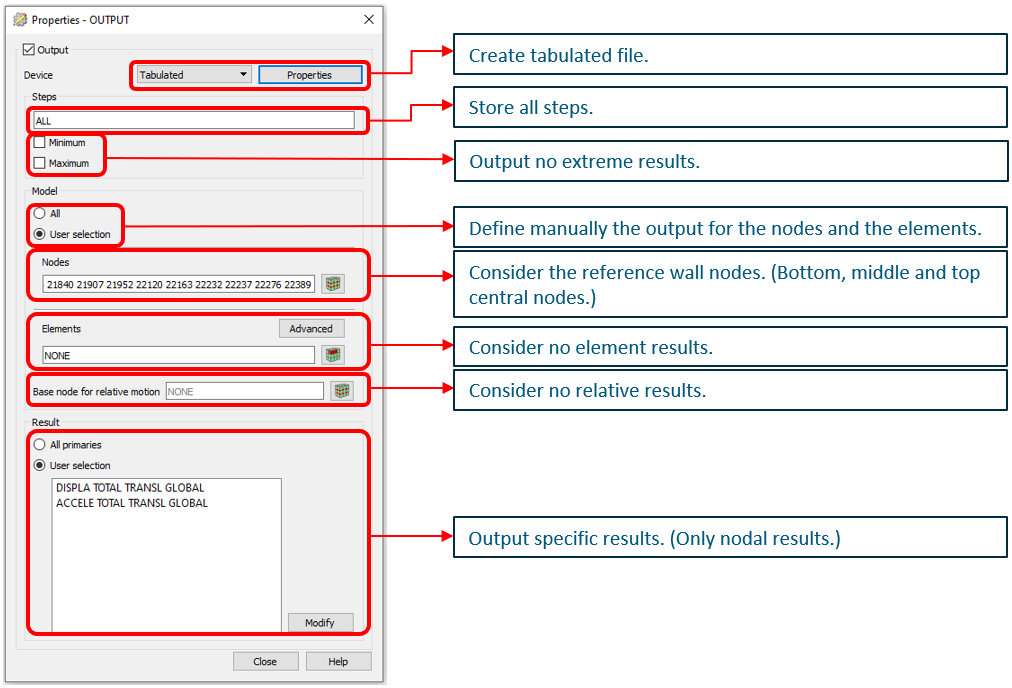
Block 2 - Wall displacements
To check the in-plane and out-of-plane behaviour of the walls the displacements and accelerations are collected on bottom, center and top of the wall for all time-steps and all walls in the fem-model. This output is written in a tabulated file to provide for automated result handling. Also for the assessment of the interstorey drift the bottom and top points of the walls are used.
BEGIN OUTPUT
  TEXT OUTPUT_2
  TABULA
  FILE "SXXX_OUTPUT_2"
  LAYOUT LINPAG 0
  SELECT NODES 'nodes of walls (bottom, mid and top)' /
  SELECT ELEMEN NONE /
  SELECT STEPS ALL /
  DISPLA TOTAL TRANSL GLOBAL X Y Z
END OUTPUT
The dcf commands can be checked in the DIANA GUI:
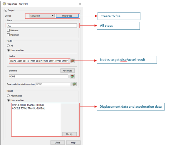
Block 3 - Acceleration graph
The output-block 3 is to collect the nodes for the acceleration plots.
BEGIN OUTPUT
  TEXT OUTPUT_3
  TABULA
  FILE "SXXX_OUTPUT_3"
  LAYOUT LINPAG 0
  SELECT NODES 'nodes of reference points' /
  SELECT ELEMEN NONE /
  SELECT STEPS ALL /
  DISPLA TOTAL TRANSL GLOBAL X Y Z
END OUTPUT
The dcf commands can be checked in the DIANA GUI:
Block 4 - Linear-elastic modelled elements
Some elements in the fem-model are modelled with linear-elastic material models. These elements need to be checked if they comply to the capacity of these materials. When the element is a strengthening measure the results are added to report for a next phase. It is important to check whether these forces allow for a proper design. The shallow foundation boundary interface elements are not included in this output-block.
Compliance check is performed on the minimum and maximum values of the complete analysis (last step).
BEGIN OUTPUT
  TEXT OUTPUT_4
  BINARY
  FILE "SXXX_OUTPUT_4"
  SELECT ELEMEN 'elements for linear elastic elements' /
  SELECT STEPS LAST / MIN MAX
  STRESS TOTAL DISFOR LOCAL XX YY ZZ XY YZ ZX
  STRESS TOTAL DISMOM LOCAL
  STRESS TOTAL CAUCHY LOCAL INTPNT XX YY ZZ XY YZ ZX
  STRESS TOTAL FORCE LOCAL X Y Z
  STRESS TOTAL MOMENT LOCAL
  STRESS TOTAL CAUCHY VONMIS INTPNT
  STRAIN TOTAL GREEN LOCAL INTPNT
END OUTPUT
The dcf commands can be checked in the DIANA GUI:
Output-block 4B is generated for linear structural interfaces in tabulated format. This output is used for the result handling on shear forces in the linear connections and L2-measures in the model.
BEGIN OUTPUT
  TEXT OUTPUT_4B
  TABULA
  FILE "SXXX_OUTPUT_4B"
  SELECT NODES 'nodes of linear structural interfaces' /
  SELECT ELEMEN 'elements of linear structural interfaces' /
  SELECT STEPS ALL
  STRAIN TOTAL TRACTI LOCAL INTPNT
  STRESS TOTAL TRACTI LOCAL INTPNT
END OUTPUT
Block 5 - Base shear
The base shear is required to plot in the final report. It gives insight in the building and can be used to check if the analysis is performed correctly. The required type of output depends on the type of foundation. Refer to the section of shallow foundations or pile foundations. In case of mixed foundation both output blocks should be applied.
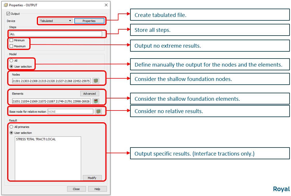
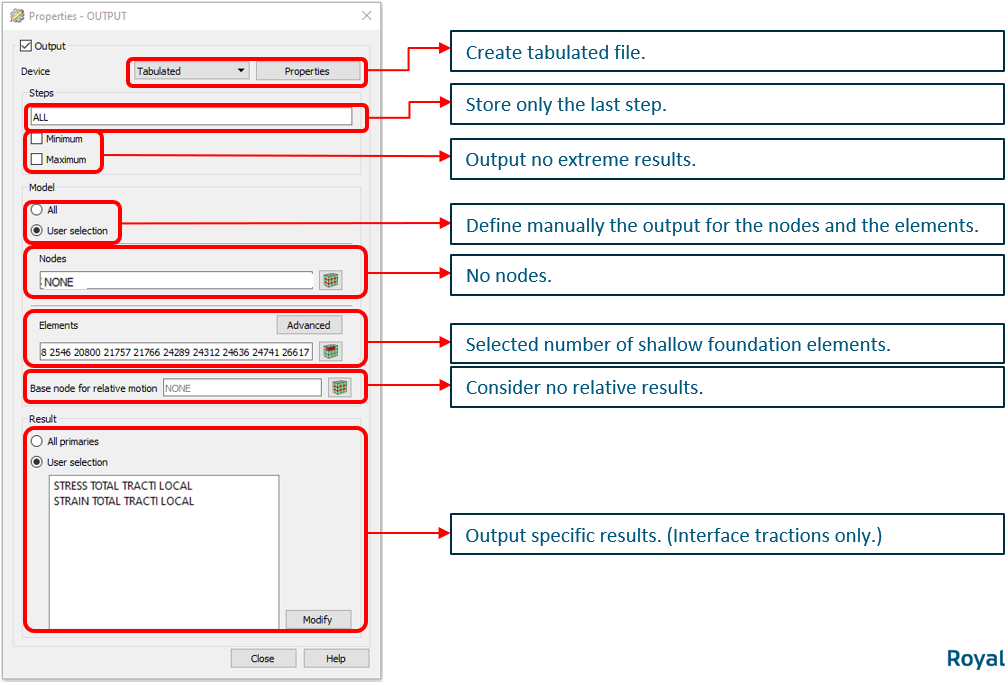
Shallow foundation
The base shear is calculated based on the stresses in the shallow foundation interface. The local axes should have been aligned. The output is requested for all time-steps. This output is also used to provide information to the geotechnical engineer (see next section).
BEGIN OUTPUT
  TEXT OUTPUT_5A
  TABULA
  FILE "SXXX_OUTPUT_5A"
  LAYOUT LINPAG 0
  SELECT ELEMEN 'elements shallow foundation interfaces' /
  SELECT STEPS ALL
  STRESS TOTAL TRACTI LOCAL CENTER
END OUTPUT
The result handling is automated for the default tabulated output.
Note
CHECK BEFORE ANALYSIS:
Check if axes of shallow foundation interface are aligned.
Check if all elements of the shallow foundation interface are selected.
The dcf commands can be checked in the DIANA GUI:
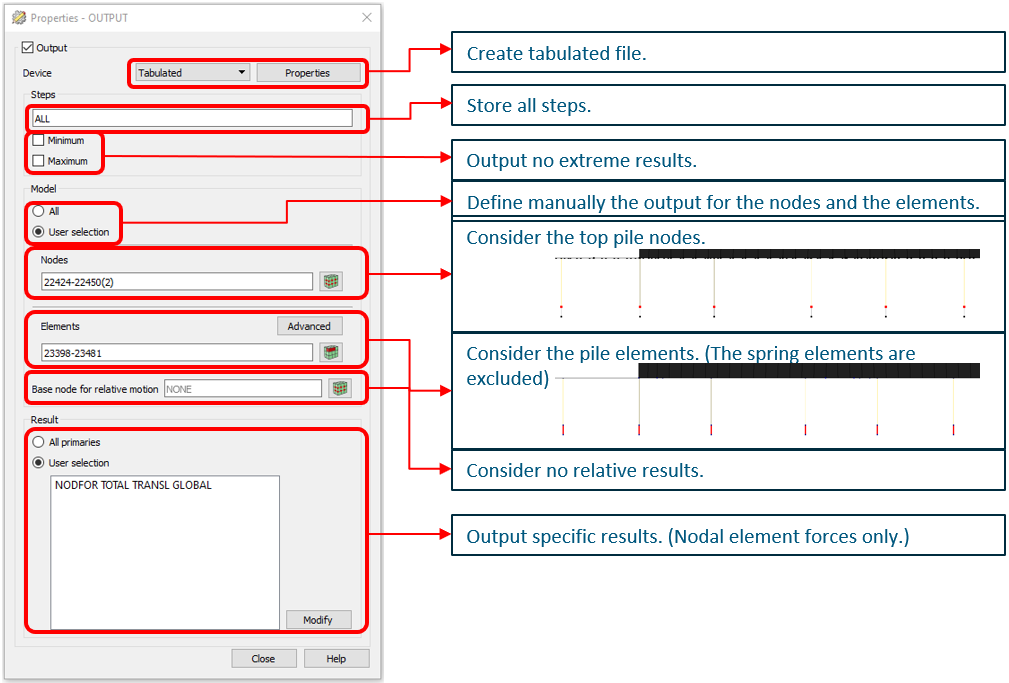
Pile foundation
The base shear is calculated based on the section forces of the beam element representing the foundation pile. The nodal force is collected for the beam element and the bottom node of it. This output is also used to provide information to the geotechnical engineer (see next section).
BEGIN OUTPUT
  TEXT OUTPUT_5B
  TABULA
  FILE "SXXX_OUTPUT_5B"
  LAYOUT LINPAG 0
  SELECT NODES 'Nodes at the bottom of the beam elements representing the foundation piles in the fem-model' /
  SELECT ELEMEN 'Elements of the beam elements representing the foundation piles in the fem-model' /
  SELECT STEPS ALL
  NODFOR TOTAL TRANSL GLOBAL X Y Z
END OUTPUT
The result handling is automated for the default tabulated output.
Note
CHECK BEFORE ANALYSIS:
Check if all piles are selected.
Check if only bottom nodes of beam elements are selected.
The dcf commands can be checked in the DIANA GUI:
Block - Movie
For visualisation of the building behaviour the movie output items are requested.
BEGIN OUTPUT
  TEXT OUTPUT_MOVIE
  BINARY
  FILE "SXXX_OUTPUT_MOVIE"
  SELECT NODES 'complete model' /
  SELECT STEPS ALL
  DISPLA TOTAL TRANSL GLOBAL X Y Z
END OUTPUT
The result handling is automated for the default tabulated output.
Note
CHECK BEFORE ANALYSIS:
Check if only nodes of the complete model are selected.
The dcf commands can be checked in the DIANA GUI:
Output for the geotechnical assessment
This section describes the output that is required by the geotechnical advisor for the assessment of the foundation.
Shallow foundation
For the flexbase shallow foundation analyses the following output items are requested:
Stresses in normal and 2 shear directions in the interface elements between foundation strip and soil (base):
Maximum stress values all time-steps of transient analysis
Minimum stress value all time-steps of transient analysis
Stress values after applying all loads in static situation existing building
Stress values after applying all loads in static situation strengthened building
Stress values at the post-seismic situation (last timestep) of strengthened building
To determine the last step of the analysis (the post-seismic situation), the acceleration of the base (soil) should be zero. By default we add 0.5 seconds to the signal, this assumption needs to be checked after the analysis.
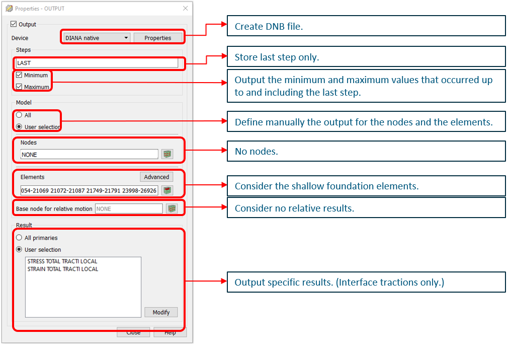
For the output items related to the maximum and minimum stresses in the transient analysis the syntax in the dcf-file should be:
BEGIN OUTPUT
    TEXT OUTPUT_GEO1
    BINARY
    FILE "SXXX_GEO1"
    SELECT STEPS LAST / MIN MAX
    SELECT ELEMEN 'elementensets shallow foundation interfaces' /
    STRESS TOTAL TRACTI LOCAL INTPNT
    STRAIN TOTAL TRACTI LOCAL INTPNT
END OUTPUT
The dcf commands can be checked in the DIANA GUI:
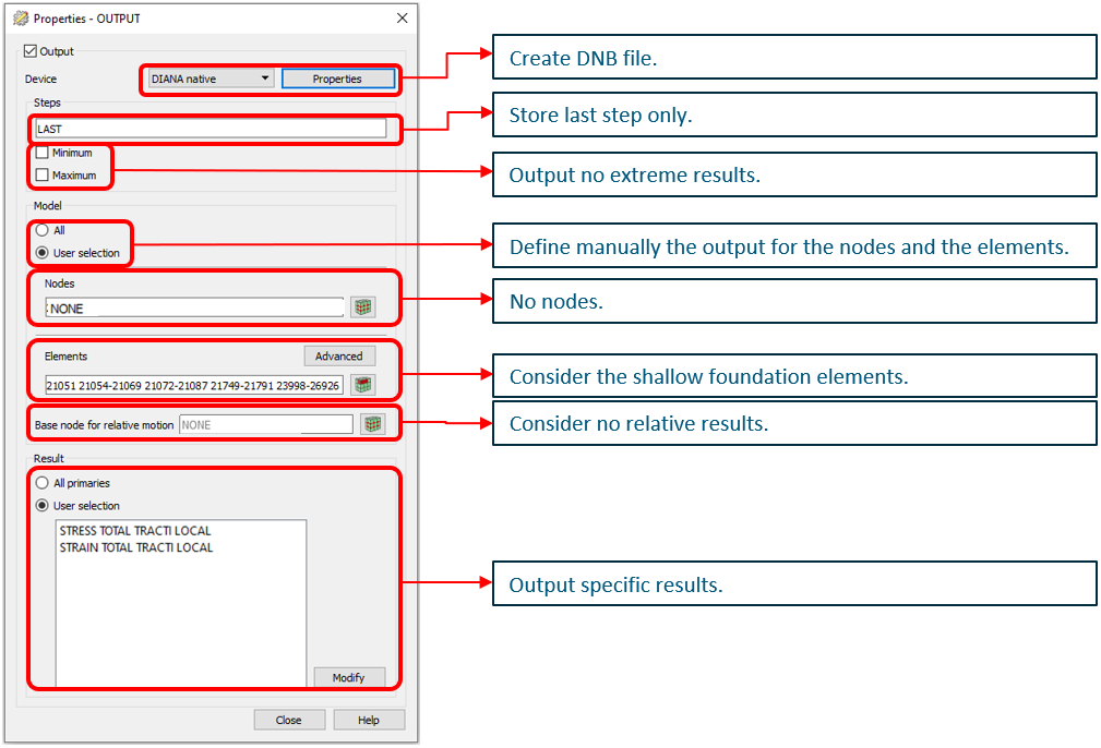
For the output items related to the post-seismic stresses in the transient analysis the syntax in the dcf-file should be:
BEGIN OUTPUT
    TEXT OUTPUT_GEO2
    BINARY
    FILE "SXXX_GEO2"
    SELECT STEPS LAST
    SELECT ELEMEN 'elementensets shallow foundation interfaces' /
    STRESS TOTAL TRACTI LOCAL INTPNT
    STRAIN TOTAL TRACTI LOCAL INTPNT
END OUTPUT
Note
CHECK BEFORE ANALYSIS:
Elements should contain the shallow foundation interface only.
The dcf commands can be checked in the DIANA GUI:
Additional information for the geotechnical advisor is retrieved from the output block 5. More information will be added here.
The output items in GEO1 and GEO2 are used to generate a picture with the strains and stresses in the shallow foundation interface. These pictures should be assessed for unexpected behaviour of the interface. It might help to allocate deficiencies in the foundation of the building. The picture should be sent to the geotechnical advisorm, but are not required to be added in the report.
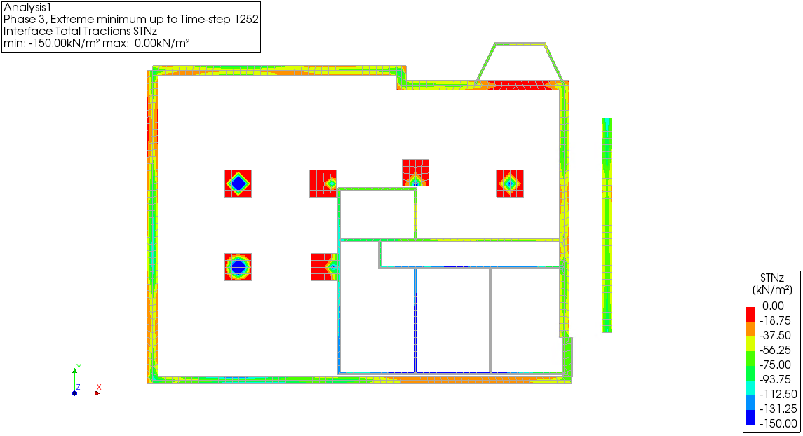
Figure - Example picture of the minimum normal stress in the shallow foundation in [kN/m2].
Note
Examples of unexpected behaviour:
Tensile stresses in the shallow foundation interface.
Compressive stresses exceeding the provided bearing capacity.
Excessive shear stresses in x- or y-direction.
The pictures could also demonstrate that the axes of the elements are not correctly alligned.
Reference output
It could be required to verify the behaviour of the shallow foundation interface. Therefore by default reference elements are selected randomly (but if the geotechnical advisor requests a specific point, that should be added in this output-item). This element is assessed in all time-steps and can be used to generate stress-strain diagrams to provide insight in the non-linear behaviour.
BEGIN OUTPUT
    TEXT OUTPUT_GEO_REF
    TABULATED
    FILE "SXXX_GEO_REF"
    LAYOUT LINPAG 0
    SELECT STEPS ALL
    SELECT ELEMEN 'list of (random) elements shallow foundation interfaces' /
    STRESS TOTAL TRACTI LOCAL INTPNT
    STRAIN TOTAL TRACTI LOCAL INTPNT
END OUTPUT
The dcf commands can be checked in the DIANA GUI:
Pile foundation
For the flexbase pile foundation analyses the following output items are requested:
Pile forces in normal and 2 shear directions in the beam element representing the pile:
Maximum force values over all time-steps of transient analysis
Minimum force values over all time-steps of transient analysis
Pile force values after applying all loads in static situation existing building
Pile force values after applying all loads in static situation strengthened building
Pile force values at the post-seismic situation (last timestep) of strengthened building
To determine the last step of the analysis (the post-seismic situation), the acceleration of the base (soil) should be zero. By default we add 0.5 seconds to the signal, this assumption needs to be checked after the analysis.
All the required information is already present in output block 5. Therefore no additional output is required in the dcf-file. More information will be added here.
Bugfixing in DIANA for DCF
Resume the calculation from last converged step
It is possible in DIANA to resume the analysis after a non-converged step or a forced stopped analysis. Then it is not required to restart the whole calculation to retrieve the load-history for instance. Resuming the analysis can be done from the last converged and saved time or load step. Therefore the command SAVE CONVER should have been added to the analysis.
Saving the converged time or load-step does however decreases the analysis time. That is why it is not set by default for VIIA project. Before restart the dcf-file must be updated in locations:
Remove the FILOS INITIA command (or replace with FILOS UNLOCK in case of a forced stopped analysis).
Add MODEL OFF and TYPE OFF at the start of the dcf-file.
Previously performed execute blocks should be removed.
Add RESTORE with the number of the last converged step between BEGIN STEPS and END STEPS.
Add APPEND in the output blocks.
For example assume that step 78 is the last converged step, then restart can be performed with:
>>> BEGIN TIME
        BEGIN STEPS
            EXPLIC SIZES 0.0 0.01(1050)
            RESTORE 78
            SAVE CONVER
        END STEPS
    END TIME
Eigenvalue analysis
Before starting the analysis, or during the analysis, an eigenvalue analysis can be performed based on the last converged step. This might give insight in the weak parts of the building during the calculation. Remember when the analysis is started with a saved filos file, you do not have to initiate a new one. See the following example:
*EIGEN LABEL="Structural eigenvalue"
  MODEL OFF
  TYPE FREEVI STIFFN NONLIN STRESS PHASE
  BEGIN EXECUT
      METHOD FEAST
      NMODES 200
      FMIN 2
      FMAX 20
      EMIN 0
      EMAX 1
  END EXECUT
  BEGIN OUTPUT
      TEXT "Output eigenvalue analysis"
      BINARY
      SELECT MODES ALL /
  END OUTPUT
*END
Adaptive stepsize
Adaptive load increments applies an automated reduction of step-size for a non-converging step. Advantage of this procedure is that instead of continuing with the analysis in the wrong direction and resulting in divergence, it could solve a numerical issue with smaller steps and continue through the non-linear point. The following syntax can be used:
BEGIN EXECUT
  TEXT "Seismic non-linear"
  BEGIN TIME
    BEGIN STEPS
      BEGIN AUTOMA
        SIZES 10
        MAXSIZ 1e-3
        MINSIZ 1e-10
      END AUTOMA
      SAVE 100-2010(100)
    END STEPS
  END TIME
In the example the total step size depends on the signal length of 10 seconds. For the maximum step-size it is advised to use the normal step size (10 ms).
Change iteration procedure during the analysis
When the SWITCH command is applied in the iteration proces the analysis will change iteration method after any diverging, non-converging or error. First regular Newton Raphson is applied, then it will be switched to Secant and then to linear. Drawback is that is does not switch back to the original iteration method after convergence in the next step. The maximum number of iterations is not adjusted when switching.
BEGIN ITERAT
  MAXITE 20
  METHOD NEWTON
  SWITCH
  BEGIN CONVER
    FORCE OFF
    DISPLA OFF
    BEGIN ENERGY
      TOLABT 1000
      CONTIN
    END ENERGY
  END CONVER
END ITERAT
Warning
Because of unclear results, it is not allowed in VIIA to use this procedure in analyses that are used for the assessment of the object.
NLPO specifics
This section contains explanation of the items in the dcf-file that are specific for the NLPO procedure. If the setting is not different then the procedure for NLTH, refer to the sections above.
Initialisation, see Initialisation.
Phasing, see First phase - apply self weight.
First analysis block
The next part in the dcf-file provides the analysis of the weight of the current phase. This analysis is ‘structural nonlinear’.
*EIGEN LABEL="Structural eigenvalue"
*EIGEN LABEL=”Structural eigenvalue”
The module eigen is started to perform an eigen value analysis on the current state of the model.
Evaluate model, see Evaluate model.
Nonlinear effects
Default settings for VIIA:
>>> TYPE FREEVI STIFFN LINEAR STRESS OFF
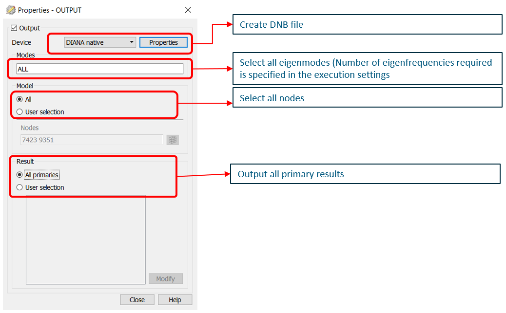
Execute block
Default settings for VIIA:
BEGIN EXECUT
  PARDIS
  MAXTHR 4
  NMODES 20
  FSHIFT 0
  MAXITE 30
Note
CHECK BEFORE ANALYSIS:
Check if the number of eigenmodes to contain the dominant eigen frequency from A7 analysis.
MAXTHR 4
The analysis is performed simultaneously on maximum of 4 threads. This setting has proven to be the most efficient
value in the VIIA project on the VIIA servers. When this is not specified, the maximum available threads are used.
Pay attention on the servers! When there are less threads available the analysis will delay.
NMODES 20
Select the number of eigenfrequencies such that the dominant eigen frequency is present (Based on the A7 analysis).
MAXITE 30
Maximum number of iterations is set to 30.
Output settings
The output block contain the output for the eigen frequency analysis. These result items are the expressed as a global translational total displacement, or the shapes of the eigenmode. The displacements are not real values but a relative displacement, showing the shape of the mode.
Pushover analysis block
The next part in the dcf-file provides the analysis of the pushover. This analysis is ‘structural nonlinear’.
*NONLIN LABEL="Nonlinear Pushover"
Evaluate model, see Evaluate model.
Nonlinear effects
Compared to the NLTH the setting for transient nonlinear effects is switched off. Default settings for VIIA:
BEGIN TYPE
  BEGIN GEOMET
    NCLOAD OFF
    NLPREB OFF
  END GEOMET
  TRANSI OFF
END TYPE
BEGIN / END TYPE
Specifies the type of analysis.
GEOMET
When applying this command the geometrical non-linearity is taken into account defined by Lagrange formula.
NCLOAD OFF
Option for non-conservative load-cases is not used for VIIA.
NLPREB OFF
Option for subsequent Euler perturbation analysis with pre-buckling nonlinearity is not used for VIIA.
Execute block - SW
Default settings for VIIA:
BEGIN EXECUT
  TEXT SW
  BEGIN LOAD
    LOADNR 1
    BEGIN STEPS
      BEGIN EXPLIC
        SIZES 0.5 0.5
        ARCLEN OFF
      END EXPLIC
    END STEPS
  END LOAD
Load steps, see Execute block - Start.
  BEGIN ITERAT
    METHOD NEWTON
    LINESE OFF
    BEGIN CONVER
      SIMULT ON
      BEGIN FORCE
        TOLCON 0.001
        TOLABT 1e+17
        CONTIN
      END FORCE
      BEGIN DISPLA
        TOLCON 0.001
        TOLABT 1e+17
        CONTIN
      END DISPLA
    END CONVER
  END ITERAT
END EXECUT