How to create the engineering report
This how-to guide provides comprehensive instructions for creating the engineering report, referred to by the client as the ‘TVA’ (Technisch Versterkings Advies). The phases of the analysis-specific protocols outline various reporting steps. This guide is designed to support engineers in successfully navigating these steps.
With exception of appendix C3 (description of the model) it is recommended to start reporting at the end of the assessment.
To start, this guide offers an overview of the reporting process and provides general instructions. Subsequently, it
delves into specific sections detailing the information to be included in each part/appendix of the report. The final
section of this guide concerns the use of the function viia_create_report().
Note
In the engineering report, sections related to the current or existing state are commonly labeled as ‘BSC’ (Beoordeling Seismische Capaciteit) or assessment of seismic capacity; the strengthened state and its evaluation are denoted as ‘TVA’ (Technisch Versterkings Advies) or technical retrofit advice. It’s important to note that the overarching final report will always be titled ‘TVA’, regardless of whether strengthening measures are advised or not. This naming convention may appear counterintuitive, so pay attention to avoid any potential confusion.”

Overview of the reporting process
The goal of the templates is to provide a guideline for you to follow, and thus accommodates for the most-likely scenarios; in case you find your object deviating from what is covered in the template, you are expected (and encouraged) to make the appropriate adaptations; the template indicates what should – at minimum – be reported. Ask yourself: does my report sufficiently explain the seismic assessment I performed? what would I need to include in an engineering report if I would write it from scratch?
The following paragraphs summarise the complete reporting process, in order of occurrence (hence the non-alphabetical order).
Appendix C3 - Structural System The first reporting step concerns the creation of Appendix C3 (Step R1 of Phase 1). This appendix provides an overview of the structural system. For NLTH objects, this is appendix can be automatically generated, which is done after finishing the modelscript. This appendix will be reviewed during the C2 Model Check. For a more detailed explanation on Appendix C3, see this section.
The steps below are executed as a part of (NLTH) Step R2 of Phase 5 or (REF) Phase 6.
Appendix C4 - Foundation The assessment of the foundation is reported in appendix C4. In case your building requires assessment by a geo-engineer, you do not have to draft this appendix. Otherwise, you are expected to draft this appendix using the template that is generated in the reportscript.
Appendix C1 - Seismic Assessment The bulk of the seismic assessment of your object is reported in Appendix C1. The contents should be generated completely. Hence it is advised to generate the report after finalising the NLTH analyses required for the engineering report. The appendix describes the analysis method, seismic assessment of the existing and potentially strengthened situation, and the recommended strengthening measures. Various note-blocks, comments and examples are there to guide you in drafting the report. However, please make the changes appropriate for your specific building. For NLTH object, the result pictures for non-governing signals are collected and uploaded to Box as an compressed folder.
Appendix C2 - Input/Output of Analyses The template of Appendix C2 is only a cover page. To this cover page, you can append any pages of in- or output of the analyses that you performed. Primarily, this will be the in- and output of the L4-sheets, used for NLKA, but you are free to add any calculations that you made. Whatever is necessary for your report. Do not forget to put the appropriate references to C2 in the other appendices (as is done in the template: see the OOP assessment of NSCE wall)
Appendix A1 - Drawings Existing Situation The drawings of the existing situation will be added to the appendix A1. With the report generation tool the engineer will have a prefilled cover page with the general information. The engineer should add it (as a pdf) to the correct box-folder, the editors will add the drawings of the existing situation. For the full procedure regarding drawings by the draftsman, see LINK Workflow Drawings & LINK Presentation Drawings MOVED TO SHAREPOINT.
Appendix A2 - Drawings Strengthened Situation After the measure meeting, the engineer prepares the frontpage for this annex and the editor will later add the drawings created by the draftsman.
Appendix A3 - Details Retrofitting The action sheets of the proposed measures are added to the appendix A3. The measures are retrieved from MYVIIA and the corresponding action sheets are downloaded from the GMC. With the report generation tool, you will get the A3 appendix file (as a pdf) with all the action sheets appended to the cover page.
TVA Main report The TVA main report contains general information on your building, the used references, and a conclusion. The document should be drafted using the template. In contrast to the other templates, non-highlighted text should generally not be changed. If for some object-specific reason, you think this is required, discuss this with your lead engineer.
Translated information for ‘Beoordelingsrapport’ After finishing the engineering report, you draft the translated information for the Beoordelingsrapport (formerly known as EVVA), using the appropriate template. If you dont have strengthening, you need to translate the structural setup. In case of strengthening you add the drawings of the measures and the pictures of the measures including some questions on the application (no need to add the explanation of the structural setup).
Zip-file non-governing signals Create a zip-file with the results of the non-governing signals. This file should be added in the folder with the final deliverables.
Final Deliverables
If no strengthening is required, the drafted appendices should be stripped of all non-appropriate text related to strengthening and conclusions should be drawn noting that the seismic capacity of the existing situation is already sufficient. If strengthening measures are required, all text in the documents should be modified to reflect this.
In the end, all documents should be reviewed by one of your peers and by your lead engineer, as documented in Step C5.
After the reviews by the peer and lead engineer, the structural engineer shall produce a ‘clean’ final TVA-Report, i.e. no textual corrections (switch off ‘track changes’ in the Word-review module after finalising textual corrections) or remaining comments (in case of ambiguities, discuss these with the lead-engineer directly). The report title and filename need to correspond to the example below. In case of subdivisions of objects (i.e. ‘house’ and ‘barn’), an additional underscore shall be used to create unique report titles/filenames.
Format: VIIA_{object code}_TVA
Example: VIIA_795M_TVA (VIIA_795M_TVA.docx)
Example subdivision: VIIA_795M_TVA_Woning, VIIA_795M_TVA_Schuur
On delivery (from engineering), the TVA-report shall be present as a single docx-file in the ‘01 Concept’-folder; see Figure 1 for an example. Appendices can be stored in a sub-folder ‘Appendices’. Other files (less relevant for editors or project leader) may be stored in other folders (i.e. ‘Workfiles’, ‘Internal reviews’, et cetera).
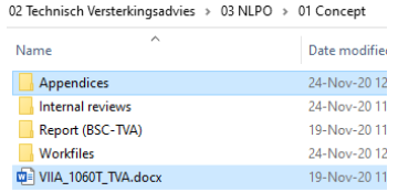
Figure 183 Required storage of TVA-report and Appendices.
Reporting Instruction
For each of the required documents, a subsection below will elaborated on its content, requirements, examples, and the functionalities incorporated in the viiaPackage.
Note
The Reporting Taskforce aims to provide as much relevant examples and text as possible. However, it is expected of the engineer that he/she treats reporting with scrutiny and adds all significant information. Please pay close attention to the notes - containing instructions/remarks/advice - present throughout the templates in the blue text boxes.
The templates of some appendices can be used for all analysis methods. For these, “ALL” has been included in the document name. Other appendices may have separate templates for the different analysis methods, in which case e.g. “NLPO” or “NLTH_MRS” has been included in the document name.
Most templates contain notes and highlighted text providing instruction and examples for the engineer to follow (see Figure 3).
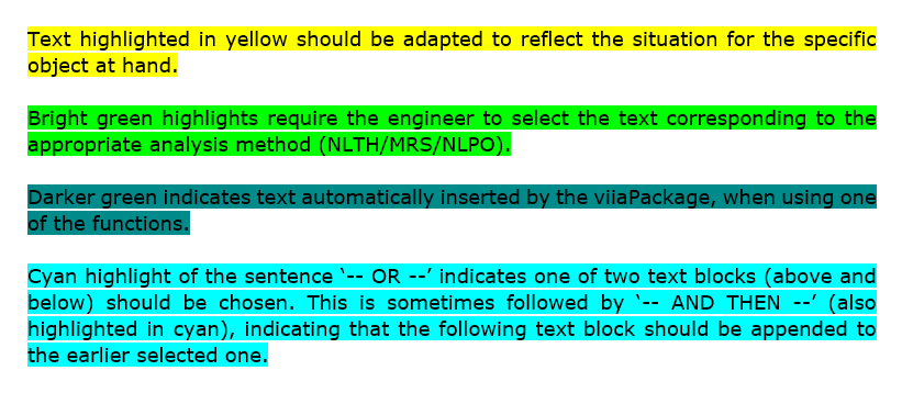
Figure 184 Different highlights and their meaning.
The figures in the report should be clear and presented in a large (page-wide if possible) and well-readable format. When no strengthening measures are required, several chapters/sections/figures can be removed from the templates: consult the sections below and the notes provided in the templates for specific instructions.
Selecting Engineering Report Template Version
The template version which should be used for the engineering report depends on the analysis method and tender specification of your object (which you can find on MYVIIA, see Figure 2). Table 1 shows which tender specification correspond to which template versions. The templates for the most recent tender specifications are part of the viiaPackage and are used in the reportscript, which will select the appropriate templates based on the information on MYVIIA.
Note
If you are not sure which template version you should use or no template exists: please contact Kees van Essen.
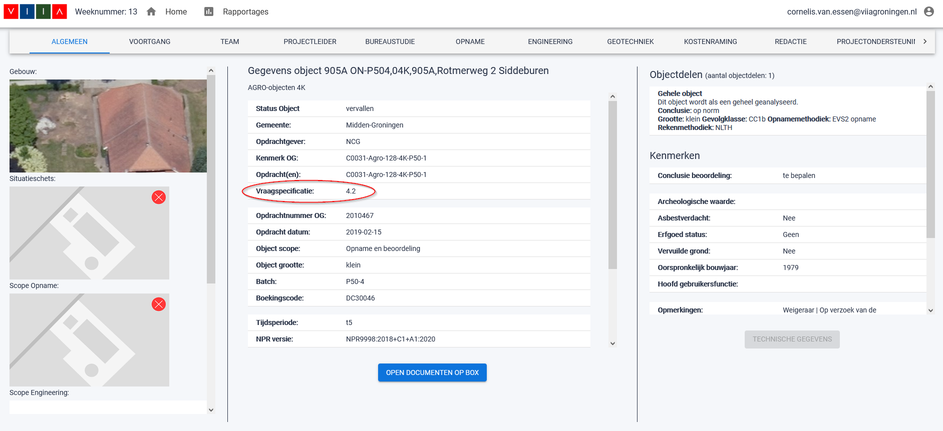
Figure 185 Tender specification (vraagspecificatie) on MYVIIA.
Tender specification |
ER Template Version |
|---|---|
4.2 |
4.2 |
5.0 & 5.2 |
5.0_5.2 |
5.3 |
5.3 |
Others |
7.1 |
Responsibilities
Discipline engineering (structural & geo) is ultimately responsible for appendices A, B, and C; the table below provides an overview. Additionally, the Issuelog (F), BKCL (D2), and ‘Translated information for the EVVA’ should be created by the structural engineer. Take note: not all appendices are required for each object, especially if it concerns a ‘Praktijkaanpak’ object.
Appendix |
Responsible |
Contents |
|---|---|---|
A1-A3 |
Structural engineer |
Drawings |
B1-B4 & C4 |
Geotechnical engineer |
Geotechnical Data and Foundation |
C1-C3 |
Structural engineer |
Seismic Assessment |
D1-D3 |
Project leader |
Building Data |
E1-E3 |
Project leader |
Cost Estimate (Kostenraming) |
F |
Project leader |
Issuelog |
G |
Project leader |
Report Internal Quality Control |
H |
Project leader |
Structural Validation Checklist Detached Barns |
Appendix C3 - Description of Finite Element Model / Structural System
Appendix C3 consists of a detailed description of the FEM model. The list below (which might not be conclusive for all objects) provides an overview of the components documented in this appendix.
An example of Appendix C3 is available here: LINK.
Warning
The generated document is merely a draft! Carefully review every drawing and make sure that all the information in them is correct. Furthermore, delete blank pages, update captions, add descriptions for line masses, etc. Also follow the instructions in the template! The structural engineer is responsible for the quality of the report delivered to the client. When in doubt, discuss with your lead engineer.
Note
Connections are created in the mainscript, and not in the modelscript. Therefore, the model plots of
the connections are not part of the appendix C3 draft created in the Step R2: Reporting NSCE assessment. These images have to be
generated in the mainscript by running the function
viia_create_model_plots() after the creation of connections. An example
of these images is available here: MOVED TO SHAREPOINT. The images
of connections created by the viiaPackage may not include all the connections that are present in your building. If
that is indeed the case, you need to manually adjust the images to ensure that all connections are represented
in the images.
The pictures that are used for this appendix must be stored in the folder ‘Appendix Pictures’, and in order to be inserted automatically in appendix C3, the picture files must follow a certain naming convention: {section_name} - {picture_name}.{png/jpg/etc..}. The available section names are defined in the template and determine which pictures can be added automatically to Appendix C3. E.g. if you want to add a picture of the foundation details, simply call it ‘Foundations - Foundation details.png’ and put it in the ‘Appendix Pictures’ folder.
Warning
Currently, the pictures do not always scale well for large buildings, especially if the building is significantly longer in one direction than the other. Readability issues may happen if the building is longer than 30 meter in the x-direction or 20 meters in the y-direction. So take a close look at the generated pictures in the end and assess whether or not the quality and readability of the pictures are sufficient. If you encounter such issues, report it as a bug and attach your modelscript so that the automation team can improve it in the future.
Automated Reporting by viiaPackage
The function viia_create_report() has been developed to assist the engineer with
creating the report. By calling the function in the reportscript, the TVA-report and the appendices are generated
and various data is inserted; the appropriate templates are selected based on the vraagspecificatie listed in the
MYVIIA-portal. The function uses different sources to compose the report. It collects information on the model from the
model json, it collects analysis data from the engineering database, and it collects pictures and graphs from the
analysis folders. It also connects to the GMC API to retrieve measure sheets, for which make sure that your GMC
credentials are included in the user_config.py file, you have access rights for the GMC API and that all measures
are added in MYVIIA first. It is important that the folders are named and located to conform with viiaPackage
convention.
folders = project.viia_prepare_for_engineering_report(governing_analysis=governing_analysis)

project.viia_create_report(governing_analysis=governing_analysis, input_folders=folders)
Above is shown the input for the report function. The user should select which signal is governing (check the results and assess which signal is most critical). A proper setup of your workfolder is important in order to use the reporting function. Before you use the function, please check if the folders listed below are present in your work folder. Figure 6 shows the required folder setup for NLTH. The folders are selected with a separate python function.
‘A7’, ‘A10’, ‘A12’ (for NLTH)
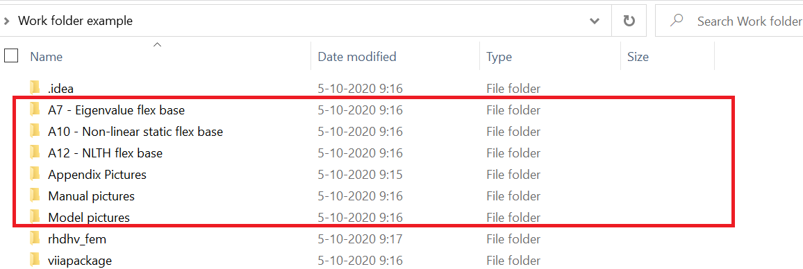
Figure 186 NLTH folder setup.
When running the reportscript the automated function will collect the required folders and will notify the user which folders are used in the generation of the report. It can be that the user would like to change a certain folder (for example when you have multiple trial analyses for strengthening measures). The defaults can be overruled. This is shown in the following example.
folders = project.viia_prepare_for_engineering_report(
    governing_analysis=governing_analysis,
    folders_a12={'S7': r'C/your_A12_folder'})
Manual Images
The ‘Manual Images’ folder is created by the viiaPackage contains several figures for the TVA document; these images are extracted from MYVIIA by the viiaPackage. An example of the Manual Images folder is shown in Figure 7. For NLTH-objects, the required images are automatically inserted in the document. For template version 6.0, only the image of the scope is inserted into the report.
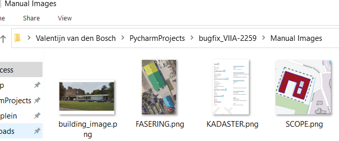
Figure 187 Manual images folder.
Currently, figures listed in the table below can be automatically added into report. Before using the reporting function, please generate and save these figures with the given names in the manual images folder.
Analysis Folders
The results of the eigenvalue analysis (A7) and non-linear static analysis (A10) using the governing signal have to be reported in HowToReport_AppendixResultsAnalysis-label. Running these analysis in DIANA will automatically create folders ‘A7 - Eigenvalue flex base/datetime_version’ and ‘A10 - Non-linear static flex base/datetime_version’ respectively; the required images are generated and stored in these folders as well.
The results of the seismic analysis (A12) using the governing signal should also be reported in Appendix C4; the results
using the non-governing signals should be reported in HowToReport_AppendixResultsAnalysisNG-label.
The appropriate contour plots for these appendices can be generated by running
_viia_results() (in Python). This will generate contour plots and store them in folder
‘A12 - NLTH flex base/SX/datetime_version’.
Running viia_create_report() will get the appropriate images from the folders
mentioned above and insert them in the report. If certain images have not been generated by the viiaPackage
automatically, you can manually make these images and save them with the appropriate name.
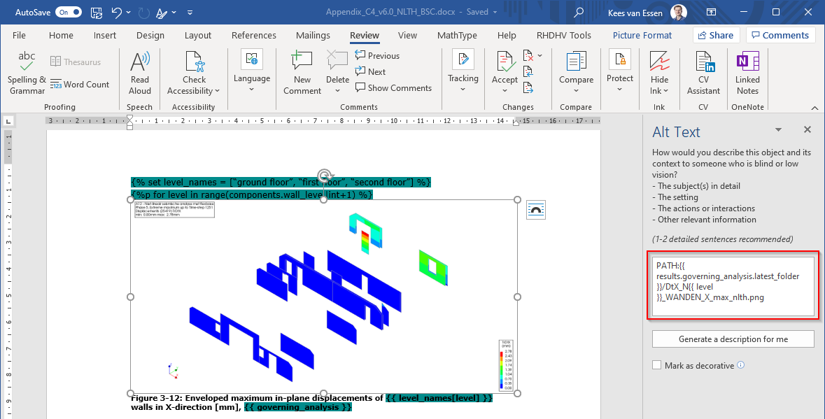
Figure 188 Alt text of figure in MS word.
Appendix Pictures
The ‘Appendix Pictures’ folder contains the figures for Appendix C3. Consult the instruction for the functionalities of the viiaPackage for this appendix. An example of the appendix pictures folder is shown in Figure 10.
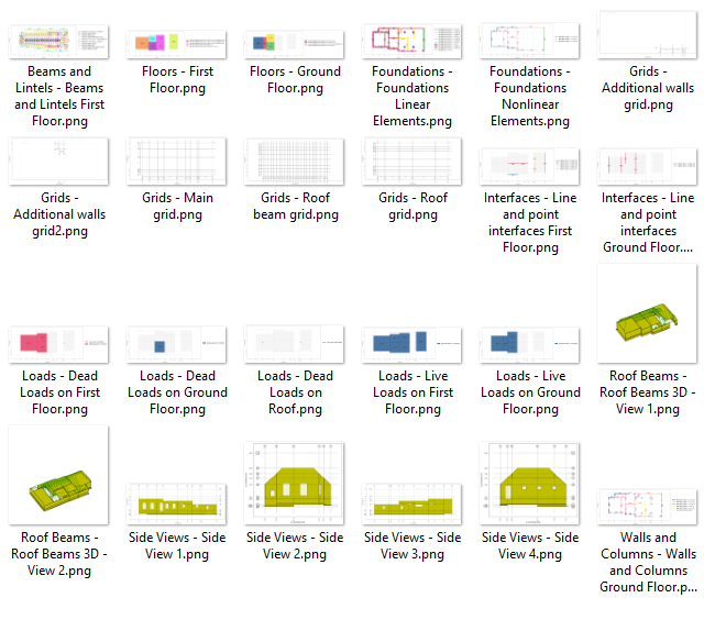
Figure 189 Appendix pictures folder.