How to create pictures and movies
Pictures and movies visualise the impact of a seismic loading on the building. You should realise that the client will only receive the engineering report (TVA) and will be focussing on the pictures in that report. Therefore the pictures should be clear and provide the needed information. The movies are of use for our own understanding of the behaviour of the building and should be presented in team meetings.
The results of the analysis need to be reported in the engineering report. There are different types of pictures that need to be created to give insight in the analysis:
Picture and Movie types |
|
|---|---|
Result pictures |
Representation of a certain output item or analysis result. |
Movie (optional) |
Representation of a selection of output items in video format. |
Model pictures (optional) |
3D visualisation of the materialisation and phasing of the FEM model. Replaced by Appendix C3. |
The procedure to create pictures consists of the following parts and/or functions that can be found in the results
module.
Result pictures
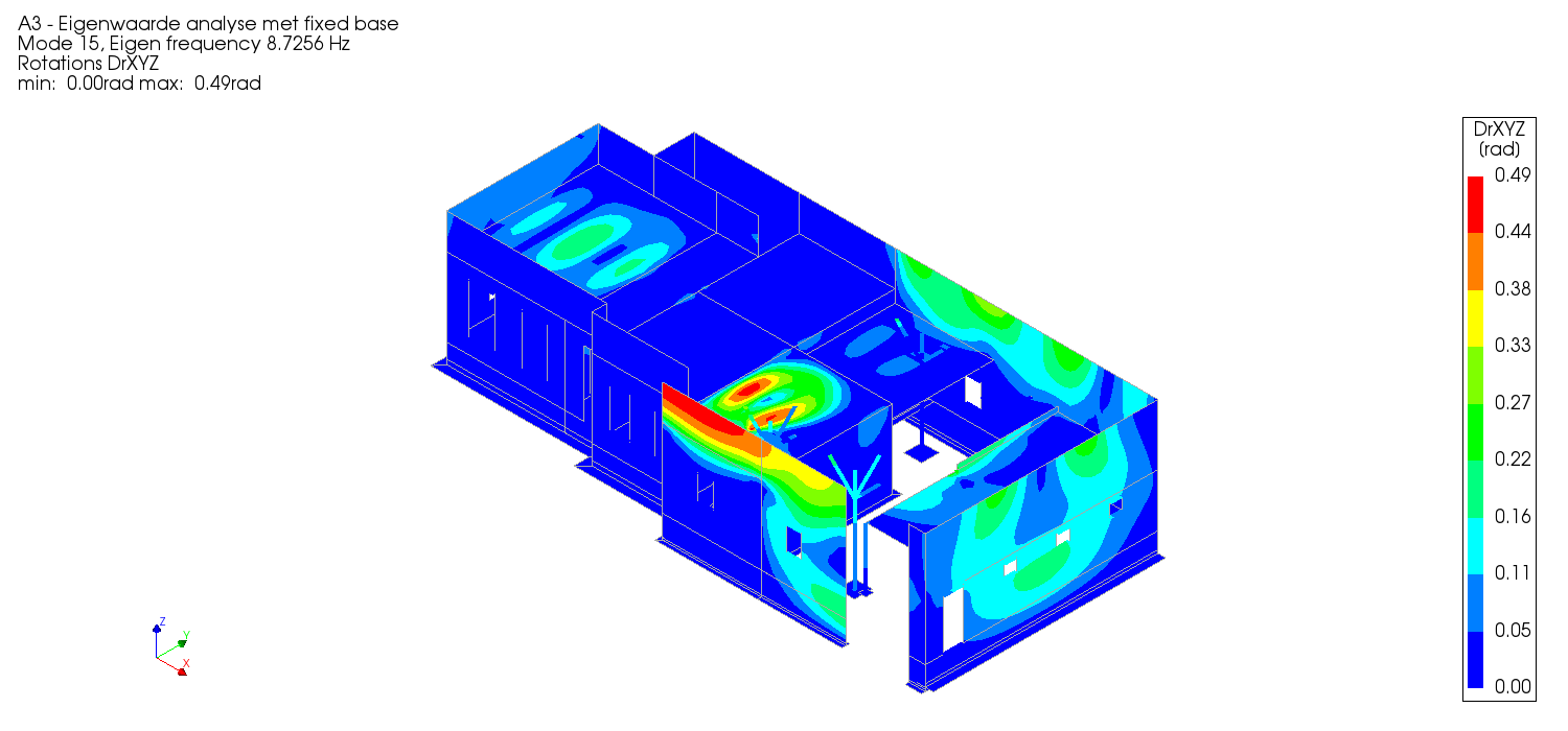
The result pictures are a representation of a certain output item or analysis result. These pictures include convergence graphs, base shear graphs, wall displacement graphs, acceleration graphs and result pictures of output items (with and without limits). These pictures can be generated using the resultscript.
Refer to How to use the result-script for NLTH for instruction and elaboration on the resultscript.
An example result picture is shown below:
Movie (Optional)
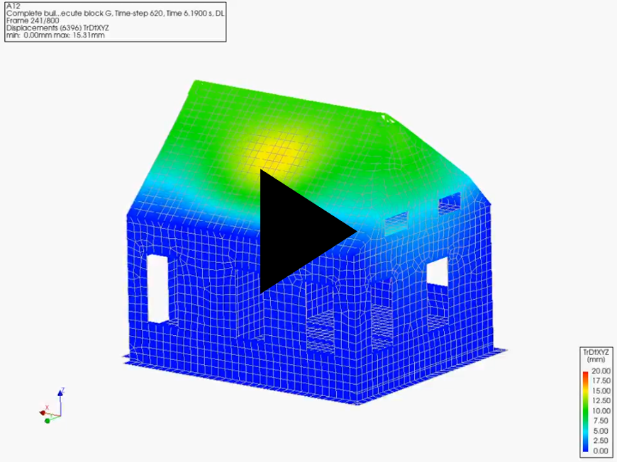
A movie can be made to represent the progression of an output item over a set of result cases. For example, a movie can be made of the displacements in an NLTH (A4/A12/A15) analysis, using the OUTPUT_MOVIE output block. These videos are not sent to the client, but can serve as a way for the engineer to understand the behaviour of the model.
Functions in the viiapackage related to the generation of movies are deprecated, which means that the recommended method for movie generation is to use the DIANA GUI directly.
Important settings to create readable movies:
Show the deformed mesh with free-face edges
Enable absolute deformation with a scaling factor (for example 10)
Fix the legend to be specified values (optionally use a continuous color scale)
Change the number of frames generated (at least the amount of timesteps/resultcases selected)
Change the number of frames per second when saving the movie

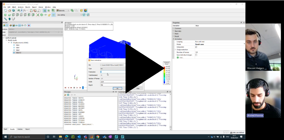
The following video shows a step-by-step introduction into making a movie in DIANA, of displacements in an NLTH (A4/A12/A15) analysis using the OUTPUT_MOVIE output block:
An example movie is shown below:
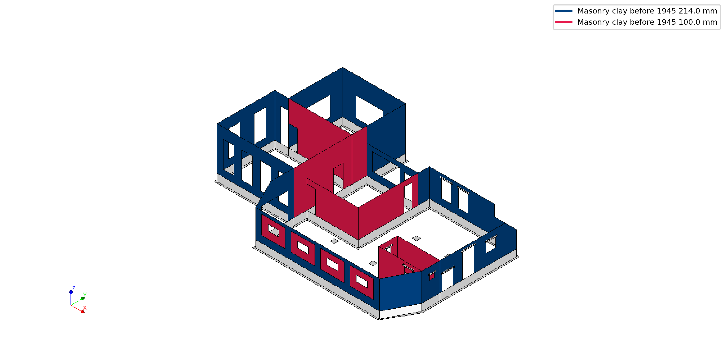
Model pictures (optional)
The model pictures are 3D visualisations of the materialisation and phasing of the FEM model. The model pictures are no longer part of the workflow and are no longer added to the report. The model pictures are replaced by the pictures in Appendix C3. Refer to Appendix C3 - Description of Finite Element Model / Structural System for more information about Appendix C3.
An increased amount of bugs due to an updated codebase might occur when creating the model pictures.
The model pictures could be generated by the function after creating the dat-file for the model:
project.viia_model_pictures()
All the information is gained by viiapackage.pictures.model_pictures.model_pictures.viia_create_model_pictures(),
the default view and render settings are set in this function as well as the shapes, their colours and a legend.
An example model picture is shown below: