3. Phase 2 - Calculation phase
The following seismic assessments needs to be performed:
In plane (IP) and out-of-plane assessment (OOP).
Assessment diaphragm action floors.
Assessment diaphragm action roofs.
Assessment of connections.
Assessment of NSCE’s.
Geotechnical assessment.
The IP and OOP assessment is performed by means of the SLaMA-tool.
3.1. SLaMA-tool
The SLaMA-tool performs in-plane and out-of-plane checks for masonry walls of single-storey buildings having wooden or concrete floors and shallow foundations in a systematic and mostly automated fashion; upon the entry of the material properties, the geometrical parameters describing a wall and the bearing characteristics of the floors, roofs, gables, and other loads, a capacity-demand curve is produced for each wall.
Note
- To get started with the SLaMA-tool:
Make sure you always copy the correct version of the SLaMA-tool into the desired directory.
To execute the script, type python src in the Terminal and press Enter to execute them. The SlaMA-tool will be displayed as a result.
For technical information, see the SLaMA-tool manual as presented in Annex B.
Points of attention:
The SLaMA tool performs individual wall strength- and deformation evaluations on the precondition that floor diaphragms are flexible and separate walls are therefore de-coupled. The engineer shall take proper notion of the fact that this may not always be a correct assumption, as it may generate unsafe results in specific cases. A sensitivity-analysis may be required in case floor diaphragms act more rigid than assumed.
The SLaMA-tool evaluates flexible floor diaphragms based on their ability to transfer loads to PSSE’s and maximum allowable deformations.
3.2. Dealing with cavity walls
A flowchart is presented below showing how to determine if the effective cavity ties are present, and what the influence is on the calculation.
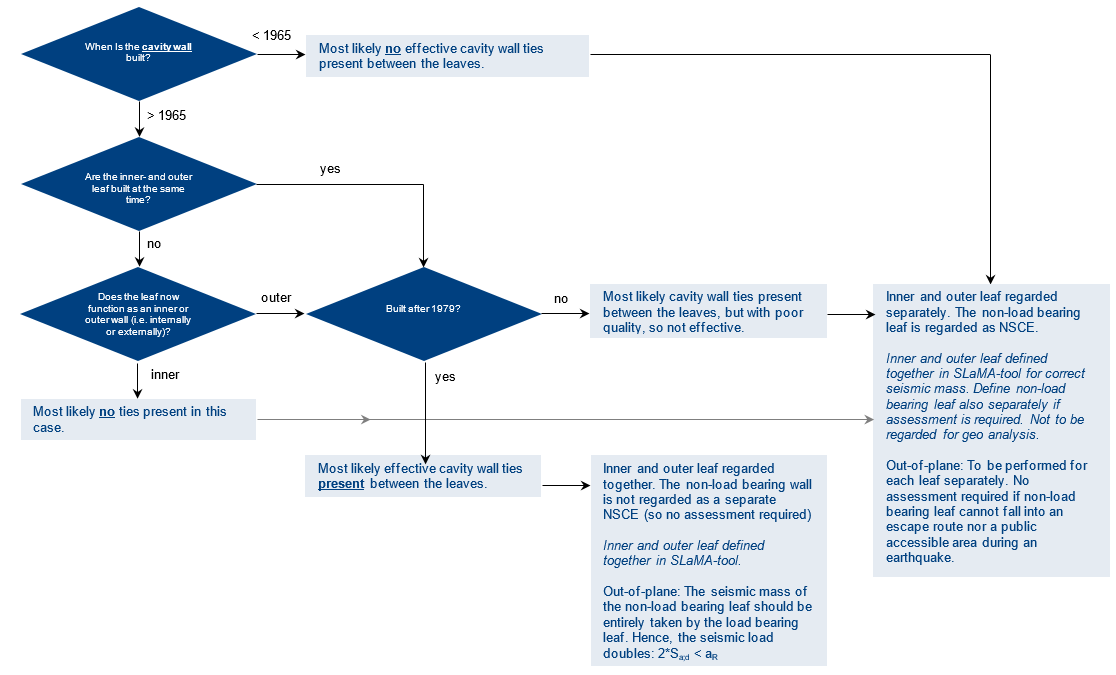
Figure 3.15 Flowchart cavity walls
3.3. Diaphragm action of floors and roofs
3.3.1. General seismic lateral force transfer
Figure 3.2 illustrates some of the terminology used for both diaphragms and wall displacements as well as seismic lateral force transfer. The example consists of four walls (WA, WB, W01 and W02) and a steel beam supported by a column. The timber floor system (spanning in x-direction) acts as a horizontal diaphragm that should be connected to the vertical lateral force-resisting elements around it. These elements can be identified as the boundaries used by the SLaMA-tool. Wall WA and WB can be identified as the vertical lateral force-resisting elements in the considered EQ direction. Wall W01 and W02 and the column in the middle are not able to take the lateral forces, so they can be schematized as hinged. The floor diaphragm transfers the (in-plane) shear forces (determined by self-weight of the floor and partial masses of W01 and W02), induced by the seismic load acting upon the diaphragm, W01 and W02, to the lateral force-resisting elements in the considered EQ direction (WA, WB).
The forces and deformations observed in the diaphragms are based on the floor fundamental period, the diaphragm’s shear stiffness, and the seismic mass acting on the diaphragm. The total seismic mass acting on the diaphragm, being the sum of the weight of the walls perpendicular to the seismic direction (half-story below), i.e. the product of the tributary height, thickness and density of the out-of-plane masonry walls, and the diaphragm self-weight plus live load ( \(\\q_k φ Ψ_2\\\) ).
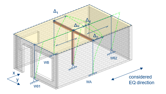
Figure 3.16 Seismic lateral force transfer.
Through timber floor and roof are considered as flexible diaphragms, they must have sufficient shear capacity to transfer the shear force induced by the seismic load acting on the diaphragm to the vertical lateral force-resisting elements. In addition, the maximum in-plane deformation at diaphragm mid-span (Δ_d) shall be less than 50% of the thickness of the perpendicular walls. Additionally, the displacement at diaphragm mid-span, i.e. the sum of the average inter-story drift Δ_w and Δ_d shall be less than 2.5% of the story height.
Important aspects:
The seismic loads in the floor will only be transferred to the walls and beams that are along the sides (boundaries);
These seismic loads will not be transferred to floors which are present ‘inside’ the floorfield. These are NSCE’s;
Only axial load contribution of the floor bearing area acting on a column contributes as seismic mass to be carried by the lateral force-resisting elements;
For each EQ direction, the mass of all walls should be present in the analysis, it is important to check this in the SLaMA-tool output (!);
The seismic mass of NSCE’s should be assigned as perpendicular load to PSSE’s (to stabilize them). Note that NSCE’s do not carry the seismic mass of PSSE’s (!).
3.3.2. Seismic lateral force distribution by floor diaphragms
The seismic lateral force distribution at (first) floor diaphragm level is explained by means of Figure 3.3.
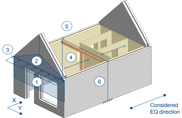
Figure 3.17 Seismic lateral force distribution floor diaphragms
Seismic mass acting on the floor diaphragm, being the weight (half-story below) of the perpendicular wall, i.e. the product of the tributary height, thickness and density of the out-of-plane masonry wall (accounting for wall penetrations). You should take half-story below, because the floor diaphragm and the foundation/ground floor support the vertically spanning wall and consequently pick up the developed horizontal reactions.
Seismic mass acting on the floor diaphragm, being the weight (1/3) of the perpendicular gable wall, i.e. the product of one third of the tributary gable area, thickness and density of the out-of-plane masonry gable wall (accounting for wall penetrations). You should take 1/3th tributary gable area, because the roof and floor diaphragm support the vertically spanning gable wall and consequently pick up the developed horizontal reactions.
Total tributary seismic mass acting on the floor diaphragm from perpendicular (out-of-plane) walls at the front. The same holds for the perpendicular walls at the back.
At the floor level, the perpendicular wall reactions, turn the load in the floor system, in the plane of the floor. The horizontal element is known as the floor diaphragm (spanning in x-direction).
The floor diaphragm resists the in-plane loads by acting as a large horizontal (deep) beam spanning between the supporting end walls that are known as the vertical lateral force-resisting elements (masonry walls parallel to the considered EQ direction).
The vertical lateral force-resisting elements, the masonry shear walls, will then resist the applied diaphragm reaction and transfer the shear load into the foundation.
Note
In case the thickness of the gable wall is not the same as the considered wall itself at ground floor level, an equivalent A_gable should be taken into account (same holds for A_gutter).
The seismic mass of the outer leaves in case of cavity walls should always be considered in the SLaMA-tool.
3.3.3. Seismic lateral force distribution roof diaphragms
The seismic lateral force distribution at roof diaphragm level is explained by means of Figure 3.18. The roof structure consists of a series of sloping rafters (in Dutch: sporen), which run perpendicular from the top of wall WA and WB to the ridge.
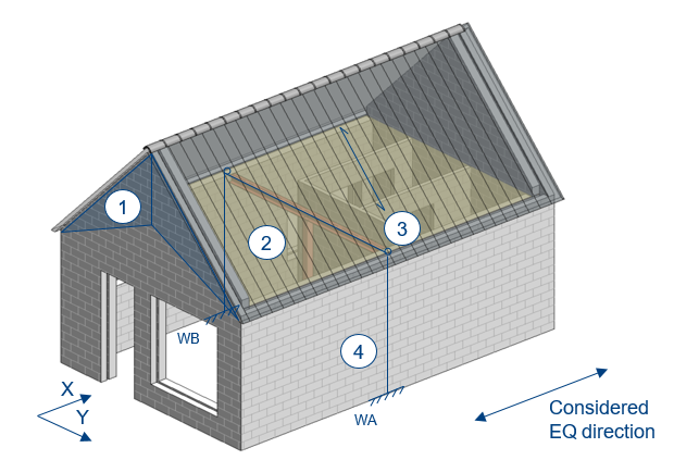
Figure 3.18 Seismic lateral force distribution roof diaphragms.
The total seismic mass acting on the roof diaphragm, being the sum of the weight of the gable walls perpendicular to the seismic direction, i.e. the product of the tributary height, thickness and density of the out-of-plane masonry gable walls and the roof diaphragm self-weight plus live load (\(\\q_k φ Ψ_2\\\)).
Seismic mass acting on the roof diaphragm, being the weight (2/3) of the perpendicular gable wall, i.e. the product of one third of the tributary gable area, thickness and density of the out-of-plane masonry gable wall (accounting for wall penetrations). You should take 2/3th tributary gable area, because the roof and floor diaphragm support the vertically spanning gable wall and consequently pick up the developed horizontal reactions.
At the roof level, the perpendicular gable wall reactions, turn the load in the roof system, in the plane of the roof. The horizontal element is known as the roof diaphragm (spanning in y-direction).
The roof diaphragm resists the in-plane loads by acting as a large horizontal (deep) beam spanning between the supporting end walls that are known as the vertical lateral force-resisting elements (masonry walls parallel to the considered EQ direction). The length of the simply supported beam is taken as 2 times the diagonal roof length in the analysis.
The vertical lateral force-resisting elements, the masonry shear walls, will then resist the applied diaphragm reaction and transfer the shear load to the foundation.
In some cases, the main roof diaphragm does not cover the entire building. There can be roof extensions along the side of the building as shown per example in Figure 3.5. Consider the roof diaphragm as a floor diaphragm with the correct stiffness and strength values.
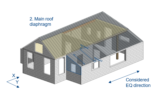
Figure 3.19 Roof extensions along the side of the building
The short side cannot be assumed strong enough if the roof spans in the long direction, parallel to the ridge, so in case of purlins.
The roof check only uses one half of the roof (because it is symmetrical) for the calculation. The check cannot be used if the short side is the weak direction, because for this direction it is not possible to only use half of the wall.
3.4. NSCE assessment
The NSCE assessment is given on Gitlab [4], see NSCE assessment.
3.4.1. Semi probabilistic analysis by means of the NLKA
The procedure of semi probabilistic analysis is described in NPR 9998:2018 4.3.6.3 and supplemented by NPR 9998:2018 Annex H for masonry structures. The capacity of an NSCE is approximated based on a presumed kinematic mechanism that is related to the geometry, location (for determining the seismic demand) and boundary conditions of the element.
It is recommended to assess the out-of-plane capacity of non-load bearing masonry outer leaves of cavity walls and non-load bearing interior masonry walls using the SLaMA-tool. Based on the results the compliance of the NSCE’s can be determined.
If the NSCE wall does not comply with a return period equal to 2475 year, you can use interpolation to prove for compliance using the correct return period (975 year).
To do so manually:
Check the capacity \(a_R\) [g] and the seismic load \(S_{ad;2475}\) [g] (corresponding to 2475 year) of the wall in case (see Table 5 Out-of-plane results for all walls of the Readout)
Check the peak ground acceleration agS for the location of the building in case for the 975 and the 2475 return period on the webtool.
To compare with the capacity of the corresponding period of the NSCE category use linear interpolation.
Use the \(S_{ad;975}\) you get after linear interpolation to compare with the capacity of the wall \(a_R\) [g] in case. If the \(S_{ad;975}\) [g] is lower than the capacity \(a_R\) [g], then the wall complies.
Example:
The capacity and the seismic load (according to a return period of 2475 year) of wall WA_ are equal to \(\\a_R=0.108 g\\\) and \(\\S_{ad;975}=0.11 g\\\) , respectively.
The corresponding seismic load follows from linear interpolation:
The local reference PGA-values for a return period equal to 475 and 975 year (time period T2) are determined based on NEN-webtool [6]. The results show that the masonry outer leaves have sufficient out-of-plane capacity.
3.5. Assessment of connections
In the assessment of connections, the goal is to check the compliance of existing connections, such as:
Floor – wall.
Roof – wall.
Roof + floor – wall.
Beam – wall.
Floor – beam.
Etc.
This section aims to give an explanation on how to deal with the connection check, by presenting a flowchart, as presented in Figure 3.6 and Figure 3.7, and giving a few cases of different possible connections. This should make the engineer more aware of the present connections in his object, and how to proceed in checking them.
3.5.1. Identifying connections
An existing connection is a connection that is most certainly present in the building without the need to verify it with existing drawings or inspections. This is the case where a floor or roof is supported by a wall or girder that is perpendicular to the span direction, i.e. (PSSE) walls which transfer both the lateral seismic load and the static vertical loads to the foundations. Existing connections are commonly not actual connections (including anchors etc.) but consist in most cases of simple wall-to-beam supports, relying on just friction in case of lateral force transfer. The SLaMA tool evaluates these frictional stresses.
As there is no wall-to-beam support for walls parallel to the span direction, there is no ‘existing connection’ that can be checked by the SLaMA-tool. In this case the shear resistance (based on friction) \(\\V_R\\\) is equal to zero, since the overburden load on these walls is zero, and consequently \(\\V_R\\\) returns zero. Since it is unknown whether there is any other type of connection there, these must be retrofitted in order to transfer lateral forces to the walls.
In addition, NSCE walls commonly require a connection at the top since they are considered to be vertically spanned for the out-of-plane behavior. As these connections are quite often absent (as the use of PUR for NSCE-wall top connections is quite common), a strengthening measure is recommended in most cases (unless an actual physical connection already has been determined during the building inspection).
3.5.2. Basic flowchart of checking connections
In this chapter a flowchart is presented, which deals with the basic cases of how to perform a connection check. A distinction is made between checking existing connections and designing new connections. Two situations are used as an example, which are shown in Figure 3.6.
Situation 1 shows a simple example of a floor supported by two walls. Parallel to the span direction of the floor another two walls are present as well. The latter two walls are not connected to the floor, because the floor beams are not resting on these walls.
Situation 2 shows an example of a floor supported by a beam (on the left) and a wall (on the right). The beam on the left is supported by two walls, which are running in the direction parallel to the floor span. The floor has a different length compared to the beam and the wall it is supported on. It cannot transfer its diaphragm loads to the bottom two walls.
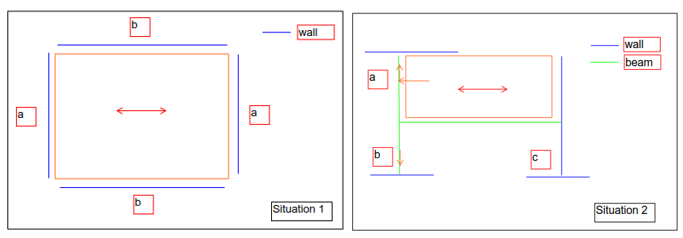
Figure 3.20 Examples.
The letters in the two situations in Figure 3.6 relate to the different outcomes, found in the flowchart. The flowchart can be seen in Figure 3.7. A stripped down version of the flowchart is presented in Figure 3.8, in order to determine when and how to check the connection between beam and floor. This connection is checked in the same way as if it was a wall. Strengthening measures are applied when the connection does not satisfy the requirements.
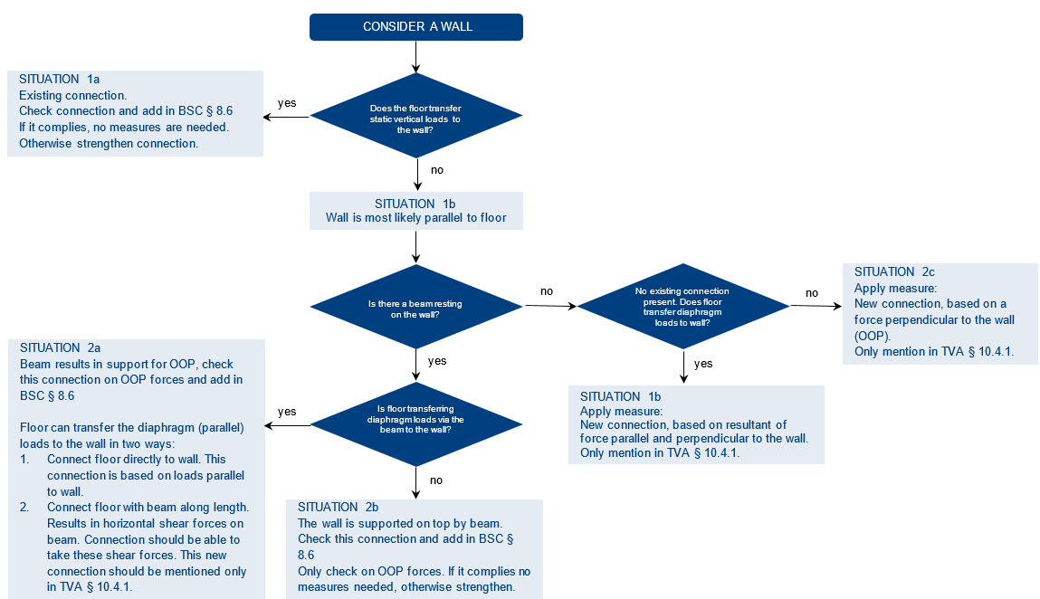
Figure 3.21 Flowchart connections.
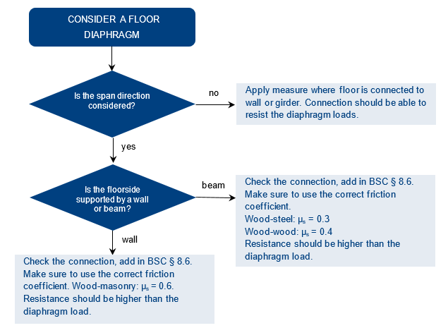
Figure 3.22 Procedure for connection check floor-beam.
Note
If a wall is only supported by a single girder on the top of the wall, the girder needs to be near the middle of the wall. For walls up to 3m we assume that the girder should be at least at a distance of half the wall height from the edge. Otherwise the girder will not be able to provide support for the whole wall. In that case, a measure should be applied. For longer walls, if the girder is not located around the middle of the wall, then a measure should be applied as well.
3.5.3. Practical approaches
In the case an existing connection does not satisfy the requirements, i.e. UC > 1.0, it is concluded that the connection does not comply. Based on observations during visual inspections of many objects it may be assumed plausible that the timber beam system supported by the walls perpendicular to the span direction are laterally enclosed by the existing masonry, as shown in Figure 3.9. The shear capacity will therefore already be sufficient in most cases, such that a retrofitting measure is not necessary in these cases.
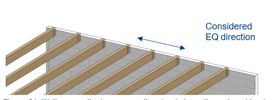
Figure 3.23 Wall perpendicular to span direction is laterally enclosed by the existing masonry.
Note
If it can be clearly seen in the EVS-2 report (inspection or pictures) that the timber beam system is not (fully) sufficiently laterally enclosed by the existing masonry, this practical approach is not applicable. However, in case this could not be determined during inspection, it is assumed that the beams are enclosed. This assumption should be clearly stated in the TVA-report and BKCL/Issuelist.
NSCE’s do not require a connection at the top for out-of-plane support if:
Their mass is less than 60 kg/m²;
The required (perpendicular) capacity F⟘ at the top of the wall is less than 0.10 kN/m. In this case the required capacity is that low that due to some cohesion in the interface (e.g. restraint displacement due to the presence of nails or screws) the required capacity will already be sufficient, such that a retrofitting measure is not necessary.
The length of the wall in case is less than or equal to 1.5 m in horizontal direction and if the wall is supported at the sides, i.e. when the masonry wall is (or can be assumed to be) interlocking with the perpendicular walls on both sides.
Roof-wall connections are often supported by wall plates (in Dutch: ‘muurplaten’) which are connected to masonry wall by means of anchors as shown in Figure 3.10. The influence of these kind of existing connection(s) should always be (qualitatively or quantitatively) taken into account. If possible (preferred) qualitative; when the connection(s) are robust, and the required capacity is limited. If necessary quantitative; by calculating the capacity of the connection(s).
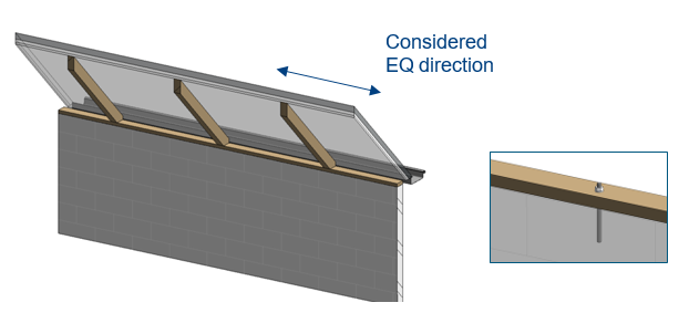
Figure 3.24 Wall perpendicular to span.
3.5.4. Multiple cases dealing with combination of floors and roof
This section deals with cases where multiple floors (with different span directions), or where a floor and roof rest on a wall.
3.5.4.1. Two floors parallel to one wall
Situations can occur where two floors, of which the spans run parallel to a wall, need to transfer their diaphragm load to this wall. An example is shown in Figure 3.25. Both floors are not directly connected to the wall because of their span. So here a connection must be made with the wall, which should be able to take the diaphragm loads from both floors combined, and the out of plane force from the wall as well. The latter is necessary because the wall does not have a support on top. With the cost-engineer it can be discussed if either one or two separate connections is preferred to make.
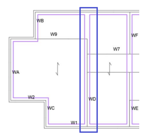
Figure 3.25 Example of wall parallel to span of two adjacent floors.
3.5.4.2. Wall connected to two floors with different spans
An example of a wall which is connected to two floors with different spans is given in Figure 3.26. Floor 1 is spanning top to bottom. This floor is resting directly on the wall. According to the flowchart, there is an existing connection between floor and wall. So, this connection needs to be checked and mentioned in BSC § 8.6. This connection should be able to take both the perpendicular load and the diaphragm load from floor 1.
Floor 2 is spanning left to right and therefore not transferring its loads directly to the wall. The floor should transfer its diaphragm loads to the wall, so a connection must be established. This can be done by making a connection between wall and floor directly. This connection must be able to take the diaphragm load from floor 2. Another option is to connect floor 1 and floor 2. This will result in the existing connection taking the loads from floor 2 as well. Per object it should be determined which option is possible and most feasible.
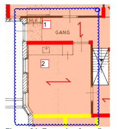
Figure 3.26 Example of two floors with different spans, connected to a wall.
3.5.5. Example of roof and floor connected to wall
This section discusses situations where a floor and a roof are connected to a wall. Two examples are discussed, where in one example the floor is supported on the wall (Figure 3.14) and in the other example it is not (Figure 3.27).
3.5.5.1. Floor not supported on wall
In Figure 3.27 an example is shown of a wall on which a roof rests, but not the floor. However, the floor should be able to transfer its loads to the wall. This means a connection needs to be made between wall and floor. Between roof and wall is an existing connection, which should be checked. It should be able to resist the out of plane force from the wall and the parallel force from the roof.
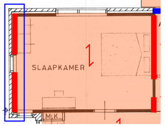
Figure 3.27 Example of roof supported on wall, while floor is not supported on the same wall.
3.5.5.2. Floor supported on wall
In Figure 3.28 an example is shown of a wall on which both a floor and roof rest. In this case there is an existing connection, which should be able to take the parallel forces from both the floor and roof, and the out of plane from the wall as well.
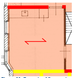
Figure 3.28 Example of floor and roof supported on the same wall.
3.6. Interpretation of results
3.7. Geotechnical assessment
Sent the results of analysis in the json-file.
To. The assigned Geo-technical engineer (project leader knows this information)
Cc. The assigned project manager.
Consult with the lead engineer if the detailed geotechnical assessment is required.