How to create piles
The workflow in VIIA for creating piles with flexbase includes 3 steps:
Step 1 is performed by the structural engineer using VIIA Pile Tool (a Graphical User Interface available in viiaPackage). Step 2 will be done by geotechnical advisor. The structural engineer will be informed when step 2 is finished, and after that he/she can create piles in mainscript (step 3).
Piles with fixed base can be directly created in mainscript using project.viia_create_piles(). No data exchange with myviia or geo calculation are involved. Example of using the function:
pile_coord = [[1.0, 0.3]]
project.viia_create_piles(coordinates=pile_coord, support_type='FixedBase', pile_group='A', cross_section='D200')
VIIA Pile Tool
VIIA Pile Tool is a Graphical User Interface available in viiaPackage, which allows users (i.e. structural engineer) to input pile data, calculate pile structural properties, send data to MYVIIA database and generate email to inform geotechnical advisor.
A template (template_pile_tool.py) for using the VIIA Pile Tool can be found in the folder of templates in viiaPackage. You can copy this template in your work folder, and change the object name accordingly for your use.
Attention
Several third-party packages are needed for the pile tool to work, including:
- PyQt5
- pywin32
Please make sure you pip installed these packages before you use this tool.
Now if you run this script, you will see the main window below popping up on your screen.
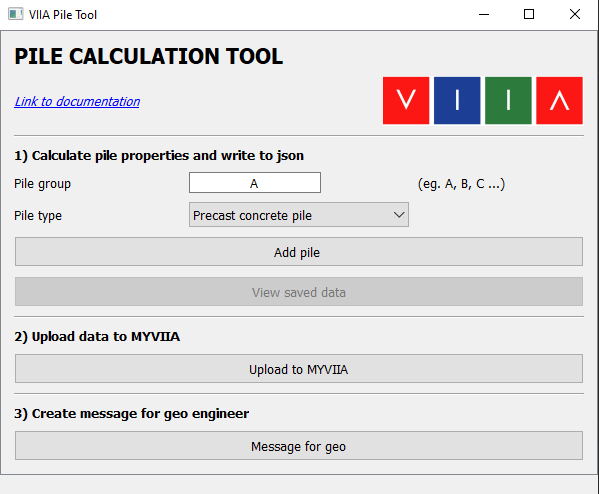
Figure 26 Main window of the VIIA pile tool.
The main window is divided into 3 parts to perform the 3 sub steps as stated in the workflow. Explanations and examples are given for each sub step below. Additionally, there is a link available at the top of the main window (‘Link to documentation’). Clicking the link will open this guide.
Add pile data
From the first part of main window, the structural engineer can add pile data and calculate pile structural properties (this was previously done using ‘paal_gegevens’ excel sheet).
First, in the ‘Pile group’ input box, input the pile group you would like to add. Following the VIIA convention, please always start with ‘A’. If you have different piles in the object, add them one by one as pile group ‘B’, ‘C’, ‘D’ etc. Then select the type of this pile group, and click ‘Add pile’ button. A pile calculation window will pop up on the screen as shown below.
Attention
Only precast concrete piles are available now. Structural calculations for other pile types are under development. Please ask the knowledgeteam.
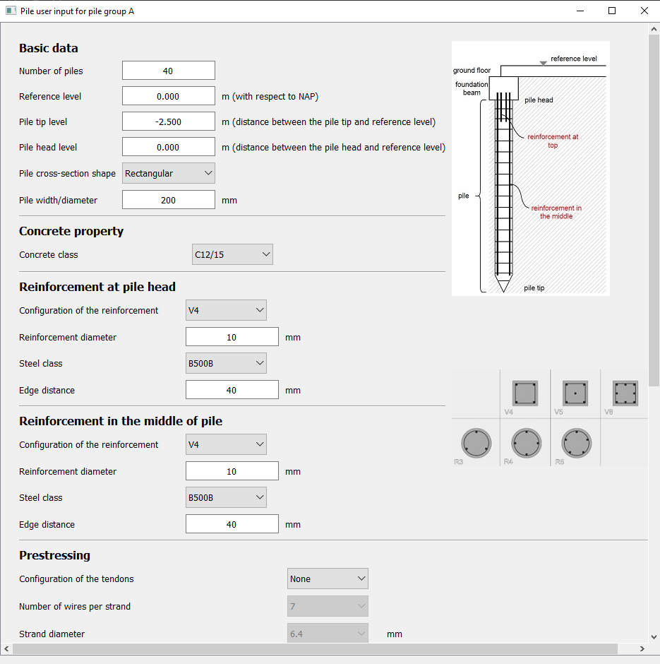
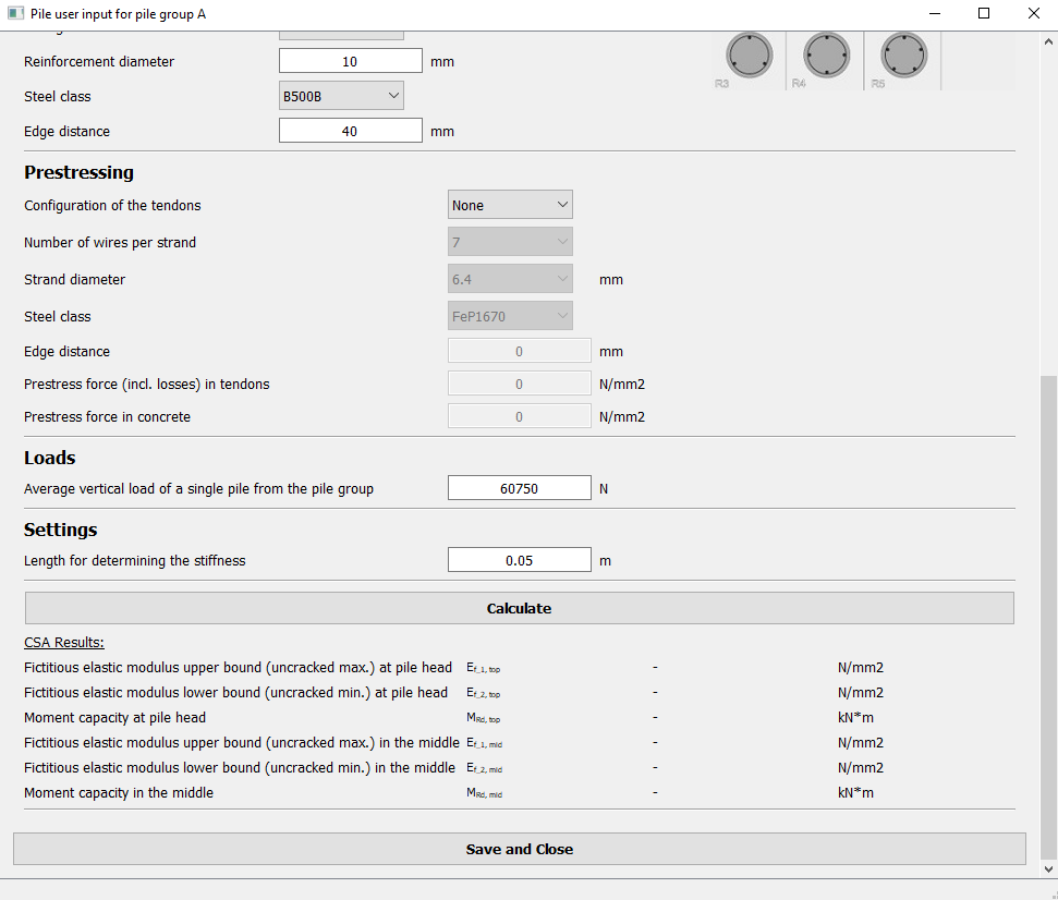
Figure 27 Input form for pile in VIIA pile tool.
In this window, you can fill in all the pile parameters (using the scroll bar on the right of the window to see all parameters). The definition of each parameter is presented at the end of this guide Pile parameters definition in MYVIIA pile tool. A pile sketch and an image for different reinforcement configurations are also present on the right side of the window.
After filling in all required parameters, click the ‘Calculate’ button. The structural properties of the pile will be calculated in the backend. A message box will show up after the calculation is finished:
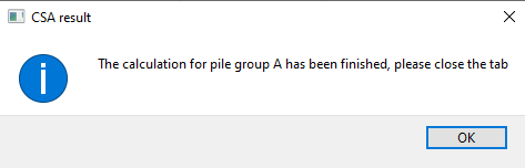
Figure 28 Message of finished calculation in the backend.
Click ‘OK’ to close the message box and the results will be displayed under the results tab in the calculation window (red box in the figure below).
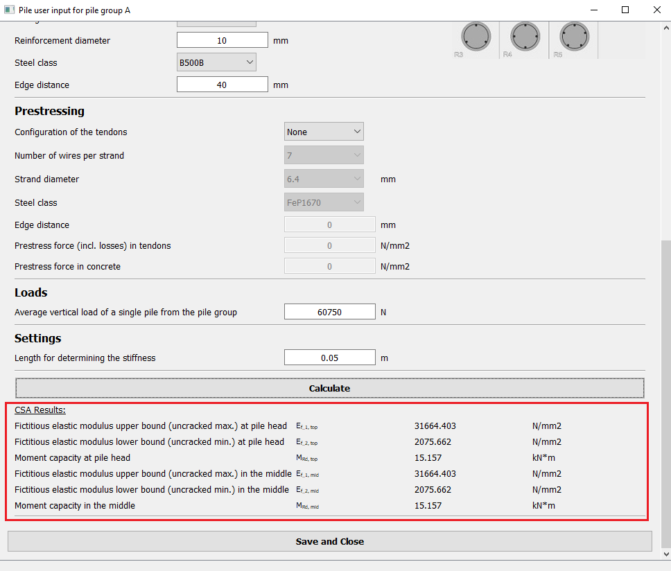
Figure 29 Additional data is now shown in the pile calculation form.
Click ‘Save and close’ button in the window. The pile data will be saved in py-memory. The pile calculation window will be closed.
Note
If there are more pile groups present in the object, please input different pile group name in the main window, then click ‘Add pile’ and repeat the procedure.
You can also view all saved data by clicking the ‘View saved data’ button on the main window. All saved data will be shown in tables in an additional window (in SI-units).
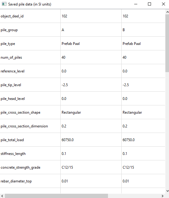
Figure 30 Saved pile data.
Note
The ‘View saved data’ function is only meant for viewing data, data cannot be edited here. If you would like to change data after saving it, please repeat the add pile procedure (input the pile group you want to edit) to overwrite data.
Upload data to MYVIIA
When all pile data are calculated and saved, you can click the ‘Upload to MYVIIA’ button on the main window to send data to MYVIIA database. Data will be uploaded per pile group.
If data for this pile group already exists in MYVIIA database, it will update the data there. A message box like figure below will show on the screen:
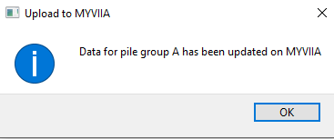
Figure 31 Message for updating data on MYVIIA.
If no data has been saved on MYVIIA for the pile group, new data will be created. A message box like figure below will show on the screen:
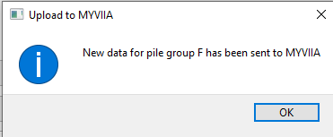
Figure 32 Message for uploading data of a new pile group on MYVIIA.
All data that is saved in MYVIIA database can be visualized on MYVIIA webtool (via ‘ENGINEERING’ tab -> ‘VIEW SAVED PILE DATA’ button).
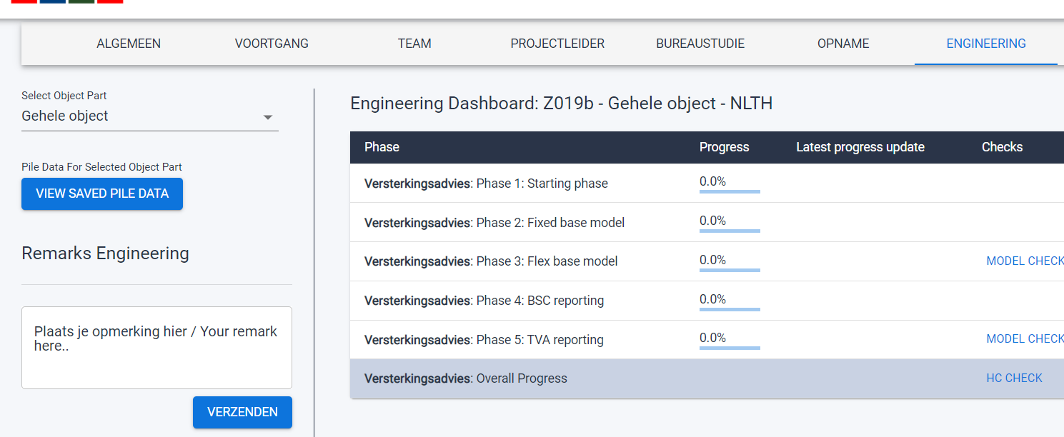
Figure 33 The ‘Voew saved pile data’ is now clickable.
Generate email to inform geotechnical advisor
After sending data to MYVIIA, you can click the ‘Send geo message’ button on the main window to generate an email to the geotechnical advisor. A message box like figure below will show on the screen:
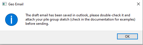
Figure 34 Message from pile tool for geotechnical advisor.
The generated email will be saved in your Outlook->Draft as a draft email. Please double check and attach your pile group sketch before sending.
A pile group sketch is needed for geotechnical advisors to see the locations of each pile group. An example is shown below:
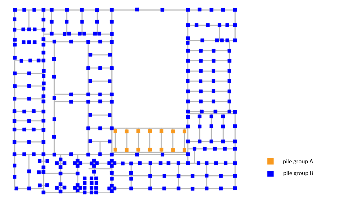
Figure 35 Example sketch of piles in different pile groups.
The sketch can be the drawing you used in appendix C1 or simply made by putting marks on the inspection drawing. It should clearly show how many pile groups are present in the object and which piles belong to which pile group.
Perform geotechnical analysis and add results on MYVIIA
Note
This step is performed by geotechnical advisor.
In step 2, geotechnical advisor performs calculations with structural inputs that are saved in MYVIIA database. Results should be entered on MYVIIA by geo engineer after the analysis. This can be done via ‘GEOTECHNIEK’ tab -> ‘VIEW/ENTER PILE DATA’ tab.
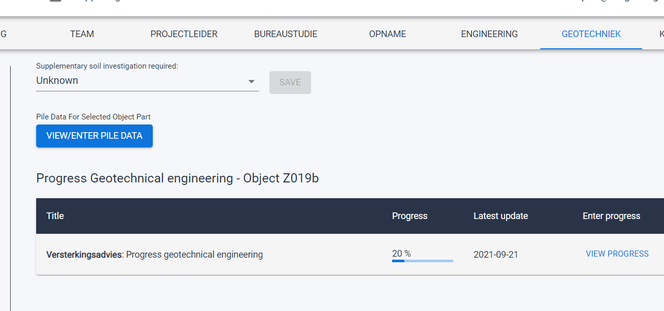
Figure 36 Dashboard on MYVIIA for geotechnical advisor for upload pile analysis.
Required geotechnical results for the structural engineer include:
- Average soil velocityin [m/s]
- Average soil densityin [kg/m3]
- Soil poisson ratio
- Soil damping ratio
- Force-elongation diagrammaximum 13 sets of data (incl. yielding point)
- Yield capacityforce at yielding point, in [N]
- Spring stiffness Zin [N/m]
- Tensile capacityin [N]
- Compressive capacityin [N]
- Effective lengthin [m]
Create piles in mainscript
The function viia_create_piles() in viiaPackage is used to create piles in the mainscript. Please
create the piles per pile-group by giving the ‘pile_group’ as an input. If ‘pile_group’ is given, the corresponding pile
data will be retrieved from MYVIIA database and be used in creating the piles in py-memory (and applied structural
software).
Example of using the function:
pile_coord = [[1.0, 0.3]]
project.viia_create_piles(coordinates=pile_coord, support_type='FlexBaseGlobal', pile_group='A')
The pile will be created with reinforcement and springs for flexbase analyses. It includes adding a user supplied subroutine with the special material model for the horizontal pile springs.
Pile parameters definition in MYVIIA pile tool
For basic data:
- Number of pilesThe total number of piles for this pile group.
- Reference levelThe level of the top surface of ground floor with respect to NAP level, in [m].
- Pile tip levelThe distance between the pile tip and reference level, in [m].
- Pile head levelThe distance between the pile head and reference level, in [m].
- Pile cross-section shapeSelect from ‘Circular’ and ‘Rectangular’.
- Pile width/diameterInput pile width if the cross-section shape is rectangular, or pile diameter if the cross-section shape iscircular, in [mm].
For concrete property:
- Concrete classConcrete strength class, select from the list.
For reinforcement at pile head and reinforcement in the middle of pile:
- Configuration of the reinforcementReinforcement layout in the pile cross-section, select from ‘V4’, ‘V5’ and ‘V8’ if the cross-section is rectangular,
or choose from ‘R3’, ‘R4’, ‘R5’ if the cross-section is circular.
- Reinforcement diameterDiameter of the reinforcement, in [mm].
- Steel classSteel strength class of the reinforcement, select from the list.
- Edge distanceThe shortest distance between the center of the reinforcement and the pile cross-section edge, in [mm].
For prestressing:
- Configuration of the tendonsPrestressing tendons layout in the pile cross-section, select from ‘V4’, ‘V5’ and ‘V8’ if the cross-section isrectangular, or choose from ‘R3’, ‘R4’, ‘R5’ if the cross-section is circular.
- Number of wires per strandSelect the number of wires per strand from ‘3’ and ‘7’.
- Strand diameterDiameter of the strand, different values can be selected depends on the number of wires per stand, in [mm].
- Steel classSteel strength class of the prestressing tendons, select from the list.
- Edge distanceThe shortest distance between the center of the prestressing tendon and the pile cross-section edge, in [mm]
- Prestress force (incl. losses) in tendonsThe working prestress force in the tendons (after deducting all the losses), in [N/mm2]
- Prestress force in concreteThe working prestress force in concrete, in [N/mm2]
For loads:
- Average vertical load on single pile from the pile groupAverage vertical load on the singe pile under seismic situation (from A1 result), in [N]
For settings:
- Length for determining the stiffness0.05 m is the default value we use in VIIA (as spring length). No changes needed for the values.
Note
If there is no corresponding reinforcement/prestressing tendons present in the pile, please select ‘None’ for reinforcement/prestressing tendon configuration. Related input boxes will be disabled in this case.