How to check for compliance NLTH
This guide contains the procedures for the checks to be performed according to chapter 9 of the Basis of Design for NLTH. In this guide the compliance checks provided in the Basis of Design are further elaborated for the assessment of non-linear time-history analysis (A12 and A15).
Concrete
Beams and Columns
To be added.
Floors
Hollow core slabs without structural top layer
The assessment of hollow core slabs without structural top layer is elaborated in section 9.2.4.4 of the Basis of Design. Hollow core slabs are checked for in-plane shear forces. The assessment criterion is:
Nxy,check = 0.1 * t
Where t is the thickness of the joint between the hollow core slabs in mm.
For a hollow core slab with a thickness of 150 mm (thickness of slab is 50 mm and thickness of joint is 130 mm), the assessment criterion is 0.1 * 130 = 13 kN/m. For the floor in the example below, it can be seen that the floor is failing.
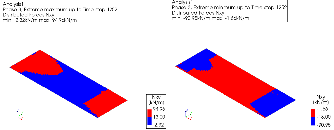
Figure 98 In-plane shear force for hollow core slabs without structural top layer
Hollow core slabs with structural top layer
The assessment of hollow core slabs with structural top layer is elaborated in section 9.2.4.5 of the Basis of Design. Hollow core slabs are checked for in-plane shear forces. The assessment criterion is:
Nxy,check = 0.5 * t
Where t is the thickness of the structural top layer in mm.
For a hollow core slab with a structural top layer of 30 mm, the assessment criterion is 0.5 * 30 = 15 kN/m. For the floor in the example below, it can be seen that the floor is failing.
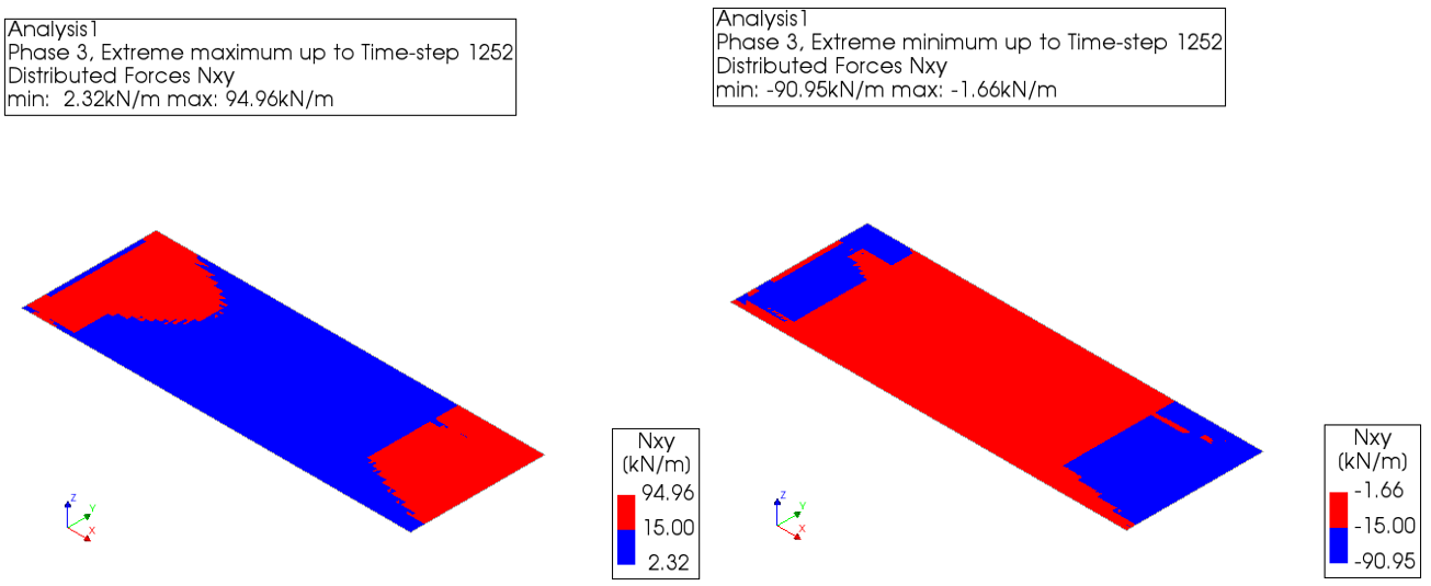
Figure 99 In-plane shear force for hollow core slabs with structural top layer
Prefabricated solid slab floors without structural top layer
The assessment of prefabricated solid slab floors without structural top layer is elaborated in section 9.2.4.6 of the Basis of Design. Prefabricated solid slab floors are checked for in-plane shear forces. The assessment criterion is:
Nxy,check = 0.1 * t
Where t is the thickness of the floor in mm.
For a prefabricated solid floor slab with a thickness of 80 mm, the assessment criterion is 0.1 * 80 = 8 kN/m. For the floor in the example below, it can be seen that the floor is failing.
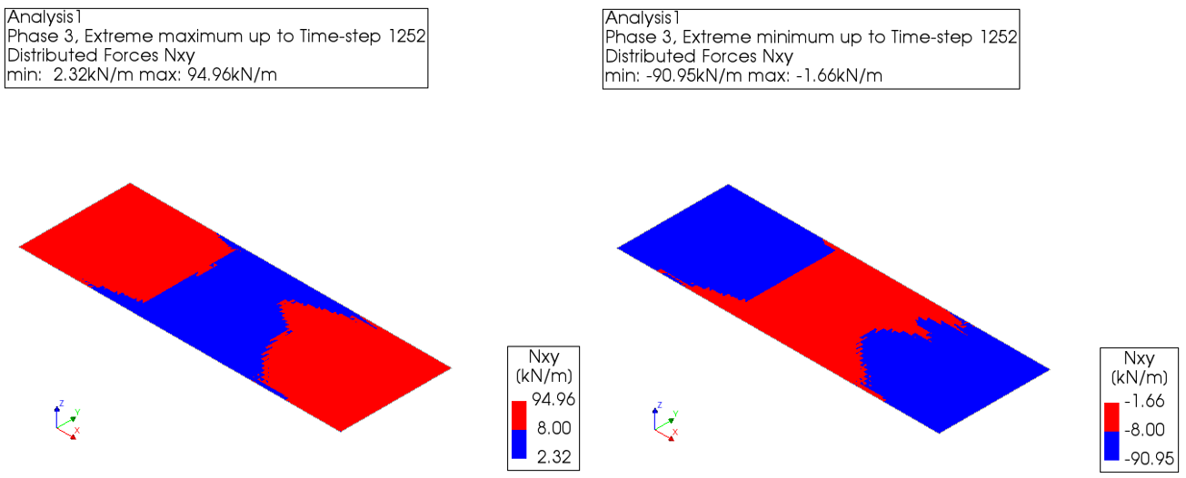
Figure 100 In-plane shear force for prefabricated solid slab floors without structural top layer.
Beam and block floors
To be added.
Steel
Based on section 9.2.5 Basis of Design NLTH 8.0, a steel element can be assessed.
Guidelines for linear steel
Check if von Mises stress exceeds the yield stress. The yield stress is the second value of item KAPSIG in Table 5-17 of the UPR.
Only the maximum equivalent stresses need to be checked.
In the following pictures, characteristic examples are shown for steel columns, steel beams and steel roofing sheets.
![Steel columns, maximum equivalent stresses Seq [N/mm2].](_images/steel_LE_1.png)
Figure 101 Steel columns, maximum equivalent stresses Seq [N/mm2].
![Steel beams, maximum equivalent stresses Seq [N/mm2].](_images/steel_LE_2.png)
Figure 102 Steel beams, maximum equivalent stresses Seq [N/mm2].
![Steel roofing sheets, maximum equivalent stresses Seq [N/mm2].](_images/steel_LE_3.png)
Figure 103 Steel roofing sheets, maximum equivalent stresses Seq [N/mm2].
Guidelines for non-linear steel
If the yield stress is exceeded follow the guidelines.
Use non-linear material properties for exceeded steel elements.
Rerun the analyses.
Use the equivalent plastic strain (DIANA: “STRAIN PLASTI GREEN VONMIS LOCATI INTPNT”)
Check whether the strain in the principal direction in the outermost fibers exceeds the fracture strain (elongation at break). In DIANA the maximal envelop for the layer can be selected. Appendix C.8 of EN 1993-1-5 proposes a limit value of 5% for the fracture strain.
Timber
Timber beam and column check
Timber is modelled with linear elastic material properties, as provided in section 5.4 of UPR. The verification of solid timber beams and columns is provided in sections 9.2.6.2 and 9.2.6.3.
For timber beams, Bending is assumed to be the governing failure mechanism for solid timber beams in the seismic situation. The stresses (DIANA: “STRESS TOTAL CAUCHY LOCAL”; Abaqus: Field Output: “S”) are requested for the envelope of all steps in the seismic analysis. For the check in the FE-model, a selection is made of all solid timber beams. It is checked whether the stresses in the outermost fibers exceed the bending strength in the direction of the grain. In DIANA you can select the maximum envelop for the layers. When solid timber beams are used for retrofitting, the strength class is assumed to be C18 in accordance with EN 338.
For timber columns, compression is assumed to be the governing failure mechanism for solid timber columns in the seismic situation. The stresses (DIANA: “STRESS TOTAL CAUCHY LOCAL”; Abaqus: Field Output: “S”) are requested for the envelope of all steps in the seismic analysis. For the check in the FE-model, a selection is made of all solid timber columns. It is checked whether the stresses in the outermost fibers exceed the compression strength in the direction of the grain. In DIANA you can select the minimum envelop for the layers. When solid timber columns are used for retrofitting, the strength class is assumed to be C18 in accordance with EN 338.
Below are the strengths of timber columns and beams for C18 and C14.
Table - Check values stresses in Timber 1D elements |
||
Timber class |
Column strength (MPa) (Compression) |
Beam strength (MPa) (Bending) |
C18 |
20.90 |
26.90 |
C14 |
16.26 |
20.92 |
Below are the examples of checking timber beams and columns via the maximum and minimum values of Sxx (normal stresses) in DIANA FEA.
![Enveloped maximum stresses [N/mm2] timber beams](_images/timber_1D_1.png)
Figure 104 Enveloped maximum stresses [N/mm2] timber beams
![Enveloped minimum stresses [N/mm2] timber columns](_images/timber_1D_2.png)
Figure 105 Enveloped minimum stresses [N/mm2] timber columns
Timber floors
Timber floors can be assessed in three different ways:
in-plane shear forces
in-plane shear strain
in-plane displacement of the floor
It is recommended to check the floors in this specific order and only continue to the next option if a floor does not pass the assessment criteria. The first two options are very straightforward and can be performed for all floors in one go by simply making use of the assessment criteria that is given in section 9.2.6.7 and 9.2.6.8. of the Basis of Design for NLTH.
Only if a timber floor does not comply on in-plane shear force and in-plane shear strain, the in-plane displacements of the floor can be checked by the structural engineer. The in-plane displacements should be checked in two directions and assessment nodes should be selected based on the behavior of the floor (cantilever vs two-side supported). This assessment has to be done for each floor separately. Examples for two floors are given in the figures below. The assessment value for this assessment is equal to the drift limit.
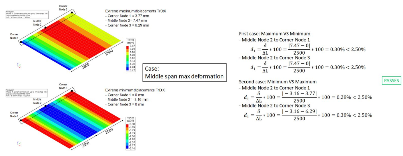
Figure 106 In-plane displacement check example 1 - regular floor checking TrDtX, midspan max deformation.
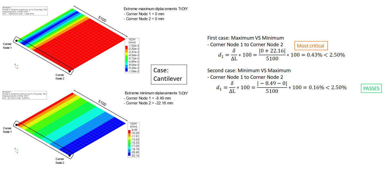
Figure 107 In-plane displacement check example 1 - regular floor checking TrDtY, cantilever
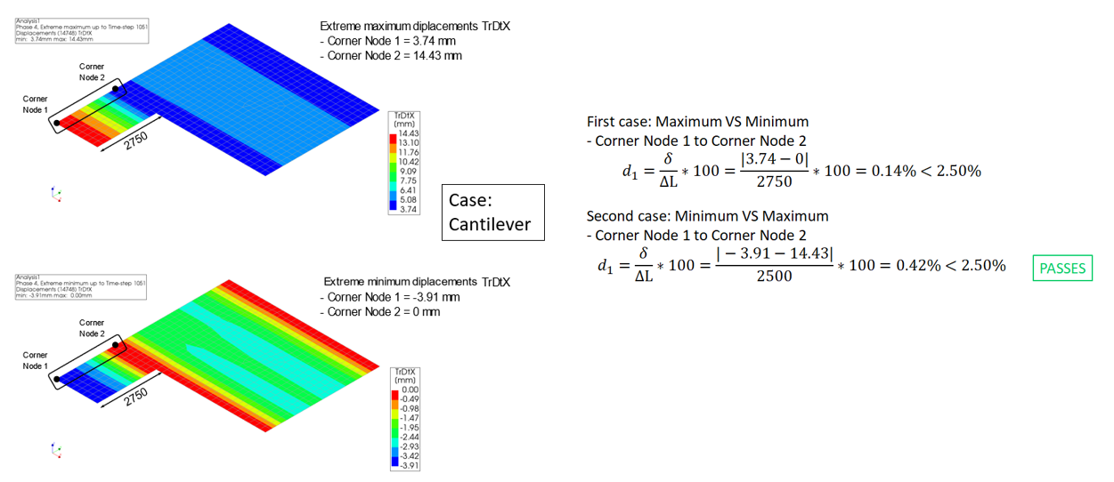
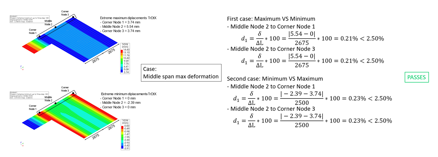
Figure 108 In-plane displacement check example 2 - irregular floor checking TrDtX [part 2/2]
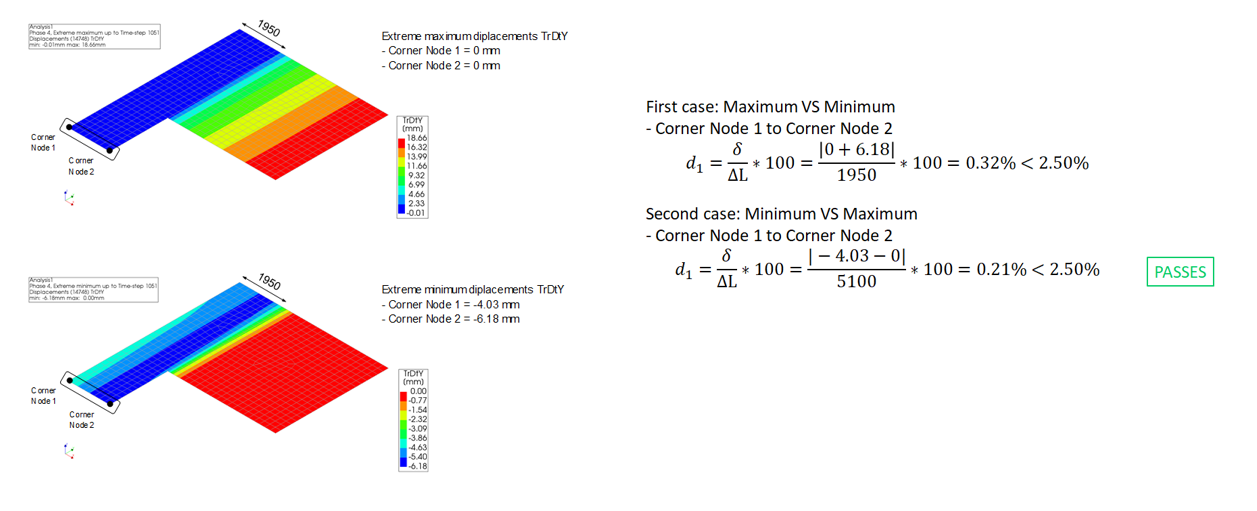
Figure 109 In-plane displacement check example 2 - irregular floor checking TrDtY [part 1/2]
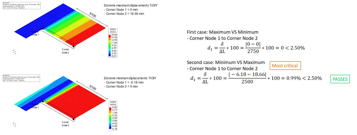
Figure 110 In-plane displacement check example 2 - irregular floor checking TrDtY [part 2/2]
Connections
Linear interfaces
Three criterion should be checked for linear interfaces:
Normal stress
In plane shear stress
Out of plane shear stress
In DIANA as is shown below, we have three directions for linear interfaces:
Normal force direction: local y (in green)
In plane shear direction: local x (in blue)
Out of plane shear direction: local z (in red)
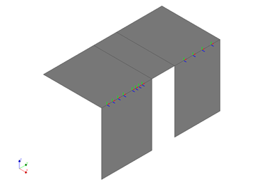
Figure 111 Axes system of connections
We take measures L2-053 and L2-054 from GMC as example:
Measure name |
Capacity values from GMC |
Capacity direction |
|---|---|---|
L2-053 |
Shear capacity 6.4 kN/m |
In plane shear direction |
Tension capacity 3.6 kN/m |
Out of plane shear direction |
|
L2-054 |
Shear capacity 6.4 kN/m |
In plane shear direction |
Tension capacity 3.6 kN/m |
Out of plane shear direction |
Warning
Always check the values on GMC website, as the capacities sometimes are updated.
First we have the normal direction check, in this case:
Only reporting the forces is sufficient, no additional checks required.
Check for tension and compression, only check peak values
An example is shown as below.
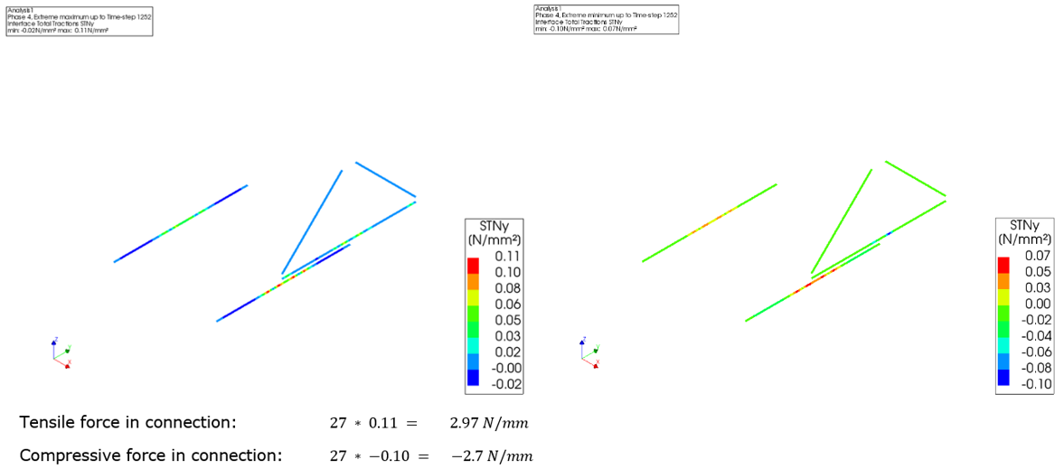
Figure 112 Linear line interface forces in normal direction
Next we can start with the shear direction checks, in this case:
Check both out-of-plane shear (local z axis) and in-plane shear (local x axis)
First check peak values (minimal and maximal)
If peak values are not satified, the average values can be delivered.
An example of in-plane shear force check is shown as below:
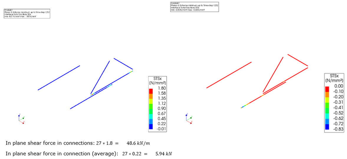
Figure 113 Linear line interface forces in-plane shear
An example of out of plane shear force check is shown as below:
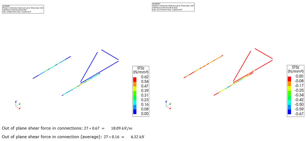
Figure 114 Linear line interface forces out-of-plane shear
Non-linear interfaces
The non-linear connections are checked based on the occurring maximum and minimum interface relative shear displacements. The compliance check is performed for the out of plane direction of the connection and the limit value is the half of the thickness of the supporting element located lower than the other.
Line connections
The line connections are applied when two elements have an edge in common. The out-of-plane local axis of the line connections is the same.
- D2.01: Support timber floor in/on masonry inner wall
Out-of-plane shear displacement DUSz
Limit value: half wall thickness
- D2.03: Support timber floor on steel profile
Out-of-plane shear displacement DUSz
Limit value: half beam thickness
(Perform the check only if the beam is at the edge contour of the floor)
- D2.07: Support timber floor on timber beam
Out-of-plane shear displacement DUSz
Limit: half beam thickness
(Perform the check only if the beam is at the edge contour of the floor)
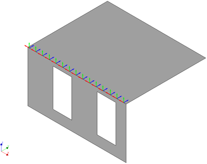
Figure 115 Out-of-plane shear displacement, local z (in blue)
In the following pictures, characteristic examples are shown for the out-of-planes shear displacements.
![Line connection D2.01, maximum (left) and minimum (right) out-of-plane shear displacements DUSz [mm]](_images/connection_NL_2.png)
Figure 116 Line connection D2.01, maximum (left) and minimum (right) out-of-plane shear displacements DUSz [mm]
![Line connection D2.03, maximum (left) and minimum (right) out-of-plane shear displacements DUSz [mm]](_images/connection_NL_3.png)
Figure 117 Line connection D2.03, maximum (left) and minimum (right) out-of-plane shear displacements DUSz [mm]
![Line connection D2.07, maximum (left) and minimum (right) out-of-plane shear displacements DUSz [mm]](_images/connection_NL_4.png)
Figure 118 Line connection D2.07, maximum (left) and minimum (right) out-of-plane shear displacements DUSz [mm]
Point connections
The point connections are applied when two elements have a node in common. The out-of-plane local axis of the point connections can vary from case to case. Look carefully in your model which local axis points in the out-of-plane direction of the wall.
- D2.01B: Support timber beam in/on masonry inner wall
Out-of-plane shear displacement DUSy or DUSz based on the local axes.
Limit value: half wall thickness
- D4.02: Support steel beam in masonry wall
Out-of-plane shear displacement DUSy or DUSz based on the local axes.
Limit value: half beam thickness
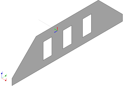
Figure 119 Out-of-plane shear displacement: local y (in green)
In the following pictures, characteristic examples are shown for all the possible the out-of-planes shear displacements.
![Point connection D2.01B, maximum (left) and minimum (right) out-of-plane shear displacements DUSy [mm]](_images/connection_NL_6.png)
Figure 120 Point connection D2.01B, maximum (left) and minimum (right) out-of-plane shear displacements DUSy [mm]
![Point connection D2.01B, maximum (left) and minimum (right) out-of-plane shear displacements DUSz [mm]](_images/connection_NL_7.png)
Figure 121 Point connection D2.01B, maximum (left) and minimum (right) out-of-plane shear displacements DUSz [mm]
![Point connection D2.07, maximum (left) and minimum (right) out-of-plane shear displacements DUSy [mm]](_images/connection_NL_8.png)
Figure 122 Point connection D2.07, maximum (left) and minimum (right) out-of-plane shear displacements DUSy [mm]
![Point connection D2.07, maximum (left) and minimum (right) out-of-plane shear displacements DUSz [mm]](_images/connection_NL_9.png)
Figure 123 Point connection D2.07, maximum (left) and minimum (right) out-of-plane shear displacements DUSz [mm]