6. Phase 5 - Final phase
After completing the fourth phase, it is possible to observe if the building requires some strengthening measures or not. In case that strengthening measures are necessary the strengthening phase of this protocol is to be performed. In case no strengthening is required only some steps of this phase are executed. The decision for strengthening is done in step 10: Step 10: Intermediate meeting LE.
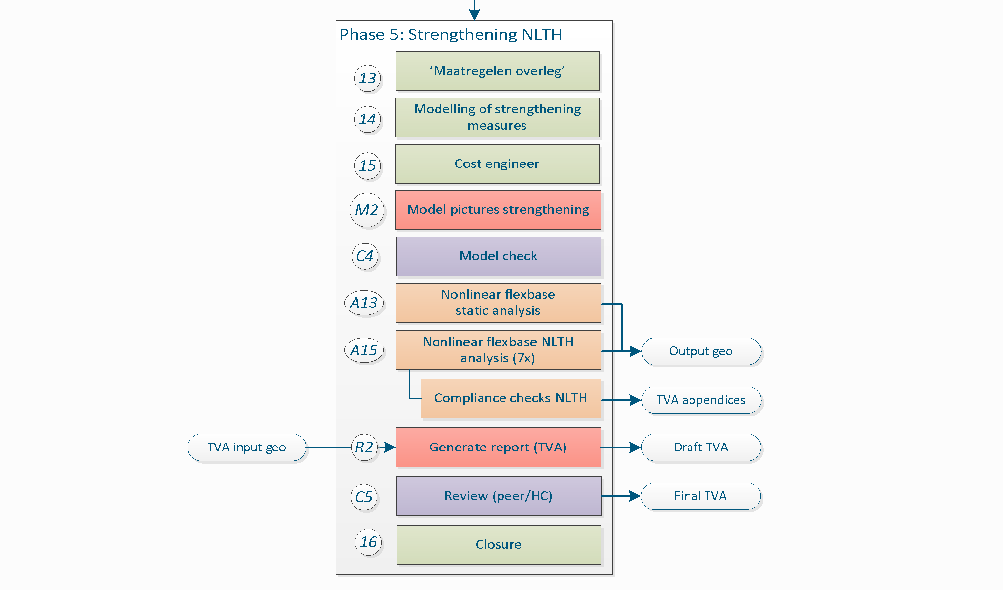
Figure 6.1 Phase 5 - Strengthening and closure.
When planning and conceptualising measures to the building, the engineer must not forget that the structural system consists not only of the model created in DIANA but must include the assessment of all building components, both structural (PSSE) and non-structural (NSCE). Refer to the how-to guide on ‘Strategies for strengthening’.
In the process to determine the required measures, a meeting with the projectleader, lead engineer and other team members is organised to discuss the measures applied in the building (NL: Maatregelenoverleg). In case of NLTH the strengthening measures are added to the FEM-model and analysed. Data needs to be sent to the cost engineer to determine the final cost of the measures applied in the building. Drawings of the applied measures need to be created.
As final step the chapter dedicated to the strengthening measures of the engineering report is prepared (TVA), reviewed by a colleague and finally reviewed by the lead engineer.
At the end of the process the object is finalised and all required data archived. It might be that VIIA continues with the object for designing for the execution the strengthening advice or a rerun of the assessment, so the data must be available and cleaned for others to use.
6.1. Step 11: Modelling of strengthening measures
Once measures have been selected it is required to add these to the model in strengthening phase. How the strengthening measures should be modelled is specified in the BoD. How to apply them is specific per measure, for which the following guide is available: How to add strengthening measures in the model.
A workshop on strengthening is available here: Workshop Advanced usage of viiaPackage (Day 1), where examples and exercises regarding strengthening are provided. The complete list of available measures can be found in the GMC catalogue.
To apply a measure, the following functions are available in the viiaPackage:
viia_l2_054()viia_l3s()
6.2. Step A13: Nonlinear static analysis
The purpose of this calculation is to test the behaviour of the structure with non-linear material properties and the connections. This analysis provides output for the geotechnical engineer. Even if the geotechnical assessment is not performed it is advised to perform this analysis. The results are compared to the A10 analyses to indicate if there is a significant increase of loads on the foundation due to the strengthening measures. In general it is assessed significant if the mass of the building is increased with more than 5%.
6.2.1. Analysis
By means of the function viia_analysis() a non-linear static calculation can be
performed:
project.viia_analysis ('A13', run=True))
6.2.2. Issues
If problems arise from the result evaluated aspects just mentioned, observe the note mentioned above.
When an analysis converges:
Add result item for stresses to the analysis and analyse again to see where peak stresses occur.
For other possibilities regarding bug fixes see section Convergence
Analysis diverges:
If divergence occurs see section Divergence.
For a better understanding of the dcf-file, read the how-to guide: How to DCF settings.
6.2.3. Results
The result handling is performed automatically when the analysis is created and directly ran in DIANA with the function
viia_results().
The following items in A10 folder should be checked:
Interface stresses (tractions) (tensile stresses and compression, area)
6.2.4. Reporting
This step does not have to be reported.
6.3. Step C3: Model check
The engineer should discuss with the technical master and lead engineer to decide if a model check for the NLTH strengthened model is necessary.
6.4. Step A15a: Non-linear flexbase NLTH analysis (1x)
This is the final analysis of the building. The model with the strengthening measures is ran again for the expected governing signal. After the analysis are finished, the engineer must check again for the compliance of the elements and overall behaviour to determine if the strengthening measures proposed are effective. If non-compliant elements are still detected, alternative or additional strengthening measures must be considered. This process can be considered as an iterative process in which the engineer applies measures and assess their effect on the structure until an appropriate outcome is reached, see Figure below.
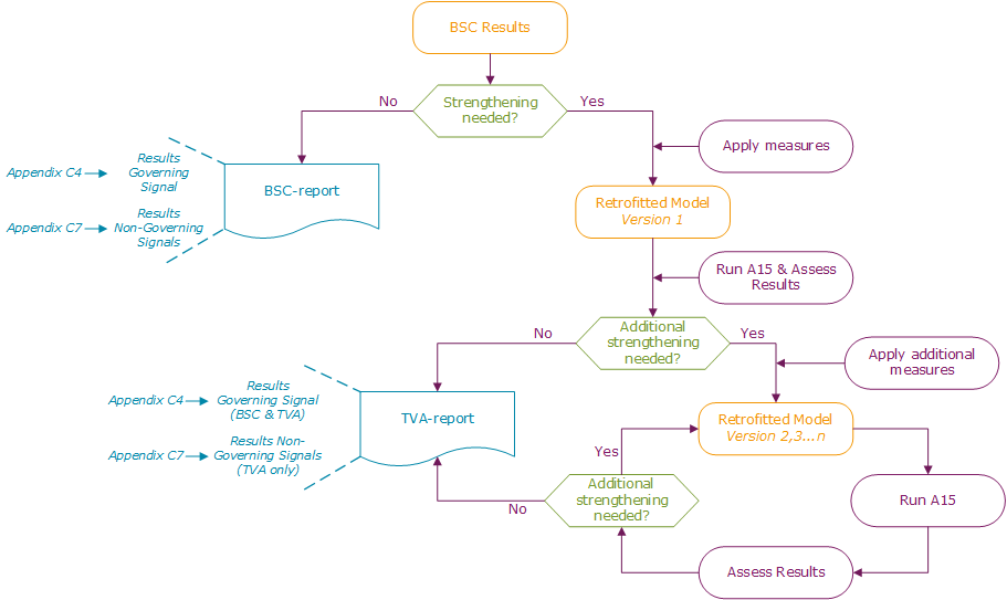
Figure 6.2 Cyclic strengthening process.
6.4.1. Analysis
Using the function viia_analysis(), a time-history can be applied with the
appropriate set of result items. Set the run argument to the default ‘False’, indicating to prepare the dcf-file and
dat-file for calculations in DIANA combox and inp-files for calculations in ABAQUS. Run the calculation preferably on
the server. The argument signals should be a list of the signals for which the analysis are created. When selecting
‘Default’, all the signals are applied in 7 separate analyses.
project.viia_analysis('A15', signals='Default')
6.4.2. Issues
If problems arise, the following steps can be taken:
When an analysis converges:
Add result item for stresses to the analysis and analyse again to see where peak stresses occur.
For other possibilities regarding bug fixes see section analyseCalculation-label.
Analysis diverges:
If divergence occurs see section analyseCalculation-label.
6.4.3. Results
As this analysis is time-consuming it is advised to run the analysis on the server in the DIANA combox. You require the resultscript to perform the result handling on the output of this analysis. Perform the steps in How to use the result-script for NLTH, after which you should assess the results described in How to check for compliance NLTH.
Check the result pictures and graphs created in the A15 folder. The following items should be checked:
Note
When applying strengthening measures that increase the mass of the building with more than 5%, the non-linear static analysis including measures should be performed. This is the A13 analysis, refer to Step A10: Nonlinear static analysis, but replace the selected analysis with ‘A13’. The geo-output should be a combination of the A13 and A15 analyis. In other cases the A15 results can be combined with A10 results for the geo-output.
When L2 measures are applied, a shear force report should be generated. This report can be generated with the
viia_results() function and setting shear_force_report to True. A report will be
generated in the ‘shear_force’ folder inside the signal folder. This report should be shared with the detail engineer.
6.4.4. Reporting
The results of the final A15 NLTH analyses will be used in the appendix C1 of the engineering report, refer to Step R3: Generate engineering report (TVA).
6.5. Step A15b: Non-linear flexbase NLTH analysis (6x)
Once the non-linear flexbase analysis was successful, the other analyses for the 6 remaining signals can be executed and checked for compliance. Refer to the previous step: Step A15a: Non-linear flexbase NLTH analysis (1x).
6.6. Step 12: Measure meeting
The goal of the strengthening measure meeting is to discuss all the possible strengthening measures that can be applied on the failing elements. The engineer should already be aware about the behaviour of the building and has to propose the measures that are deemed most suitable. During the meeting the execution team and the cost team are also present, and a discussion about the proposed measures will take place.
6.6.1. Presentation
For the meeting, a power point presentation of the building should be prepared. The presentation should have the following:
Overview of the building
Peak ground acceleration and location
Overview about the foundation (including materials and dimensions)
Ground floor: overview of all the elements: load bearing and non-load bearing (including materials and dimensions)
First floor: overview of all the elements: load bearing and non-load bearing (including materials and dimensions)
Other floors: overview of all the elements: load bearing and no-load bearing (including materials and dimensions)
In-plane strengthening measures
Overview of the walls failing in X-direction including photo of all the walls that are failing and the location/type of measure proposed by the engineer
Overview of the walls failing in Y-direction including photo of all the walls that are failing and the location/type of measure proposed by the engineer
Out-of-plane strengthening measures
Overview of the walls failing in X-direction including photo of all the walls that are failing and the location/type of measure proposed by the engineer
Overview of the walls failing in Y-direction including photo of all the walls that are failing and the location/type of measure proposed by the engineer
Overview of the strengthening measures
Present pictures that describe the location of all the elements and connections that need retrofitting
It is a good practice to include pictures to illustrate the element that is failing and to show it’s location relative to other elements of the building. The advantage of showing pictures is that cost team and strengthening team can identify obstacles, if any, and suggest alternative measure that might be easier to apply.
Proposed measure and motivation.
An example of the presentation can also be downloaded: LINK
Note
You can use the presentation of the kick-off and extend it for this meeting.
Once it’s clear which elements are failing, the structural engineer can decide on the preliminary measures for strengthening. After this, strengthening measure meeting can happen.
6.6.2. GMC (Groningen Maatregelen Catalogus)
The current available strengthening measures that can be used for the seismic retrofit of structures within the VIIA project are shown in the GMC website: https://www.maatregelencatalogus.nl/.
In the online documentation of the GMC, the measures are listed and classified as:
L1 measure: Eliminate/mitigate acute hazard
L2 measure: Coupling
L3 measure: Floors and roofs
L4 measure: Walls out-of-plane
L5 measure: Walls in-plane
L6 measure: Foundations
L7 measure: Demolition
L8 measure: System behaviour change
For each GMC measure technical information is given, as for example the capacity value, the cost and the technical execution level TGN (‘Technisch Gereedheid Niveau’). The TGN is an indicator of how much a retrofitting measure has been developed. It is a number that ranges from 1 to 7, where the higher the value, the more technically ready is the measure. A summary of the different levels of TGN is shown in the figure below.
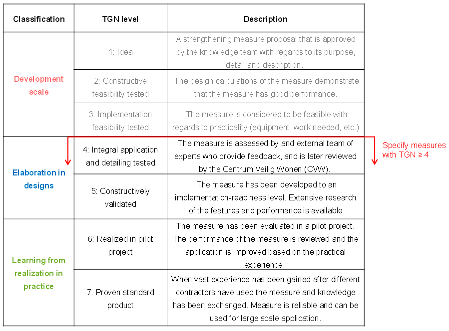
Figure 6.3 Description of TGN levels.
It is important to highlight that when recommending retrofitting measures, only measures with a TGN >= 4 should be specified.
Before selecting a measure the following aspects should be considered:
Structural capacity to ensure the measure has the required strength that the current element lacks.
Cost of the measure. When several suitable options are available, choose the one that is most economic
Technical Execution Level (TGN, in Dutch ‘Technisch Gereedheids Niveau’). Wherever possible, choose a measure with TGN >= 4.
Impact on Space. Wherever possible, select a measure that has minimum impact on available space in the room.
Impact on Aesthetics. Wherever possible, select a measure that has lowest impact on the aesthetics of the room.
Selecting a measure should be done taking into account all the points explained in the previous section 6.1.1 and also consideration related to the cost of the measure, the difficulty in implementation and last but not least, the aesthetic and spatial impact of it (related also to approval from the client).
Note
It is important to have the access to the GMC. In case you don’t have it please contact Thomas Dam (Thomas.Dam@haskoning.com).
During the meeting, proposed measures and motivation behind selection is discussed. The projectleader chairs this meeting and is joined by the lead engineer and the cost engineer.
After the measure meeting the strengthening measures need to be finalised and their corresponding motivation updated. The motivation consists of the reason why a specific measure has been decided. It is really important; the engineer has to be careful and precise and include the criteria involved in the selection of the measure (refer to the aspects of consideration when selecting a measure). Pictures should be included where the location of the measures is clearly shown. The text of the motivation will be later on added in the TVA report.
After the meeting and when measures are final, it is important to send these to the cost engineer along with some other key information about the building. Refer to section Step15-label. The reason why a specific measure has been decided is really important; the engineer has to be careful and precise with the motivation of the measure. The text of the motivation will be later on added in the TVA report.
6.6.3. Drawings Strengthened Situation
The client requires to provide drawings of the strengthening advice. These drawings are also used to communicate to the owners. This means that the drawings should be clear on where and how the measures are applied, but full detail and detailed dimensions are not required.
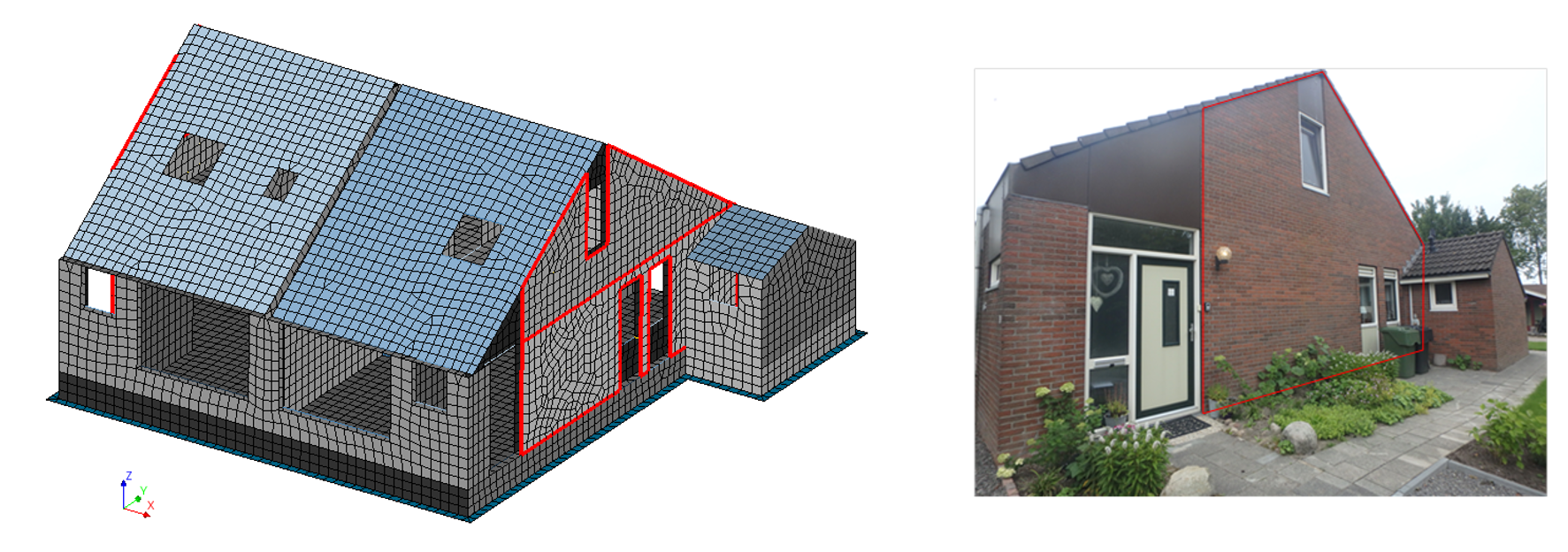
Figure 6.4 Image or picture to indicate the location of the suggested strengthening measure.
After the measures meeting you need to provide the necessary information for the draftsman. To create proper drawings you need to provide the complete measure-code from GMC (e.g. L4-D-1 and a picture of the measure (sketched). If the location of the picture is not clear also a (plan)view of the location of the measure could be provided. This should be done for all applied measures. This information is placed in a folder on box. You do not need to inform the draftsman that the data is available. If the data on box is insufficient the draftsman will contact you.
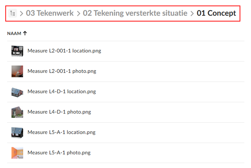
Figure 6.5 Location on box to store the information for the draftsman.
When the draftsman finishes the overview strengthening drawing he will tag you on box. You need to check specifically the applied measures. If the lead engineer wants to check the drawings too, you should tag him/her yourself. It is not necessary to check the existing situation on the drawing. The drawing should provide a recognisable image of the object, and only in case of real big differences, that should be noted. The inspector is responsible for the check on the existing drawing before applying the measures.
A checklist is available for the review, which should be used as a guideline:
Measures correctly represented
Measures in the (GMC) prescribed colours
Legend with applied measure-types
Legend describing structural elements (NL: ‘Renvooi’)
Title-block completely and correctly filled
Existing situation sufficiently recognisable
Note that the pictures have high priority, please respond within two working days. After two days the projectleader will be tagged. Note that the overview drawing with measures will not be part of the TVA report.
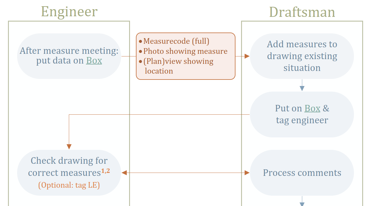
Figure 6.6 Workflow phase 1 for overview drawing strengthened situation.
After approval of the overview drawing the draftsman will create the measure specific drawings. You will be tagged by the draftsman when these are ready. And again respond within two working days for efficiency. The instructions on the review of the overview drawing are also applicable on these drawings. It is the responsibility of the structural engineer to tag the lead engineer if he requests to be involved in the check procedure.
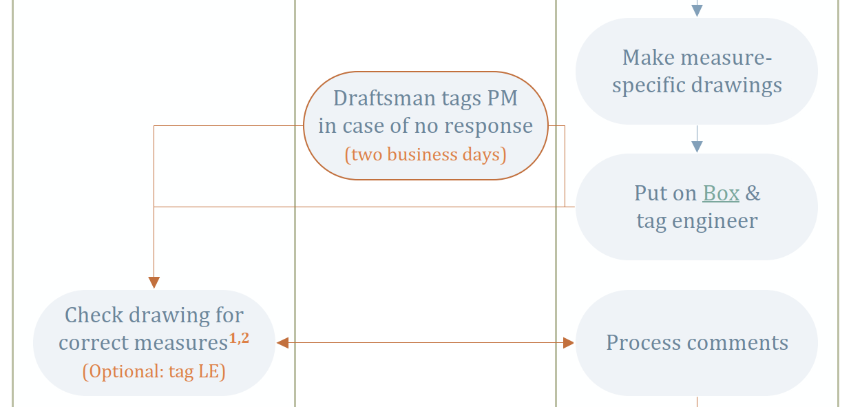
Figure 6.7 Workflow phase 2 for the measure specific drawings of the strengthened situation.
6.7. Step 13: Cost engineer
Once that the measures have been selected and approved by the lead engineer, data needs to be sent to the cost engineer. The cost engineer requires an overview of the applied measures, including dimensions and some key figures that the client requests. To calculate cost key figures, function is available in viiaPackage.
6.7.1. Collect cost key figures
Note
For the PraktijkAanpak tender specifications the cost key figures are not required when the object is not strengthened.
Collect the walls of the facade in a list. In case of cavity walls with inner- and outer leaves, only the inner ones are collected). A function is developed to assist in creating this list, but the list should be checked, and manually changed if the function did not perform correctly.
facades = project.viia_get_facades()
If the list is not correct, update the list manually:
wall = project.viia_get('N0-WANDEN-MW-KZS>1960-150-1', collection='walls')
facades.append(wall)
Now the data can be sent to MYVIIA and an excel sheet can be creates with the requested key figures. The figures are based on the fem-model in py-memory. A function is developed for this:
project.viia_create_cost_key_figures(facade_list=facades)
This function computes the requested areas for the different key figures (floor areas etc.) and does this based on the properties in the FEM-model. After this the function uploads the data to MYVIIA. In MYVIIA you can view the figures that are uploaded, you should check if they are correct.
In some cases certain elements are not modelled. For example the ground floor may not be included in the model. In that case you should specify the areas of these elements and inform cost engineer. He can update the figures in MYVIIA.
The figure below explains the meaning of a few of the key cost quantities quantities like, BVO and BBO.
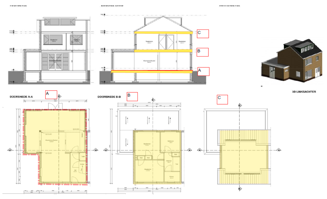
Figure 6.8 Cost key figure quantities explanation.
6.7.2. Send final selection of strengthening measures
When the strengthening measures have been finalised and discussed in the measure meeting, the cost engineer requires dimensions of the applied measures. The following items should be provided to cost engineer:
Type of strengthening measure and area/length of the measure needed (depending on whether measure is applied on an area or along a line)
Location where the strengthening measure is needed. Attach Maatregelenoverleg presentation.
The selections and quantities for the strengthening measures are to be filled in MYVIIA. The button view/enter object strengthening measures can be used to input this data. The data in MYVIIA is then used by the cost engineer and is also part of the required data for the engineering database (see the closure step).
Select your measure, and use the specific tag that was discussed in the measurement meeting. Add the quantity (could be per meter, per square meter or number of applications). If your measure is not in the list (the list complies to the list of meaures available in the cost template), you need to specify ‘Lx not in GMC-list’ at the bottom of the list. Do select the correct type of meaure (L2, L3 etc). Only use this option if you specifically discussed that with the cost engineer.
6.8. Step R3: Generate engineering report (TVA)
As a final step the engineering report or TVA needs to be finalised. Refer to
Overview and Instruction of the
Reporting guide for information on this step of the reporting process. The
viia_create_report() function has been developed to automatically get the right
templates and insert some object-specific information. Consult
Automated Reporting for information on how to use this function. For the
reporting part of the process a separate script has been developed, the reportscript for which a template is created
at the start of the object.
6.8.1. Drawings in the report
The drawings of the existing situation will be added to the appendix A1. With the report generation tool the engineer will have a prefilled cover page with the general information. The should add it to the correct box-folder, the editors will add the drawings of the existing situation.
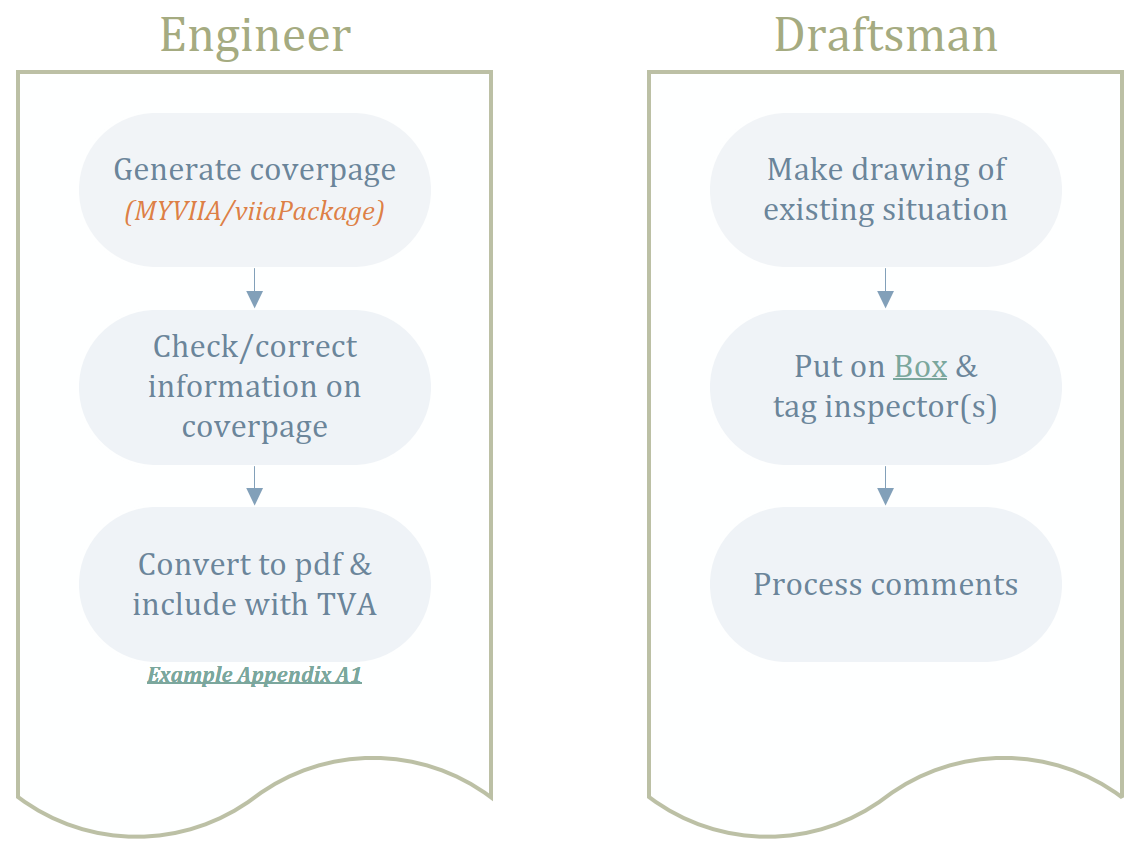
Figure 6.9 Workflow reporting existing situation drawings.
When the drawings are approved you can add the measure specific drawings to the report. These should be added to appendix A2 and C1 along with the pictures of the measures created earlier. Also this cover page can and should be generated with the functionality in viiaPackage, which also provides the preset information on the cover page.
When the drawings are added make sure that the dimensions for the measures are present. Once the drawings are added to the appendices, pdf-files are created from those. These are added on box and the lead engineer should be tagged. The draftsman is not involved in the TVA reporting phase.
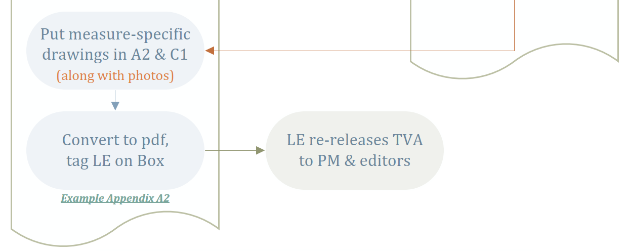
Figure 6.10 Workflow reporting measure specific drawings.
6.8.2. Background information
Here you can find additional information for the procedures to deliver the drawings of the object:
The protocol for the draftsman can be found here and provides insights on the quality of the drawings and the quality procedure. MOVED TO SHAREPOINT
Full flow chart of the procedures between engineer and draftsman. LINK Workflow
Recording of the VIIA instruction of way-of-working drawings 21st February 2023. MOVED TO SHAREPOINT
6.9. Step C4: Review (peer/HC)
When the report is finished the review needs to be performed, before the document is provided to the editors.
6.9.1. Peer review
The draft of the engineering report (including appendices) is reviewed by a colleague. Refer to Peer review instructions.
6.9.2. Lead engineer review
When the lead engineer review of all documents is finished, the lead engineer needs to record this in MYVIIA. The lead engineer is responsible for filling out the QCsheet (see QC-sheet), if this is required for the tender specification.
After completion of the reporting (also consult Completion), peer review, and lead engineer review, the lead engineer shall report finalisation of the engineering-process to the project leader, either through sending an email or a box-message. The lead engineer will verify the report documents first before sending them to the project leader and the editors.
Note
The lead engineer should provide approval in MYVIIA tool, which is part of the release process of the deliverable by project support.
E-mail or Box-message shall be directed to:
To: Project leader and editor (currently Anastasija).
CC: Structural engineer.
6.9.3. Final deliverables
Refer to here for a list of deliverables that are required for delivering to the client.
6.10. Step 14: Closure
Final closure of the project consists of the following tasks:
Server cleanup: No data is allowed to remain on the server. Any remaining data will be removed after 3 months without notice.
Box archiving: All scripts, analysis and other used files (dcf-, out-, dpf-, dat-files are saved to box). Result files (large dnb-files) should not be saved to the box folder, but the files to reproduce them should! Storing the viiaPackage is not required (all old versions are stored), when you save the log-files, the used versions are retrievable.
Add data of object to the engineering database on MYVIIA (this data is required for the reference approach for example).
Make sure the project progress on MYVIIA is 100% and reviews are checked and approved.
6.10.1. Archiving files on box
The files used to create the model and the files created (without the result files) should be saved to the following box-folder:
Objectname > 01 Projectfases > 01 Opname & Beoordeling > 04 Versterkingsadvies > 01 Technisch Versterkingsadvies > 03 NLTH > 02 Definitief > Workfolder
6.10.2. Engineering database
For all finished objects we collect some key figures so that we can perform database studies on the assessments we perform in VIIA. It is important to correctly fill in the database.
The engineering database can be filled on MYVIIA and requires general input and the selected strengthening measures. Only after saving this data, select that you completed the task in the progress sheet (you get a warning that it will be locked!)
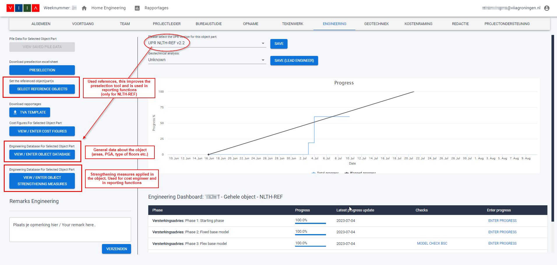
Figure 6.11 Input for engineering database on MYVIIA.
A tool is available to collect the required data directly from the workfolder, MYVIIA and from the model. The tool will calculate values and the user can accept those or correct them before sending to MYVIIA. The tool can be used together with the input on MYVIIA directly and has been developed to assist the engineer to collect the data more easily.
Refer to: How to use the engineering database tool.