In this chapter, general guidelines are listed that are derived from past experiences and engineering judgment. Based on
the specific behaviour, the different observations are listed. Also, examples from previous reference buildings are
given in this chapter.
From previous NLTH analyses, it can be said that most (smaller) buildings do not show in-plane failure. Nevertheless,
the in-plane behaviour of the structure still needs to be assessed. This section deals with the different aspects that
need to be considered when assessing the in-plane behaviour of the building and the critical element(s) using the
REF-NLTH method.
Initially, it is recommended to assess the in-plane behaviour by reference building(s) from the NLTH database.
Suitable reference object(s) for the in-plane behaviour of the selected critical element(s) can be selected based on the
same criteria used in the selection of the critical element regarding stiffness, acting mass. Other parameters
influencing the seismic load, as the Design Peak Ground Acceleration (PGA) must also be considered.
When looking for reference objects, the following characteristics are relevant in the selection process:
Similar design PGA, ag;d
A reference building(s) with ag;d up to 20% lower can be used, only if the in-plane check shows 80% or more capacity
Same/equivalent type of diaphragm
Stiffness:
Similar wall thickness, wall material, wall dimensions, presence of openings, combination of wide and slender piers,
expected stiff or ductile behaviour
Mass:
Similar or higher tributary area from first floor and roof (flexible diaphragms), similar amount of perpendicular
walls
Similar or smaller value of overburden load
The same criteria can be followed in case of assessing the global in-plane behaviour (only if needed).
For buildings similar to the ‘Krimpje’ typology, please refer to Annex A of the UPR document [RA1]. In Annex A, an
overview of the behaviour and results for each component is given.
The core of the REF-NLTH method is the use of NLTH results for the analysis and comparison of the behaviour of the
building. Therefore, only in case a similar object is not available, then a SLaMA calculation can be performed if
necessary and useful. The SLaMA method can be overly conservative in some cases, so it should be used with care.
From previous NLTH analyses, it can be said that most (smaller) buildings do not show global in-plane failure. In-plan
failure is only observed in buildings with high pga (>0.18g) and very few/small walls in one direction. An example is
given below.
Following examples of the buildings assessed with the Reference Approach are given.
Only a short summary of the building and the used reference buildings is shown. For a detailed description please refer
to the TVA of the specific building.
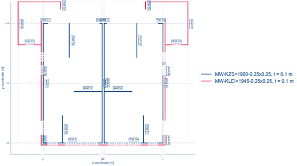
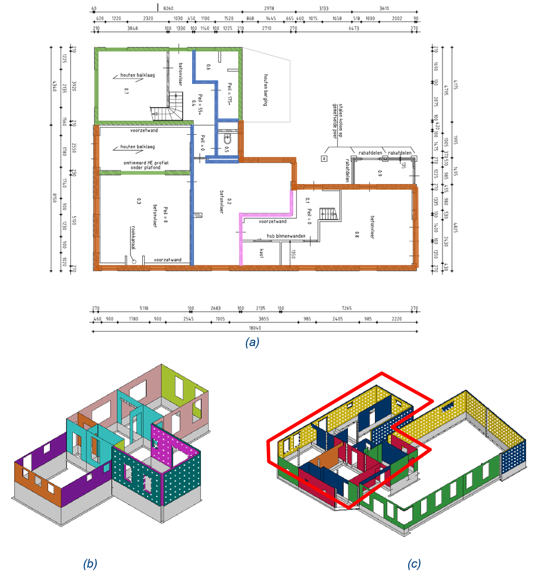
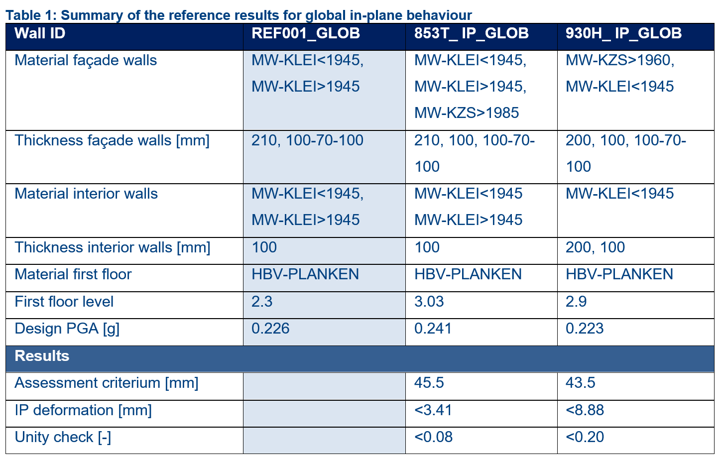
Figure 9.2 shows which reference buildings have been used for the global in-plane behaviour of REF001. Table 9.1 shows
the comparison of the results between REF001 and the reference buildings.
Figure 9.1 Global In-plane behaviour, (a) REF001, (b) 853T, (c) 930H only the part highlighted in red colour.
Figure 9.2 Summary of the reference results for global in-plane behaviour.
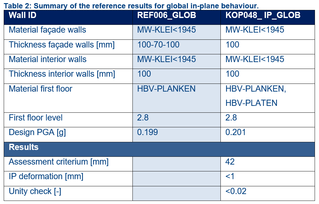
Figure 9.3 shows which reference buildings have been used for the global in-plane behaviour of REF006. Table 2 shows the
comparison of the results between REF006 and the reference building. This building is similar to the ‘Krimpje’ building;
a reference to Annex A of the UPR document [RA1] can be made.
Figure 9.3 Global In-plane behaviour, (a) REF006, (b) KOP048.
Figure 9.4 Summary table of the reference results for global in-plane behaviour.
Figure 9.4 shows which wall (highlighted in red) has been considered critical for in-plane behaviour in REF001. It has
been selected as a critical element because of the presence of a large opening and the relatively large distance to its
nearest parallel walls. It is expected that the wall has enough deformation capacity to meet the in-plane deformation
requirements.
The expectation for the above-mentioned wall has been checked with the SLaMA approach and it has been concluded that no
in-plane failure for the wall is expected. For the details please refer to the TVA report of REF001.
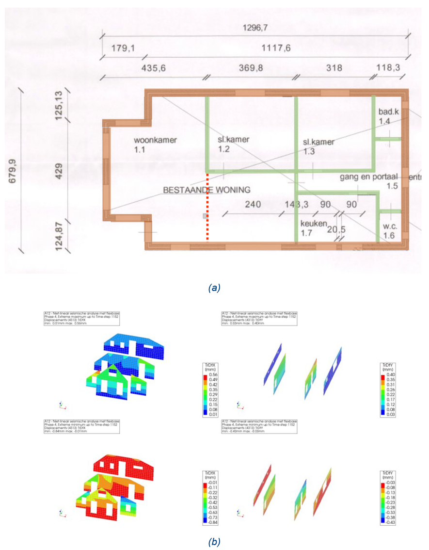
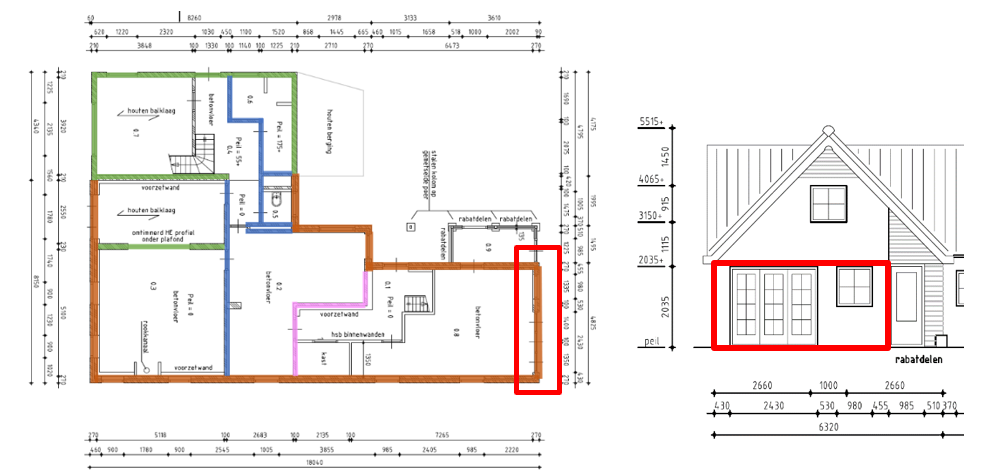
Figure 9.5 shows which wall (highlighted in red) has been considered critical for in-plane behaviour in REF006. It has
been selected as a critical element because of the two openings, the lower overburden load since the floor is spanning
parallel to it and its relatively large distance to the two perpendicular walls. It is expected that the wall has enough
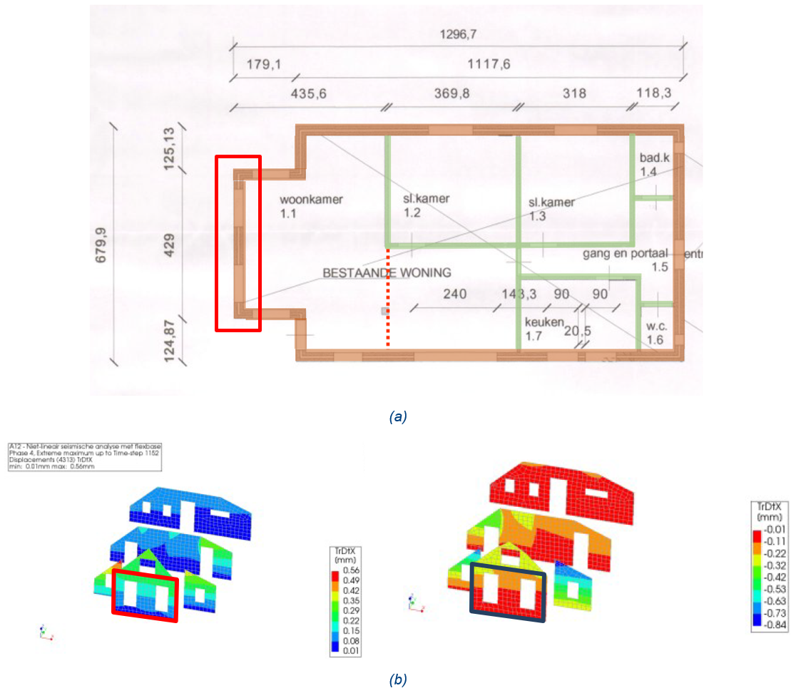
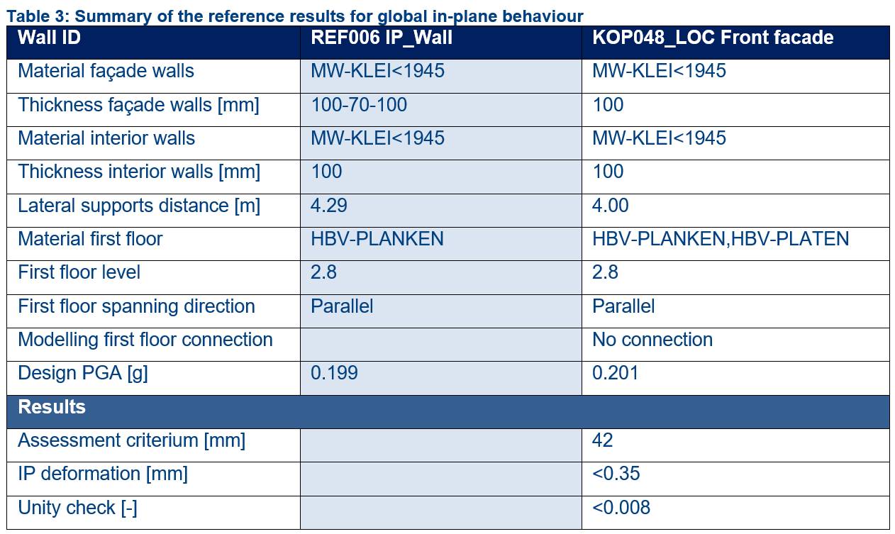
deformation capacity to meet the in-plane deformation requirements. Table 9.3 shows the comparison of the results
between REF006 and the reference buildings.
Figure 9.6 Global In-plane behaviour, (a) REF006, (b) KOP048.
Figure 9.7 Summary table of the reference results for global in-plane behaviour.
9.2.1.1. Out-of-plane behaviour according to Annex H of the NPR 2020
The seismic check for the out-of-plane capacity of the building components can be performed following one of the five
validation methods listed in section 2.4. Following a more detailed description of Annex H of NPR 2020 [RA3] is given.
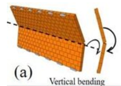
The out-of-plane behaviour of unreinforced masonry walls can be checked according to the NPR 2020 [RA3] Annex H for one
way bending (vertical bending) and if required for the 2-way bending which incorporates both bending in the vertical and
horizontal directions (horizontal from the side supports of walls).
It is suggested also to read the document ‘VIIA_QE_R2037_Meta-analyses of NLKA.pdf’ February 16 2022 available at this
link https://royalhaskoningdhv.app.box.com/file/807351477854 (VIIA Algemeen>16 Uitgangspunten (Nog in te dienen bij
CVW))
Vertical bending and behaviour of walls 200mm thick
The vertical one-way bending failure is connected to the tension strength of joints.
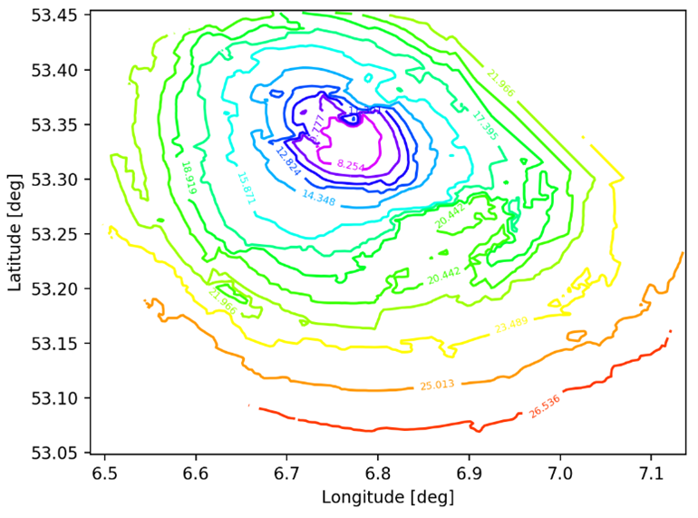
An example of one-way bending is shown in Figure 9.6. Based on the graph depicted in Figure 9.7 it can be concluded
that all unreinforced masonry walls having a thickness of 200 mm are passing the one-way bending check up to a height
of 8 meters. The assumptions used to create the image of Figure 9.6 are conservative which allows to conclude that in
general all 200 mm walls in the Groningen region have no problem linked to the T2 seismic scenario and hence no
measures are required.
Figure 9.9 Critical unreinforced masonry wall height curves for the region of Groningen for a 200 mm thickness masonry and
one-story structure. Boundary conditions top=2 and bottom=4. Seismic demand spectrum for T2 intensity. The effective
period of the structure assumed as Teff=0,4 s and the most critical overburden load has been used for the
calculation. The values of the curves are in meters.
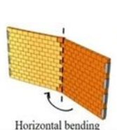
Horizontal bending
The horizontal one-way bending failure is connected to the fact that cracks can occur throw the bricks, or they can
follow the joint pattern even if through the joint pattern there is higher strength and larger friction.
For walls with a thickness of 100 mm that are supported on three sides and have a length of 1.5 m or less, it is assumed
that the out-of-plane behaviour complies. Therefore, these walls need no further OOP assessment.
In addition, such walls are also believed to comply with out-of-plane deformation requirements in cases where they are
connected to an outer leaf with functioning wall ties and are believed to carry the added mass of the outer leaf (mostly
100mm thick masonry clay leaf).
Freestanding walls that have no supports on three sides act as cantilevers and don’t have sufficient deformation
capacity for horizontal loads. Therefore, freestanding walls need to be retrofitted.
9.2.1.4. Two-way bending walls with perpendicular support
Two-way bending walls up to a length of 5m which present perpendicular walls as support for the OOP displacement are
considered to comply based on engineering judgment.
In addition, such walls are also believed to comply with out-of-plane deformation requirements in cases where they are
connected to an outer leaf with functioning wall ties and are believed to carry the added mass of the outer leaf (mostly
100mm thick masonry clay leaf).
Following examples of the buildings assessed with the Reference Approach are given.
Only a short summary of the building and the used reference buildings is shown. For a detailed description please refer
to the TVA of the specific building.
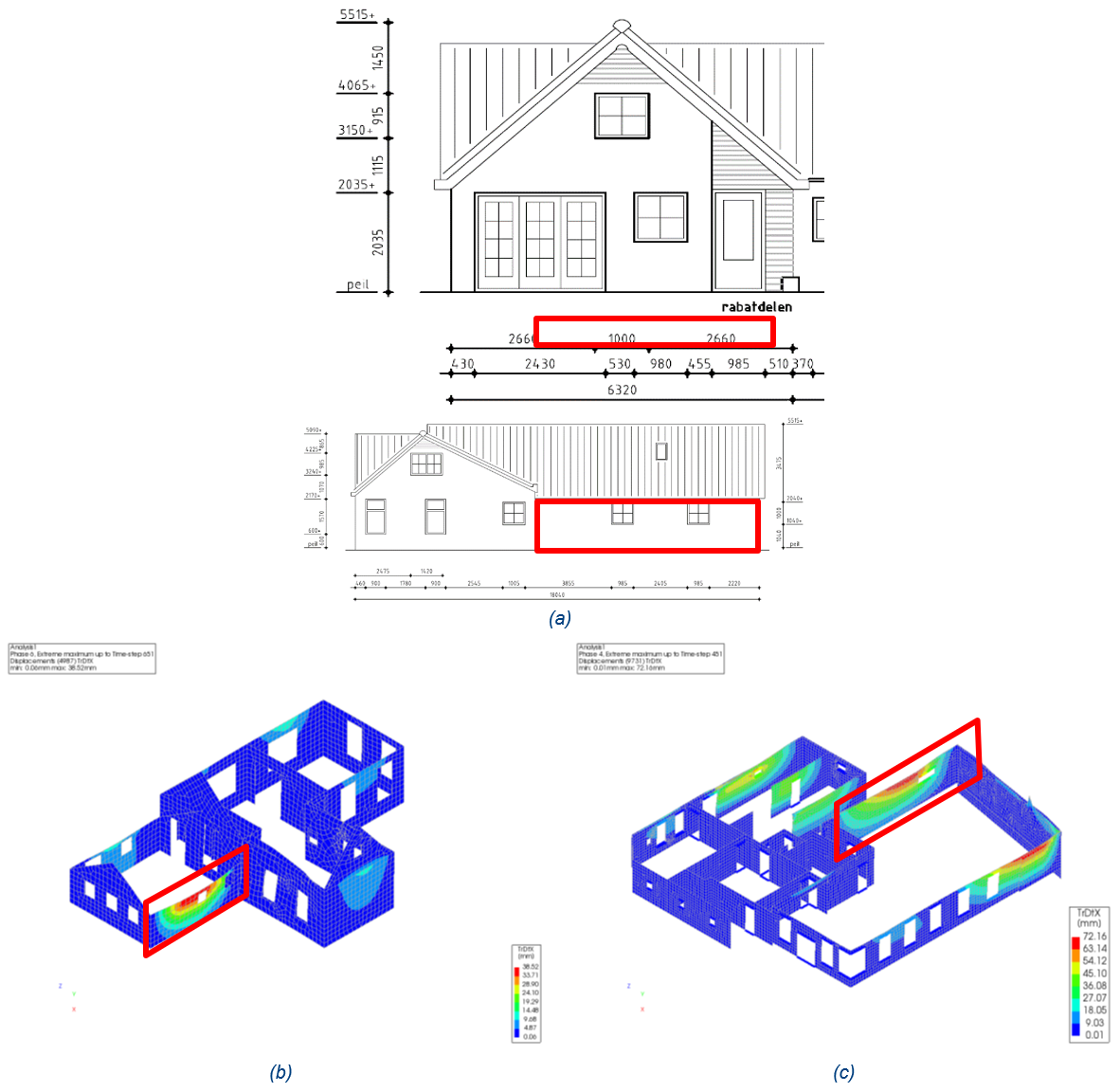
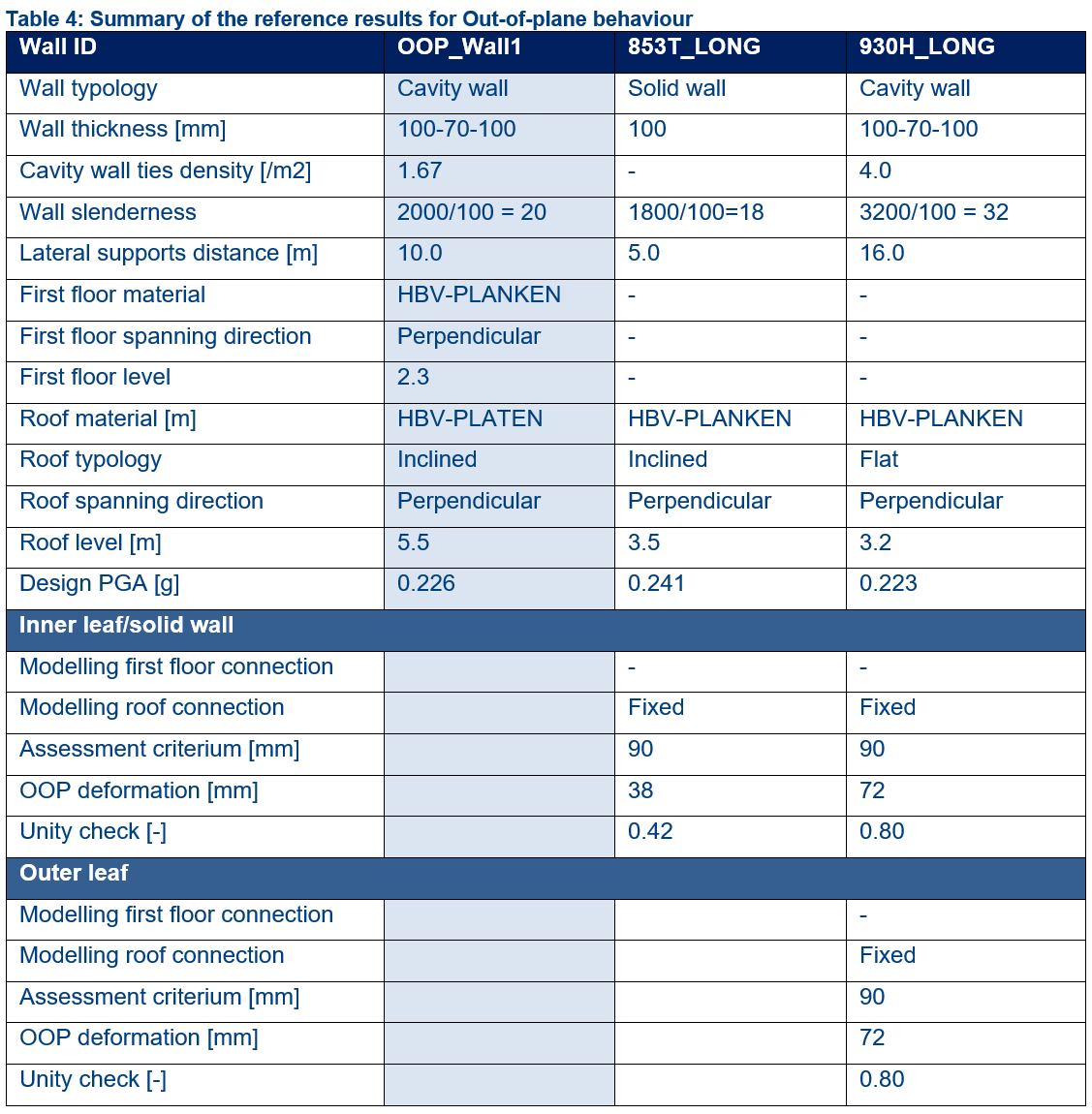
Figure 9.9 shows which wall (highlighted in red) has been considered critical out-of-plane in REF001. It has been
selected as a critical element because of the relatively large distance between its lateral supports. It is expected
that the wall meets the out-of-plane deformation requirement. Table 9.4 shows the comparison of the results between
REF001 and the reference buildings.
Figure 9.11 Out-of-plane behaviour, (a) critical wall in REF001, (b) considered wall for the comparison in 853T(in red colour),
(c) considered wall for the comparison in 930H (in red colour).
Figure 9.12 Summary table of the reference results for Out-of-plane behaviour.
Figure 9.10 shows which wall (highlighted in red) has been considered critical out-of-plane in REF003. It has been
selected as a critical element because of the low overburden load and the weak foundation underneath it. It is expected
that the wall has enough deformation capacity to meet the out-of-plane deformation requirements.
The expectation for the above-mentioned wall has been checked with an NLKA calculation and it has been concluded that no
out-of-plane failure is expected. For the details please refer to the TVA report of REF003.
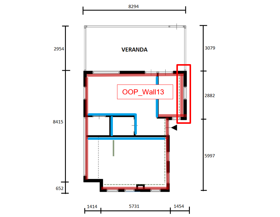
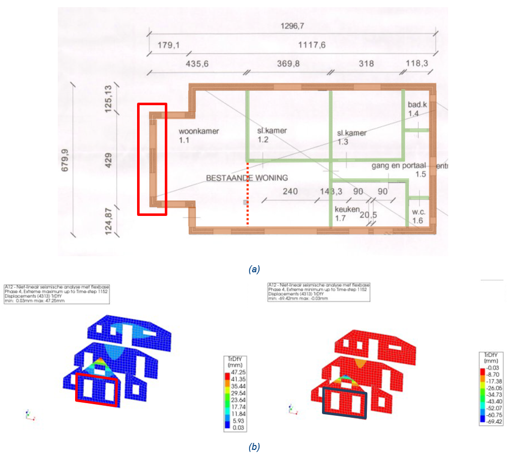
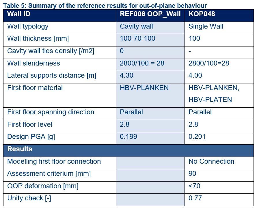
Figure 9.11 shows which wall (highlighted in red) has been considered critical out-of-plane in REF006. It has been
selected as a critical element because of the relatively large distance between its lateral supports. It is expected
that the wall has enough deformation capacity to meet the out-of-plane deformation requirements. Table 9.5 shows the
comparison of the results between REF006 and the reference buildings.
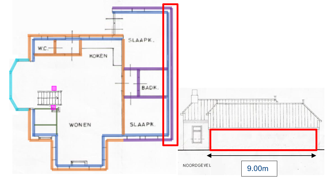
Figure 9.12 shows which wall (highlighted in red) has been considered critical out-of-plane in REF007. The inner leaf of
the cavity wall has been selected as a critical element because of the relatively large distance between its lateral
supports. The walls of the bathroom are considered to not interlock with the inner leaf. It is expected that the wall
does not meet the out-of-plane deformation requirements.
No similar walls have been found within the Reference Approach. Based on engineering experience it is expected that the
wall does not meet the out-of-plane deformation requirements due to the relatively large distance between its lateral
supports and small overburden load. It is expected that also an NLKA (Non-Linear Kinematic Analysis) would not positive
results.
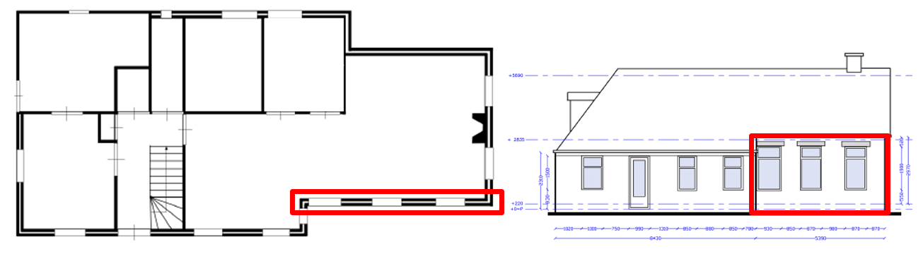
Figure 9.13 shows a cavity wall which was considered to be critical for out-of-plane failure. The outer leaf of the
cavity wall is assumed to be load bearing with most of the roof load resting on the outer leaf. This outer leaf is 100mm
thick and is compared to the 100mm thick façade wall of one of the Krimpje buildings KOP002. KOP002 has a façade wall
with similar openings and carries the weight of a gable wall. Since KOP002 was analysed using NLTH, only the inner leaf
was included in the FE model. In the FE model, this inner leaf was disconnected from the first floor since it was
parallel to the spanning direction of the floor. Thus, this inner leaf is a good reference for a load bearing leaf that
does not have a horizontal support at the first-floor level but complies with out-of-plane deformation requirement. The
overburden load of the gable wall in KOP002 is comparable to the roof load resting on the outer leaf of REF030.
Most of the Krimpje buildings, described in Annex A of the UPR [RA1] have façade inner leaves that carry a gable wall
but disconnected at the first floor level.
For floors that are not continuous and have a missing floor segment, the horizontal forces cannot be transferred to the
walls. Therefore, it is needed to retrofit the floor by adding the missing floor segment and connecting the new floor
segment to the surrounding structure. This ensures diaphragm action in the building.
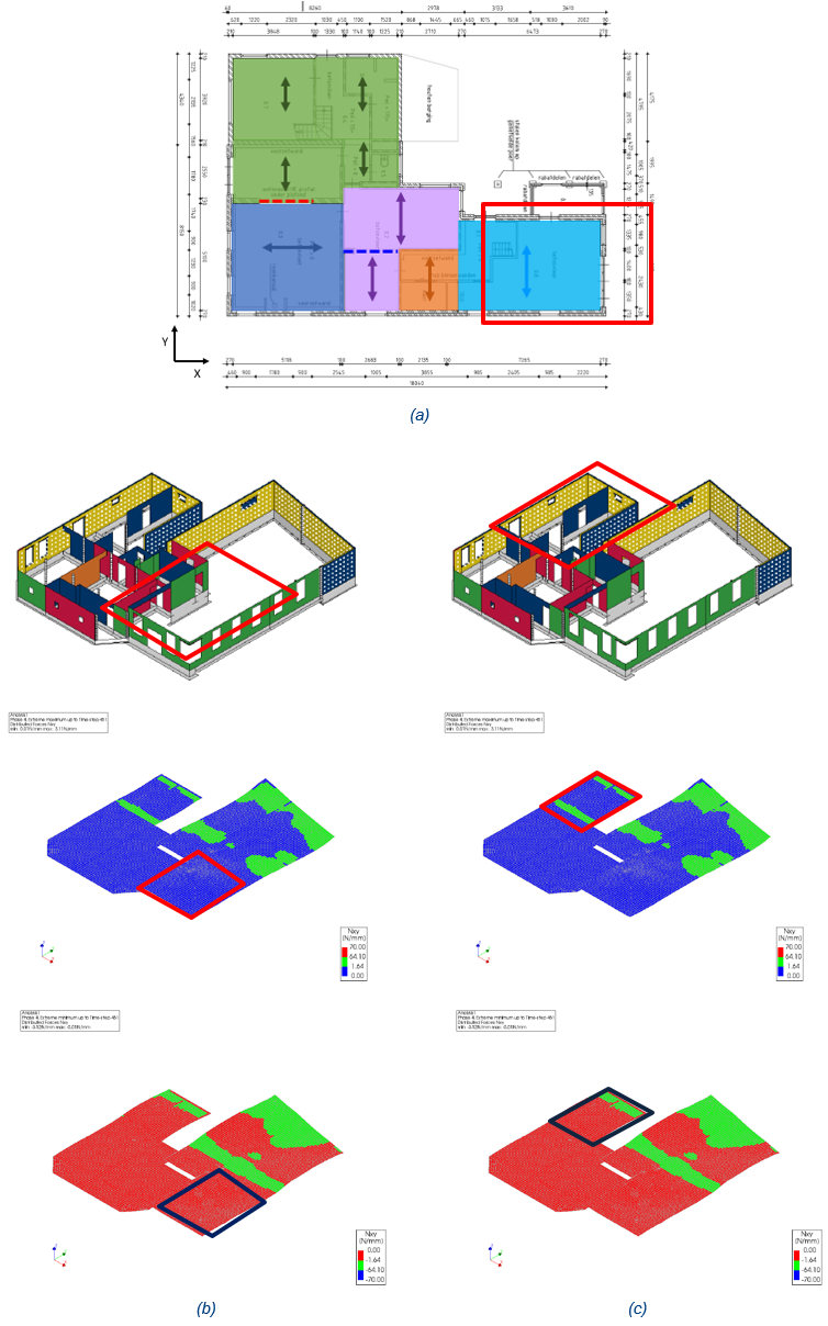
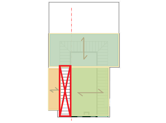
Figure 9.15 shows which floor (highlighted in red) has been considered critical in REF001. It has been selected as a
critical element because in case of an earthquake parallel to Y direction, the floor, needs to transfer the loads to the
supporting masonry walls located at the edge of it. This floor shows to have the largest distance between its supporting
masonry walls and for this reason it has been considered the critical one. In the other part of the building, the floor
diaphragm behaviour is expected to be less critical because of the high wall density and different spanning directions
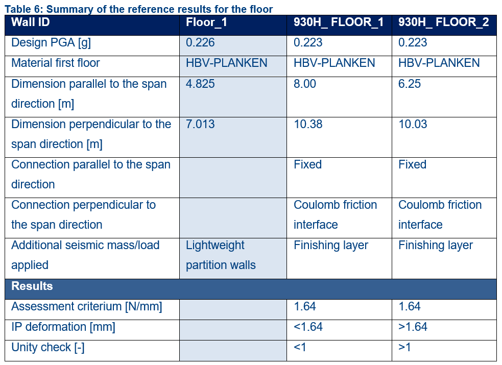
of the floors which creates a unique diaphragm system able to transfer the forces to the load bearing walls. Table 6
shows the comparison of the results between REF001 and the reference buildings.
Figure 9.18 Floor behaviour, (a) critical floor in REF001 (in red colour), (b) considered floor for the comparison
in 930H FLOOR_1 (in red colour), (c) considered wall for the comparison in 930H FLOOR_2 (in red colour).
Figure 9.19 Summary table of the reference results for the floor
For REF003, a floor segment is missing in the first floor (see Figure 9.16). This causes a gap between two floors and
therefore the structure is unable to transfer horizontal forces. To ensure diaphragm action, the missing floor segment
must be added. This will be part of the retrofitting measures advices.
9.4.1.1. ‘Sporenkap met spaanplaat’ (Timber chipboard roof)
Timber chipboards are considered similar to plates; therefore, the behaviour of a roof made with chipboards can be
considered similar to the behaviour of a roof made with plate elements.
The attic floor is considered to be not a structural element; therefore, the behaviour of the roof has to be assessed
without taking into account the presence of the attic floor.
Based on the inspection report or on the available pictures, different materials can be found regarding the roof. Within
the Reference Approach, it has been decided that:
‘Spaanplaat’, translated to ‘chipboard’ in English language, is considered as a plate material
‘Zachtboard’ and ‘Hardboard’ are, instead, considered not structural elements
‘Unidek’ or ‘Dakplaten’ prefab roof panels are considered to have comparable stiffness to planks. However, these
panels are found to have good resistance to wind loads and thus are not believed to fail for EQ loads of magnitude
that is found in Groningen. Thus, these type of roof panels do not require to be strengthened.
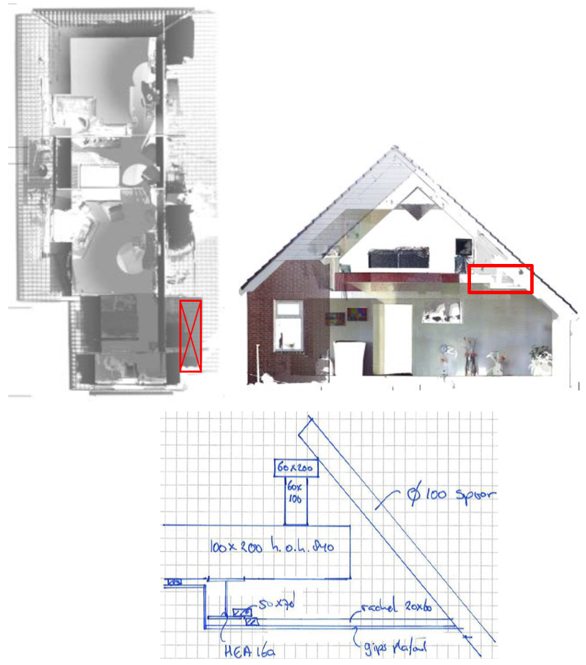
Inclined chimney ducts are critical elements and need to be checked. The duct, due to the high temperature, can show
damages and part of the masonry can fall causing potential hazard.
The chimney duct is considered to be able to withstand horizontal forces only if the masonry material is in good
condition. If this is not the case, then assessment is required.
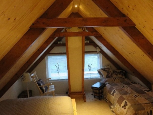
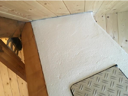
Below some picture of chimney duct are shown.
(a) Chimney duct in good condition. No assessment is required
(b) Chimney duct in bad condition. Assessment is required
Figure - Chimney duct, (a) good condition, (b) bad condition.
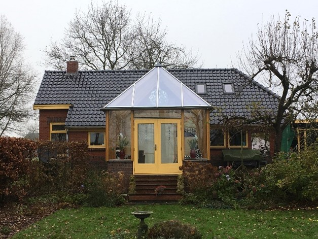
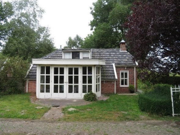
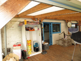
Lightweight timber structures such as portals, porches and conservatories are considered to have enough deformation
capacity and a low seismic mass. It is assumed that the connections in these structures are (usually) sufficient. These
structures do not require further assessment. Below some pictures of lightweight timber structures are shown.
(a)
(b)
(c)
(d)
Figure - (a) Example of a conservatory, (b) Example of a conservatory, (c) Example of a porch, (d) Example of a portal structure.
Balcony’s are usually not considered critical. The vertical seismic load does not have to be taken into account,
according to paragraph 4.3.4.5.2 of the NPR (only at larger cantilevers) and in regards to the horizontal seismic load,
balcony’s can most likely be regarded as flexible enough, to meet the deformation criteria.
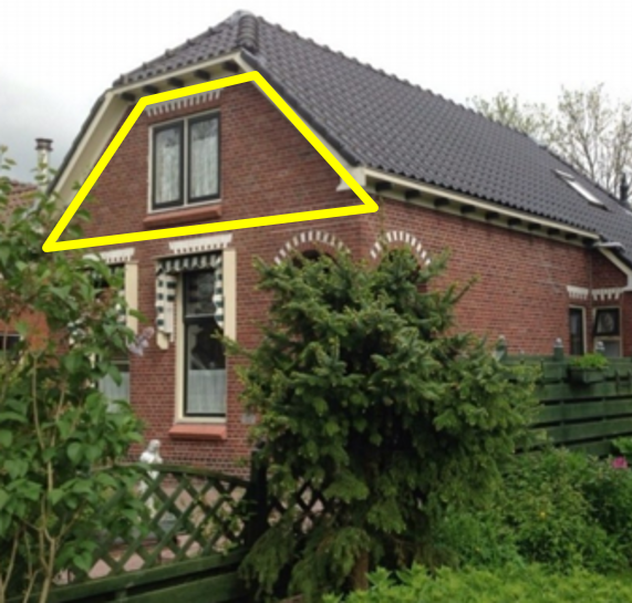
Gable walls are walls located on the ends of a gable roof system thus having triangular shape. Gable walls can be
single-leafed or cavity wall, masonry, or timber. They can be either PSSE or NSCE. If a gable wall is PSSE then it
should be assessed using NLKA [RA3] and if it is NSCE, the Generic risk assessment described in Annex J of the
NPR9998:2020 [RA3] should be used. The method of Annex J is tailor-made to the region of Groningen considering the
local building methods and construction characteristics. This implies that common construction characteristics such as
an adjacent first floor is spanning parallel or perpendicular to the gable wall are considered in the formulation of the
Generic Risk Assessment of Annex J [RA3].
Annex J bases the capacity of gable walls on a probabilistic study of fatality upon failure. The probability that a
person is in an area that the gable wall can fall on during an earthquake and the person is killed are considered in
calculating the acceptable probability of failure of the gable walls. This gives NSCE gable walls a higher acceptable
probability of failure compared to PSSE for the same return period.
An examination of the seismic loading in Groningen shows that gable walls always comply for both time periods T2 and T5
with a return period of 475 years (see section 5.3.5.1 of UPR [RA1]).
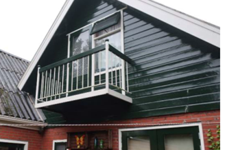
An example of a scenario with both PSSE and NSCE gable walls is a Half-Hipped Roof or ‘Dutch Hip’ construction as shown
in Figure 9.21. These walls are designed to support the rafters of the Half-Hip roof thus are PSSE gable walls. However,
if such a wall is a cavity wall, then the leaf that is PSSE shall be assessed with NLKA and that which is NSCE shall be
treated using the Generic Risk Assessment of Annex J [RA3].
Figure 9.23 Example of Half-Hipped Roof or ‘Dutch Hip’ construction.
9.5.1.5. OOP assessment of outer leaf of Cavity Walls
For NSCE leaves of cavity walls, the procedure of NSCE assessment must be followed. The NLKA tool with zero overburden
load can be used, If the leaf is failing and L4-D measure is believed to be suitable, then this measure needs to be
applied through out the entire area of the wall.
If the outer leaf is required to be connected to the floor through the inner leaf, then it is important to guarantee
that the wall ties used with an L4-D measure have sufficient thickness/diameter.
Figure 9.24 NSCE outer leaf of a long cavity wall which is expected to fail.
9.6.1.1. When is interlocking between walls relevant?
The interlocking between walls become relevant when the amount of load bearing walls is limited.
9.6.1.2. Interlocking between load bearing masonry walls
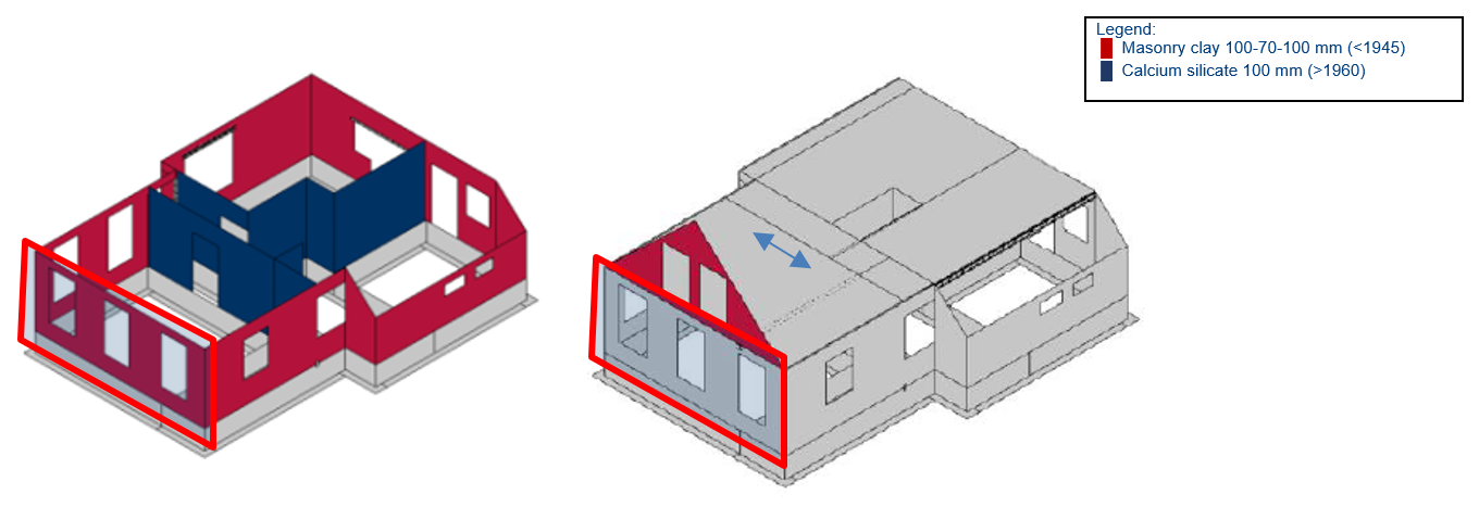
Unless stated otherwise in the inspection report, the connections between load bearing masonry walls made by the same
material are considered to be interlocking in buildings built before the ’80s.
9.6.1.3. Interlocking between non load bearing walls and load bearing walls in buildings built in the ‘80s
Starting from the ‘80s, calcium silicate (KZS) material became more common in the construction and also the way to build
changed, first the load bearing walls were being built and later on, the non-load bearing walls were added to the
structure; therefore load bearing walls and no load bearing walls are considered to not interlock anymore.
9.6.1.4. Connections in buildings built in the ‘80s
Buildings that have been built after 1980 are considered to have efficient connections.
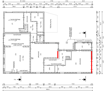
The walls in REF_001 are considered to be properly connected to each other and no retrofitting measures are therefore
needed. Regarding the floor to wall connections, instead, retrofitting measures are needed at the locations indicated in
red colour in Figure 9.23. The walls supporting the floor need to be properly connected to the floor parallel to the
span direction. L2-053 measures need to be applied, in order to guarantee a diaphragm behaviour. The other timber floors
located on the first floor, are considered to work as a whole system; since not all the floors are spanning in the same
direction, good connections are expected perpendicular to the span direction, between the floor and the wall, and
therefore the forces are well spread between all the floors.
Figure 9.25 Location of required retrofitting of floor-wall connection at first floor level.
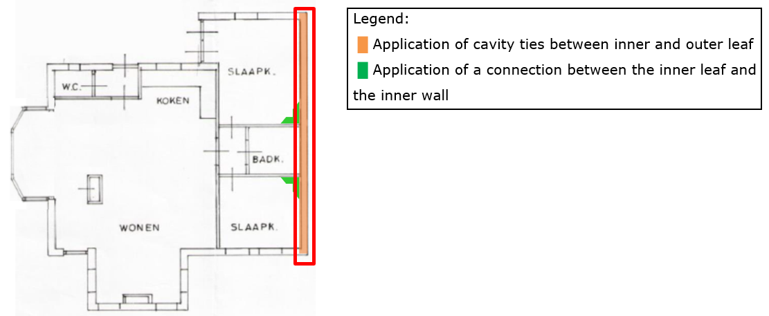
9.6.2.2. REF007: Connection between inner leaf cavity walls and inner walls
Due to the out-of-plane failure of the wall, retrofitting measures needs to be applied. The wall highlighted in red in
the figure below needs to be connected to the inner leaf by applying cavity ties; In addition, it has to be connected to
the perpendicular inner walls.
Figure 9.26 Location of required retrofitting of floor-wall connection at first floor level.
9.7.2.1. Uncertainties about the presence of a foundation element
Sometimes in the inspection report it is not clearly mentioned wherever a foundation element is present or not below a
wall.
In this case the approach to pursue is as follows:
Are any cracks present in the considered location?
Is there any visible deformation in the considered location?
If the answer to both questions is negative, then a foundation element is present to carry the load.
9.7.2.2. Uncertainties about the location of a foundation element
Sometimes in the inspection report it is not clearly mentioned the exact location of the foundation element.
In order to define the location of the foundation element, the span direction of the ground floor should be considered
and also the span dimensions of the floor.
For a timber floor, a span dimension of 5 meter is already a significantly high and therefore a foundation element is
required nearby.
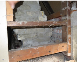
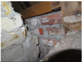
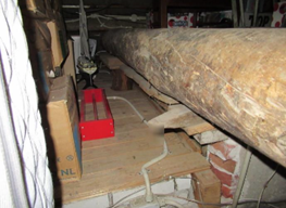
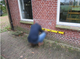
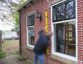
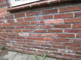
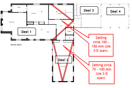
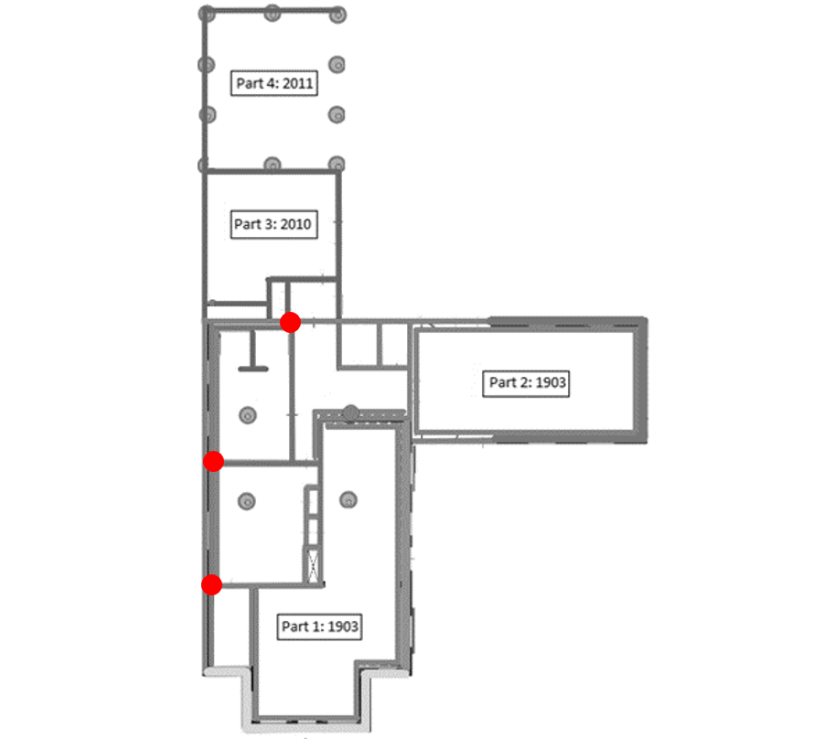
9.7.3.1. REF004: Inclined and damaged walls due to settlements
In the inspection for REF004, it was found that there are strong irregular settlements in the building. This causes the
walls to crack and to have an inclination. The damages in the walls due to settlements can be seen in Figure 9.25. The
settlement in the building can be seen in Figure 9.26. These damages lower the strength of the walls in a seismic
situation. The damage is not so large that the in-plane behaviour is expected to be insufficient during an earthquake.
However, the vertical inclination of the walls is unfavourable for the out-of-plane behaviour of the walls, as it may
cause the walls to tip over sooner. Therefore, it is advised to apply retrofitting measures on the damaged walls, to
ensure that they can withstand seismic loads. For walls with a thickness of 210mm, it is assumed that the wall is thick
enough that the centre of gravity remains within a reasonable range to the wall such that it is not expected to fail
during seismic loading. For inclined/damaged walls, only the walls with a thickness of 100mm need to be retrofitted.
These walls need to be connected to perpendicular walls every five meters. If the wall is part of a cavity wall, cavity
ties need to be applied. For REF004, this results in connecting the left façade to three inner walls and connecting the
back façade to one inner wall (see Figure 9.27).
(a)
(b)
(c)
Figure - (a) Horizontal inclination of a wall, (b) Vertical inclination of a wall, (c) Cracks in a wall