1. Seismic analysis in VIIA
As a result of gas extraction in the Groningen gas field, (induced) earthquakes occur regularly. Due to this seismicity, the risk of complex damage to buildings arises, resulting in potentially unsafe situations. As commissioned by Nationaal Coördinator Groningen (NCG), VIIA (a cooperation between Royal HaskoningDHV and Visser & Smit Bouw) analyses the seismic resistance of buildings in northeast Groningen.
The analysis procedure of VIIA consists of the following steps:
Existing document investigation In order to obtain a reliable insight into the structure of the building, available building plans and construction documents are collected from archives.
Structural survey Inspectors check and validate whether the collected data corresponds to the existing building situation and any missing building data is collected on site.
Engineering By making use of FEM model(s), the engineering department assesses the seismic capacity of the building based on the collected building data. This results in a Technical Retrofit Advisory report on possible retrofitting of the building, in order to comply with the requirements, set in the Dutch code of practice for earthquake resistant buildings (NPR).
Final report The final phase comprises the determination of the advised retrofitting measures, the consequences for the implementation of the advised retrofitting measures, calculation of the associated costs and creating an owner-friendly report of the retrofit advice for the building owner or user.
Various analysis methods are available in the bibliography to evaluate the seismic performance of structures. The selection of a seismic structural analysis type over another depends on the purpose of the analysis, the anticipated performance objectives according to the level of importance of the structure, the acceptable level of uncertainty, the availability of resources, the limitations of the methods and the sufficiency of data. In most cases, local codes or international standards may dictate/recommended the analysis procedure to be used. For the recent NPR9998 version (NPR9998:2020), the seismic analysis methods described in the norm include the linear static (LS), modal response spectrum (MRS), non-linear time history (NLTH) and the non-linear pushover (NLPO) analyses. The latest two, are detailed in annex F and annex G of the NPR9998.
The uncertainty inherent in any each specific structural analysis results depends on several considerations, and even the most complex nonlinear dynamic analyses can lead to higher uncertainty in results than other simpler techniques; for instance, if the nonlinear inelastic properties of the components in the structural model are not reliable, or the input ground motions are not representative for the seismicity of the region. Each analysis type provides advantages and disadvantages and the decision to select a method is according to the building to be analysed.
Within the VIIA project, the workflow for the chosen seismic analysis type consists basically of 5 phases (as observed in the table below). The required actions and outputs will be described in this protocol and the backgrounds for the functions and scripts will be referenced. Each phase provides input to the final deliverables, of which the Engineering Report is the most prominent. The engineering report or TVA (NL: Technisch Versterkings Advies) is our final deliverable for engineering and includes the assessment of the existing situation and the strengthened situation. When only the existing structure is assessed the report is called BSC (NL: Bestaande Situatie Constructie). When the structure is assessed and complies in the report, still we call the deliverable TVA. In addition, there are checks to be performed in each phase, so that the quality of the analysis is guaranteed along the process.
Seismic assessment at VIIA |
|---|
Phase 1 - Starting phase |
Phase 2 - Fixed base model |
Phase 3 - Flexbase model |
Phase 4 - Reporting |
Phase 5 - Strengthening |
The contents of the steps per phase are described on the specific phases. Each phase consists of specific tasks that should be performed to get the input for the final deliverables. Four type of actions can always be distinguished for each phase (observe the table below). These actions do not have to be performed necessarily in a fixed order and may comprise a cyclic process. The viiaPackage provides tools for all four types of actions. The available tools per phase per action type are described on the phase pages and contain references to the specific function documentation of the viiaPackage.
Modelling |
|
C |
Checking |
A |
Analysis |
R |
Reporting |
1.1. Introduction
This report focuses on the workflow to conduct seismic analyses; in other terms, a standardised Protocol to conduct the structural analysis and evaluate the results. It contains information on how to create the model, perform the analysis, handle the results and report for the client. This also entails the automation to be used in the process.
Note
This document is intended for internal use only.
Note
This document is created by the VIIA team and continuously updated by the team, and you!
Note
This protocol is updated for NLTH with DIANA only. The analysis methods that were used in the past have been moved to another section. These are still available, but are not updated as they are not part of the current workflow. This also applies for NLTH in ABAQUS.
The order of chapters follow the workflow. Each step is described and the available tools are presented. Links have been provided to the important documents on box (you should have access to the VIIA box-folders and the VIIA team on MS teams). Each chapter starts with an overview of the steps to be taken, divided into the following sections: modelling, checking, analysing and reporting.
This document is updated frequently, so it is advised to check regularly.
Table - Topics in the protocol |
|
|---|---|
Introduction |
Seismic analysis with viiaPackage |
Phase 1 |
Starting phase (see Phase 1 - Starting phase) |
Phase 2 |
Fixed base model (see Phase 2 - Fixed base model phase) |
Phase 3 |
Flexbase model (see Phase 3 - Flexbase model phase) |
Phase 4 |
NSCE assessment (see Phase 4 - NSCE assessment) |
Phase 5 |
Strengthening (see Phase 5 - Final phase) |
For additional instructions or examples how-to-guides are available on specific topics. In the protocol references are made to these guides.
Finally the protocol contains the reference guide, which contains instructions for scripting. All python functions available in the viiaPackage are present and contain explanation of the function, the required and optional inputs and output it generates. Sometimes examples and additional warnings are provided.
1.1.1. Who to ask
In VIIA we work as one team, and we want you to be part of that team. This means that there is always someone to help you to get the answers of your question. Your first contact is the technical master, which every DIANA team has. He or she can also point you to someone else with more specific knowledge on a specific topic.
If the question requires literature study or research, the knowledge-team is there to do this research. If the question is related to the automation the automating-team can assist. Overall there are also the persons responsible for the analysis method NLTH, NLTH-REF, REF, SBS, NLPO-SDF, NLPO-SLAMA and NLPO-REF.
The current persons responsible for the analysis methods are:
Table - Responsible for the analysis method |
|
|---|---|
NLTH |
Reinier Ringers |
MRS |
Rene Meravy |
REF (NLTH-REF) |
Maurice Hermens |
SBS |
Evangelos Goulas |
NLPO-SDF |
Maurice Hermens |
NLPO-SLAMA |
Maurice Hermens |
1.2. Non-Linear analysis methods and knowledge development
1.2.1. Fundamentals
The authors of this document assume that the basic knowledge about dynamics and earthquakes is known. The earthquakes in Groningen are so-called induced earthquakes. These arise from gas production activities in contrast to the well-known tectonic earthquakes. From TU Delft, the most important concepts concerning these induced earthquakes are explained in online teaching materials. This can be seen via the following LINK.
The topics of the lectures are as follows:
Seismic risk
Seismic activity
Basic seismic concept
Behavior of buildings under seismic load
Seismic assessment and reinforcement measures
The understanding of the topics from lectures are important when working with this protocol. It is therefore advisable to go through these lectures one by one.
1.2.2. Knowledge development
This protocol document focuses on production. Knowledge development is done in the knowledge-team, and once finalised will be added to this protocol or basis of design (BoD). For research, there is a distinction between object-specific knowledge and general knowledge. If it only applies to the object, it is permitted to perform a short side study. This should be discussed with the lead engineer. The study should have a maximum duration of two weeks. It may be also the case of knowledge development opportunities that are important for several objects. For these studies, a separate budget must be requested. This is done in consultation with the lead engineer and the head of the knowledge-team.
1.2.3. What is NLTH?
In a non-linear time history analysis, NLTH, the structural model is subjected to recorded or artificial earthquake signals at the base of the building and non-linear material properties are used. The signal contains x, y and z components that are applied at the same time. The length of the signal is usually about 10 seconds (for earthquakes in Groningen). The nonlinear analysis is performed per timestep. Here two methods can be used to find the solution: implicit or explicit method.
In VIIA the implicit method is performed with DIANA software. The analysis is performed with a numerical iteration method (eg Newton-Raphson). In order to be able to follow the signal characteristics, the size of the timestep sizes should be small (max 0.01 s approximately), although this is larger than the explicit method. If the steps are too big, the behaviour will not be well described and the velocities and accelerations will be imposed at once, which can lead to great forces (amplification of the dynamic behaviour). Too small timestep costs more analysis time.
During the analysis, an equilibrium with a corresponding tolerance will be sought per time-step. For this, use is made of the first stiffness matrix. If the convergence criterion is met, the next time-step is continued. If it is not achieved, the stiffness matrix will be adjusted and another balance will be sought. If no equilibrium can be found during the same time-step and the deviation (read: the error) is too high, the analysis will diverge and the calculation will be aborted. A non equilibrium condition case can occur for brittle failure of a component in the structure.
In VIIA the explicit method is performed with ABAQUS software, although this is currently not used. For an explicit solver no convergence criteria is checked. Therefore, the timestep (in ABAQUS called increment) should be sufficiently small to ensure stable analysis. The size of the step depends on the element size, stiffness and density of the material. Furthermore, the stiffness proportional damping parameter of Reighley damping. In essence the deformation wave speed trough a material should not travel further than a distance of one element within one calculation step (called increment in ABAQUS). To read the theory behind the wave speed abd stable time in explicit calculation reference ABAQUS documentation. For practical reasons for VIIA projects a time step of 5E-6s is used. If the steps are too big, the behaviour will not be well described and the velocities and accelerations will be imposed at which can lead to great forces (amplification of the dynamic behaviour). Too small timestep costs more analysis time.
1.2.4. When to use the NLTH method
Different from NLPO, NLTH analysis can be used for any structural complexity (observe also Figure 198). It’s use limitation may be related to the quality of the available information (poor initial information may produce unreliable results; here, rather a simple method may be preferred) and the available resources for the object (time and budget). The use of the method may be also related to the requirements of the building owner and the structure importance.
Some advantages that justifies the use of typical set-up NLTH over MRS analysis are:
The soil behaviour may be modelled, which can account for damping or amplification effect.
The soil-structure interaction is modelled, which can result in additional damping effect.
Use of nonlinear material properties (over-strength and displacement capacity)
Integrated assessment of Out-of-plane behavior with the in-place (also less failure occurrence observed).
It is possible to model complex connection types.
Precise calculation of displacements.
It is possible to apply nonlinear springs in a dynamic analysis.
Visualisation of the expected failure process/mechanism can be observed more clear for non-linear analyzes.
Proposed strengthening measures generally are less conservative and therefore a reduction of strengthening costs is achieved.
Disadvantages of NLTH to MRS analysis are:
Processing time is considerably longer and therefore higher costs for engineering. Calculations may take several days, which limits recalculations possibilities and required high certainty of the model use previous to perform the seismic analysis.
Modelling errors are more difficult to track.
Brittle failure of, added to the model, non-structural element may cause divergence and stop the analysis prematurely
Developments in the method are ongoing.
Generally speaking, NLTH analysis presents advantages with respect to MRS when it is expected form experience that MRS analysis will produce extensive amount of measures. The expectation (from experience) is that a NLTH analysis will result in a significant reduction in the number of measures.
1.3. DIANA process
The models in DIANA FEA software are complex and contain lots of detailed information. This means that mistakes can easily be made, and that the cause is not always clear. The workflow process for DIANA presented here aim to prevent errors, by applying complexity in small steps. In this section, the DIANA specific actions are described in order to obtain a reliable model. The steps are described in the subsequent sections.
1.3.1. Version
Currently the models are built and calculated in DIANA Release 11.0, d.d. 2025-12-08. This is also the version available on the servers where this viiaPackage is working on. It may be that with a new release the syntax, or the operation of the software, has changed. In a newer version, the functions of the viiaPackage can have an unexpected result or even cause errors. When a new version of DIANA is released, the knowledgeteam will perform validation analyses. Then the Basis of Design is updated. The structural engineer should perform the analyses according to the version mentioned in the Basis of Design used.
The indicated version of DIANA can be found here (in the same folder you will also find the older and newer releases). LINK Current version DIANA
The following tutorial shows the procedure to install a new version of DIANA software (version 10.9 in this example).
1.3.2. Licenses
RHDHV has a limited of licenses for the use of DIANA that are updated annually. The experience is that a licensing update does not go smoothly and that, with regard to the expiration of the license, this must be taken into account when using the license in that period.
DIANA works with modules for which different a number of licenses are available. The current distribution of the licenses is as follows:
Table - Network licenses DIANA (2026) |
||
|---|---|---|
Module |
Number of licenses |
Description module |
BASIC |
50 |
Pre- / Post-Processing with DIANA
Import CAD models (IGES, STEP, IFC)
Geometrical modelling
Auto-meshing (2D, 3D, incl. hybrid mesher)
Post-processing features
Capacity result checks
Report generator
Materials:
- Basic linear
- Basic nonlinear models (Von Mises and Mohr Coulomb)
Analysis:
- Linear static analysis
- Eigen value analysis
- Basic phased analysis
- Unlimited model-size, parallel processing
Elements:
- All the structural elements (including Tension only / compression only
- interface elements)
|
EXPERT |
50 |
BASIC MODULE REQUIRED
Materials:
Nonlinear material models
Nonlinear structural interface models
Analysis:
Nonlinear analysis features
Geometrical nonlinear analysis
Phased analysis in conjunction with nonlinear analysis
Stiffness adaptation analysis
Reinforcement design checks
Engineering creep
Engineering liquefaction
Groundwater flow analysis (Steady state and transient)
Buckling analysis
Modal, spectral response and frequency response analysis
Transient analysis (linear)
Elements:
Pile Elements
User Supplied Subroutines
|
HEAT |
50 |
BASIC MODULE REQUIRED
Analysis:
- Heat transfer analysis (Steady state)
- Young hardening analysis
- Staggered heat stress analysis
Elements:
- Boundary elements
- Cooling pipes
|
STRUCTURAL I |
50 |
BASIC & EXPERT MODULES REQUIRED
Materials:
- Total strain crack model
- Multi-directional crack model
- Nonlinear reinforcement models
- Bond-slip reinforcement
- Creep and shrinkage
- Rankine Hill
Analysis:
- Transient analysis (Nonlinear)
Elements
- Boundary elements
|
STRUCTURAL II |
50 |
BASIC & EXPERT MODULES REQUIRED
Materials:
- Maekawa Fukuura model
- Modified two surface model
- Nonlinear reinforcement model
- Bond-slip reinforcement
- Engineering masonry model
Analysis:
- Transient analysis (Nonlinear)
Elements:
- Boundary elements
|
GEOTECH |
50 |
BASIC & EXPERT MODULES REQUIRED
Materials:
- Conventional and advanced soil and rock models
- Nonlinear interface models
Analysis:
- Slope stability analysis
- Mixture analysis
- Transient nonlinear analysis
Elements:
- Boundary elements
|
ADVANCED DYNAMICS |
50 |
BASIC & EXPERT MODULES REQUIRED
Materials:
- Fluid-structure interface models
- PML
Analysis:
- HTFD analysis
- Transient nonlinear analysis
Elements:
- Boundary elements
|
LIQUEFACTION |
50 |
BASIC & EXPERT MODULES REQUIRED
Materials:
- UBC Sand model
- JAPANESE Liquefaction Models (Bowl, Nishi, Towhata-Iai)
|
DIANA SUPPORT |
50 |
|
In the Sentinel Admin Control Center the DIANA network license should be specified, LINK. Select the Configuration in the menu on the left side. In the tab Access to Remote License Managers you can specify the license in Remote License Search Parameters. Currently the RHDHV licenses managed by WPS are in server NLOUMFOPLIC051.
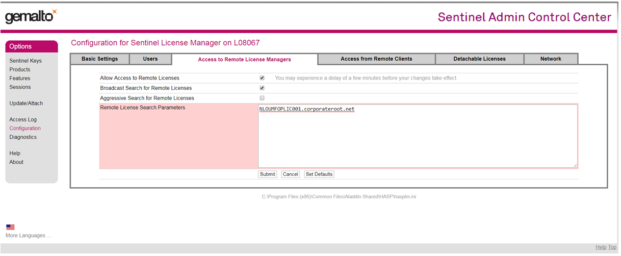
Figure 1.1 Specifying the RHDHV network license for DIANA software.
In the Sentinel Admin Control Center you can also see the number of available licenses. You can find those here: LINK.
When you experience issues with the license you should contact WPS. Note that the licenses will only be available if you have access to the RHDHV network (with AlwaysOn-UserTunnel active).
1.3.3. Installing the viiaPackage for DIANA
To prepare DIANA for using in the VIIA project please read the instructions in the following guide: How to install the viiaPackage.
1.3.4. Preparing the DIANA Environment
To setup your DIANA environment please read the instructions in How to set-up DIANA.
1.3.5. Servers
RHDHV currently has multiple servers dedicated for the VIIA project where calculations can be performed with DIANA software. These use the network licenses, in the same way as DIANA licences, are used on local laptop (they are coupled to the person logging in). Experience is that the servers are generally not quicker to perform the calculations, but they ensure that long calculations can continue, that the laptop remains available for other purposes and that large files remain manageable.
Note
The servers are not connected to the box-folders and are not intended to store data. There is no back-up of the data.
For more information on the servers: How to use the VIIA servers.
1.3.6. Performing analyses in DIANA
To perform calculations in DIANA, an analysis must be created. For the settings and explanation in the dcf-file (the file with the analysis settings for DIANA), refer to How to DCF settings. Running the analysis can be done directly in the graphical user interface (GUI) of DIANA, or by running it in a Command Box.
A point of attention is the export of data. The more output selected, the slower the calculation runs. While the calculation is running in DIANA GUI, the program cannot be used. You can continue working by saving the model and opening a second window with the model. Performing calculations and working through the model can then be done simultaneously. It is also possible to carry out a calculation via the Command Box. The advantage of calculating in the Command Box is that the interim results can be viewed during the calculation.
To calculate in the Command Box, the model must be exported to a dat-file and the analysis exported to a dcf-file. The following syntax must be added to the dcf-file:
* FILOS
INITIA
* INPUT
To start a calculation, navigate through the Command Box to the correct path and use the following syntax:
>>> diana -m name.dat name.dcf
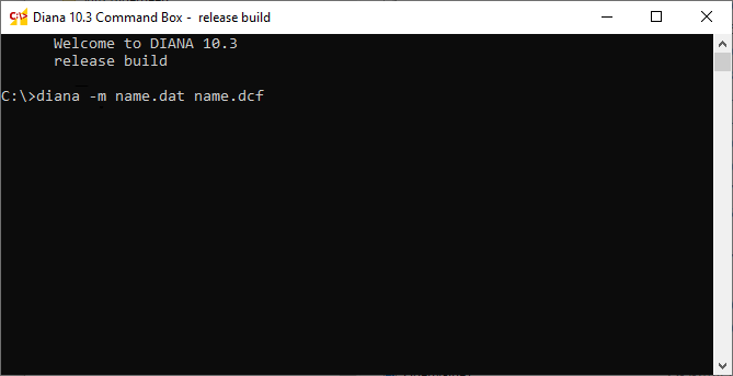
Figure 1.2 Calculations via the DIANA Command Box.
The advice is to create a folder per calculation, so that calculation files and result files remain bundled. This prevents confusion about which .dat and .dcf to which .dnb belongs. A new calculation in the same folder with the same output filename will overwrite the old files. The functions in the viiaPackage will help in this process.
1.3.7. Bug fixing in DIANA
It is possible that DIANA gives errors during an analysis. These error messages are due to incorrect modelling or because DIANA is a program in development and therefore not always work properly. In the latter case, a workaround is usually required (and available for known errors). The error messages are generally described very cryptical. Errors are tracked with the solutions found so far. If you encounter an error that is not in this log yet, please add it.
As a second step, it is advisable to ask a colleague for help. It may be that this error is already known. If the problem is not solved yet, contact DIANA support. Do not forget to add the error’s solution to the log so that the next colleague that encounters the error can also benefit from your experience!
1.3.8. Convergence
It is important to check the convergence of your numerical calculation. If the solution is not converging, it may be that the solution is not correct, even if the calculation is completed.
In non-linear calculations, a balance must be sought in each time or load step in terms of forces and displacements. Due to both, geometric and physical nonlinear effects in the model, it is necessary to perform iteration in order to achieve a balance of forces and displacements. In the first iteration a solution is tried in which the problem is linearised. The stiffness matrix used in this case depends on the chosen iteration method (Newton-Raphson, Secant, Linear stiffness). First of all, the following steps are taken:
Based on the chosen stiffness matrix and the external forces on the model (gravity and inertia forces) the corresponding displacement in the nodes is calculated.
With this displacement, the strains are determined in the integration points of the elements.
The strains in the integration points are then used to determine the stresses defined in the stress-strain curve of the selected material model.
The stresses are then recalculated back into forces at the locations of the nodes of the model.
When non-linearity occurs in the model there will be a difference between the external force and the internal force, which is called the ‘out-of-balance force’. When there is no iteration, the solution found will deviate from the true equilibrium path as shown in the figure underneath.
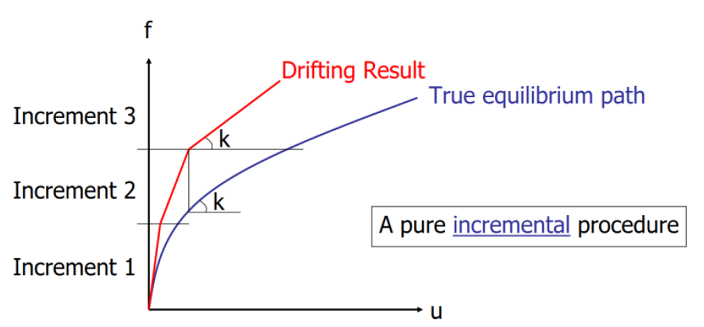
Figure 1.3 Deviation of the solution when it is not being iterated [source: presentation ‘Computation modeling of Structures’, Max A.N. Hendriks].
Instead of stopping the calculation at step 4, step 1 is started again, with the external force now being the out-of-balance force. Depending on the iteration method, the stiffness matrix is also updated in this step. In step 4 an ‘out-of-balance force’ has again been calculated. This is normally smaller than the first iteration. When the iteration process is successful, a displacement field is found in which the external forces (approximately) are in balance with the internal forces as shown in the following figure.
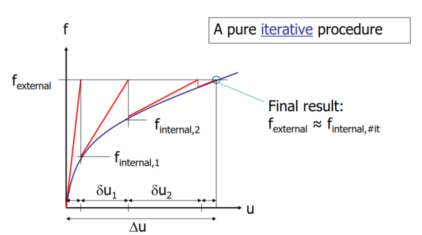
Figure 1.4 Iteration procedure where equilibrium is found [source: presentation ‘Computation modeling of Structures’, Max A.N. Hendriks].
Eventually there will always be a small unbalance between the internal and external forces. The established convergence criterion determines when iterating stops. A force, displacement or energy criterion can be selected for this.
The force criterion states how much smaller the ‘out-of-balance force’ must be than the applied external force in the first step. The displacement criterion sets how small the deformation increase in the last step must be compared to the deformation in the first step. The energy criterion states how many times the stored energy should be in the last iteration compared to the first iteration. Note that the energy criteria is a combination of the force and displacement criterion.
The figure underneath shows an example of the out-file that is generated when running an analysis in DIANA. Here, among other things, the iteration process is reported. In this example, a displacement criterion and force criterion is set.
The different aspects of the iteration process, such as these can be found in the out-file, are explained here:
In the red block, the norm of the displacement and force vector is displayed. In addition, the corresponding convergence criteria (0.01) is displayed. In this load step the out-of-balance force or the displacement increase in an iteration step must be 100 times smaller.
In orange, you can see how many times the out-of-balance force is smaller than the initial force norm. When this factor is more than 100 times smaller, there is no need to further iterate and the next load-step can be applied. At this moment there is no known displacement increase. This is therefore not yet shown.
The results of the first and second iteration are displayed in the blue blocks. In this case, the displacement criterion is reached in the second iteration and the load step can be completed.
Information about the non-linearity occurring in the load step is given in the green block. Here it is indicated in how many integration points the stress state is in the plastic or cracked area. When many new points (PLAST NEW for plasticity and ARISES for cracks) occur, this indicates a lot of non-linearity.
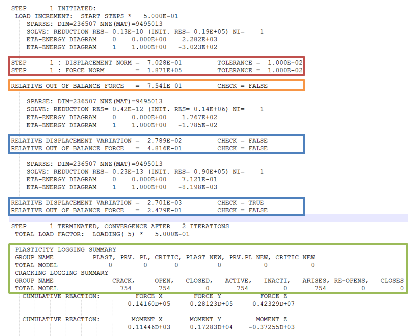
Figure 1.5 Example of an out-file.
1.3.9. Non-converged time/load steps
The convergence criterion (as described in the previous section) describes the relative accuracy. If the convergence criterion is not met at the end of a time/load step, then this is called a non-converged step.
In the case of non-converging steps, it must be assessed whether the results are reliable. This can be done by comparing the displacements around the non-converged steps. If there is no sudden change in the deformations then this is acceptable. See also analyseCalculation-label).
1.3.10. Divergence
If the unbalance in a time step is bigger than a certain value, this is called divergence. No solution is found and this is often accompanied by enormous displacements and accelerations. In case of divergence, the cause must be sought so that this issue can be resolved.
There are roughly two reasons for divergence. The first is that the construction fails (building or a building component) and no balance can be found. The second reason is that no balance can be found due to discontinuities in the model (numerical divergence). It will probably occur several times during the workflow that the second reason for divergence is found.
Possible divergence due to discontinuities in the model:
Geometry (elements are not connected properly)
Material parameters (parameters or orientations are not correct)
Supports (too small or too many degrees of freedom)
Loadings (too large (loading steps) or incorrectly applied)
DCF (iteration scheme)
Divergence in linear static and/or eigenvalue analysis:
Check your supports, usually the translation degrees are well supported but often the rotational degrees of freedom are forgotten at the locations of beams and foundation piles.
Check for low-high stiffness connections (eg for interface elements K > 1E+05N/mm3) or large stiffness differences in your model
DIANA FEA suggest that if the eigenvalue cannot be solved, the shift frequency (in analysis setup) can be change to 10Hz. This may help the user to detect singularities (mechanisms, loose elements, etc)
Always output the rotations in the eigenvalue analysis and check them! Often, rotations around the own axis of beam elements are forgotten.
Divergence in NL analysis:
Step back > first static non-linear > or further back eigenvalue analysis
View the displacements, cracks, accelerations and residual forces in the steps just before divergence. Usually the problem is located where these are big. Make this part linear or change the stiffness.
When the calculation diverges in the first step, it is often after multiple iterations, however, when you look at divergent results, this can sometimes give a distorted picture > perform the first step with one iteration and then check the results of the non-converged step, perhaps this gives more information.
Have the previous steps been properly converged? > If the previous steps do not converge properly, it can also be physically collapsing the structure.
Use a different iteration method, smaller time steps or smaller convergence criteria.
DIANA may have difficulty when switching from compression to tension (vice versa) in non-linear interfaces, the difference in stiffness is difficult to solve and can sometimes cause problems, reducing stiffness can help.
Turn non-linearities into material parameters or the dcf. Geometric linear computing can also help. For masonry there is also an option to make the material linear when it cracks.
1.4. ABAQUS
As the NLTH with ABAQUS software is not currently part of the workflow, the extensions for the protocol have been moved to a separate page, which will not be updated with new developments. The additions for the NLTH process with ABAQUS can be found here: Seismic analysis with NLTH in ABAQUS in VIIA.
1.5. Python process
The python console in DIANA makes it possible to model fast and accurately. The ultimate goal is to reduce the modelling time, so that more time can be spent on interpreting the results and optimising the advice to the client. This requires scripts and structure. In this section the method with python that is used within VIIA is described.
If the installation procedure is followed as intended a python script called the modelscript is added to the working folder. The modelscript contains the setup, adjustments, updates and preparations for the model. It generates a json-file with the complete structure; excluding: earthquake loads, supports, connections, analyses and results. This json-file is saved in a sub-folder of the working folder called ‘model’.
The mainscript is used to perform the required analyses for the assessment. This part of the process requires a different settings for imposed loads, earthquake loads, supports, (interface) connections, analyses and result handling. The mainscript is located in the working folder. All results are saved to subsequent sub-folders. The mainscript can be used to create, run an analysis and result handling.
The result-script is used for result handling of analyses that require significant processing time. It loads the model, reads the results of the analyses and creates the required outputs (graphs, pictures and processed data).
The viiaPackage is a toolbox - developed by VIIA - for modelling and evaluating of buildings to provide advice about their earthquake performance that can be called in the mainscript or in the DIANA GUI. Although the viiaPackage tools can be applied widely, the described steps in these pages is limited to the application of the viiaPackage for NLTH processes. The package contains scripts that can be used to create a nonlinear model. It also contains the FEM library, with all elements of the model. This makes it possible to apply scripts to specific parts of the object. The latest version of the viiaPackage is periodically updated, the functions in the viiaPackage are documented in the documentation on these pages. Here you can find which input is required for the function, but also what the output is. The limitations and warnings are also included here.
It is the job of the structural engineer to apply the right tools from the viiaPackage to arrive to a functional model. The functionality in the viiaPackage is only a tool for you as structural engineer!
1.5.1. viiaPackage
The viiaPackage contains the complete set of engineering tools developed by VIIA.
Each function is made according to the python constitution. Study this before you start programming. This means that the scripts have the same format and is well documented. Users should be able to understand how to use the proposed function and the procedure must be clear for future developments (by others than the original scripter). For more about the constitution for Python in VIIA: LINK
from viiapackage import *
A conversion script is used to link between the viiaPackage and the syntax used in DIANA.
Running a script can be done in several ways: by running from a menu in DIANA (preferred way if the package is used) or by copying the text of the py-script in the command console of DIANA.
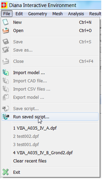
Figure 1.6 Run script from menu in DIANA.
The functions in the viiaPackage will give notification of the process, any error will be reported in the command console in the screen and in the log (you can find in the working directory).
When closing the model in DIANA, be sure to close the whole program, otherwise the python session will not abort and influence any new applied functions. The python should also be reloaded if any changes are applied to the mainscript, modelscript, result-script or any module of the viiaPackage.
The package is currently managed by Reinier Ringers. He is responsible for the collection of new scripts, improvements and ensures the quality. Periodically a new version is released, of which registered users will receive an e-mail notification. Bugs should be reported directly to the administrator.
1.5.2. Python scripts
In the different scripts all actions that needs to be taken are recorded. The aim is to keep this script as clean as possible, so that the various actions are clear and can be checked easily. For the different scripts templates are available.
For all actions in the GUI that are not executed via functions, the corresponding syntax must be included in this py-file. Special attention must be paid to assigning the classifications, etc. - as is done in the model script - when new elements are added.
Class functions (methods) All functions in the VIIAClassDefinition can be called as follows (example color_me functionality):
for shape in project.collections.shapes:
    shape.color_me()
Here, the color_me() method is applied to all elements in the Shapes list. The function can also be used on all floors, for example:
for floor in project.collections.floors:
    floor.color_me()
Individual elements within a class can also be accessed. The above function can also be assigned to, for example, the wall with the name N0-WANDEN-MW-KLEI> 1945-110-76 by:
wall76.color_me()
See the documentation for a further explanation per functionality (detailed descriptions of what the function does and what it does not). Pay attention to the order of applying functions. First make the geometry correct and then add the operations such as connections / interfaces and model cavity walls. Only then, assign the corresponding properties.
1.6. Python
For the use of python in the VIIA project, more information can be found here:
For the use of python in the viiaPackage, a number of items in this chapter are explained in detail.
1.6.1. Python editor
A python editor is a program with which you can edit the python syntax. Notepad++ is an editor that can be used in a basic way for most use. However, it can not run the scripts in a console. Therefore you can use DIANA for this, but it has few possibilities to check variables during the process.
Notepad++: LINK
If you want to have more options when scripting you should work in a dedicated python editor. There are several python editors available. The preferred editor is PyCharm, but others can be used as well:
PY Editors: LINK
Warning
If you use PYCharm, you don’t have to use the Professional edition, you can use the free Community edition.
Note that when you run the scripts in an editor, you can not use functions that request information from DIANA. We are trying to develop the viiaPackage where these information requests are limited, and to perform as many operations as possible in python.
1.6.2. Functions in python
Functions in DIANA form a relationship between a set of input parameters and a set of allowed output. Functions are called by typing in the command console or calling in a script. For example, the function
createSheet ("Sheet 1", [[0,0,0], [1,0,0], [1,1,0], [0,1,0]])
creates a plane named ‘Sheet 1’ with nodes (0,0,0), (1,0,0), (1,1,0) and (0,1,0). Similar functions can be generated in python. In the viiaPackage all functions are lowercase:
viia_create_sheet()
A function block starts with the syntax: def followed by the function name, parentheses and a colon. All parameters or arguments must be given between parentheses. To distinguish between DIANA’s own functions, all functions defined by VIIA start with viia:
def viia_function_name(parameter1: str, parameter2: float):
A description of the function is included in the VIIA functions. The description describes what the function does, which input is required, what the output is and what is required for proper operation. This can be requested in DIANA in the command console with:
help(viia_function_name)
The description shown is on the first line of the function in brackets, and is called the docstring.
def viia_function_name(parameter1: str, parameter2: float) -> str:
    """
    This function does, etc.

    Input:
        - parameter1 (str): Parameter does. For example ..
        - parameter2 (float): Parameter does, in [m]. Default value is 1.0.

    Output
        - Function returns a string and/or changes some setting.
    """
In the viiaPackage documentation, there is more information on how to use the function. You can call for the function by:
viia_help()
A function can also be entered directly in the GUI of DIANA or read by means of a script.
1.6.3. Git
The viiaPackage repository is located on git, Azure Devops. For active development you require a license. The automation team has access for development and maintenance. As a user of the viiaPackage we encourage you to share your scripts with them, so the rest of the team benefits too. For the use of git refer to the VIIA manual for git: LINK
You don’t need the license to install the package. You do require access, which can be requested via Reinier Ringers. For installation procedure with pip refer to _installation-label.
1.7. Other tools used in VIIA
1.7.1. JIRA
In VIIA engineering we use the SCRUM methodology. For each team and for the automating team we have scrum-boards in JIRA. Access should be requested via ICT software order portal. After receiving access, contact Ruben Vorderegger to be added to the required board (which team are you participating in).
1.7.2. MYVVIA and engineering database
The wish to save our project data centrally and on a structured way has been fulfilled whit this data management system. Beside this the data tool should give us a better insight to the progress of our project.
Please contact the development team if you have any questions about the tool: MYVIIA Datatool.
When running your modelscript, mainscript or resultscript information is gathered from MYVVIA. Also information from analyses is sent to the database in the scripts. To facilitate this you need to create a user_config file, which must be located in your working directory. It contains the credentials to connect to the database. In the start tool this is automatically created. Install with the instructions in this protocol.
On MYVIIA also engineering information is collected for data analyses within VIIA and for the reference approach. Contact Elisa Paletti for more information.
MYVIIA is also used to communicate and send or retrieve data to other disciplines.
1.7.3. Templates
For many scripts templates are available in the template folder in the viiaPackage. For example engineering reports, CAD layer settings, and the modelscript, mainscripts and resultscript for the different analysis-methods are available and updated there.
When the clean installation procedure is followed, the correct templates are prepared and prefilled.
1.7.4. Verified Excel sheets
For VIIA several Excel sheets are available. These are regularly improved, updated and release in a box folder. Be sure you use the latest and approved version from box each time. Check the folder: LINK
Warning
Don’t use Excel-sheets from other locations as they are not verified properly or they might have been updated since. The files here are maintained by the knowledge-team.
Starting the NLTH process is described in the next page: ‘Starting phase’.