This guide contains the procedures for the assessment of the non-seismic structural elements (NSCE). Part of that
assessment is performed with the non-linear kinematic analysis, which is treated in a separate part in this guide.
This guide is maintained by the task force NSCE and the task force NLKA. If you have any questions while performing
these procedures, please use the teams channel
NLKA and NSCE.
Warning
The NLKA method shall not be performed for the cantilever walls with slenderness (height over thickness)
20 and greater. Therefore, any NLKA results are NOT valid for the following cases:
Cantilever wall with a height of 4.2m and greater (thickness 0.21m).
Cantilever wall with a height of 2m and greater (thickness 0.1m).
Those walls will collapse during an earthquake unless demonstrated otherwise.
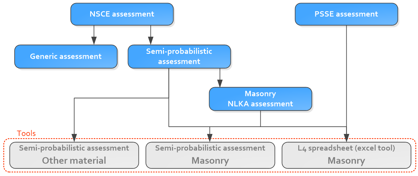
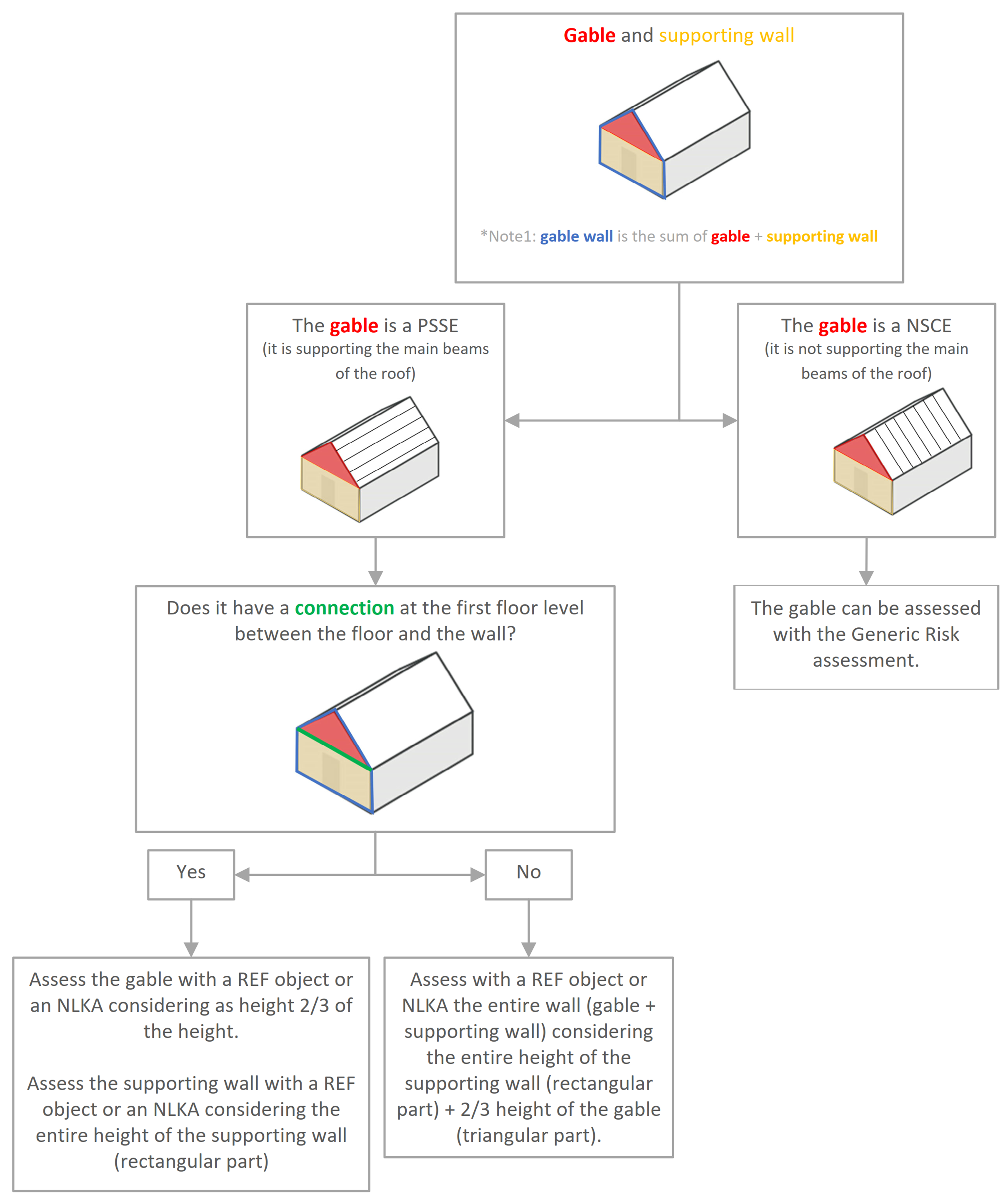
The following diagram demonstrates how to handle the assessment for the different elements and which tools are
available within VIIA.
Figure 128 Diagram of the NSCE and PSSE assessments and tools.
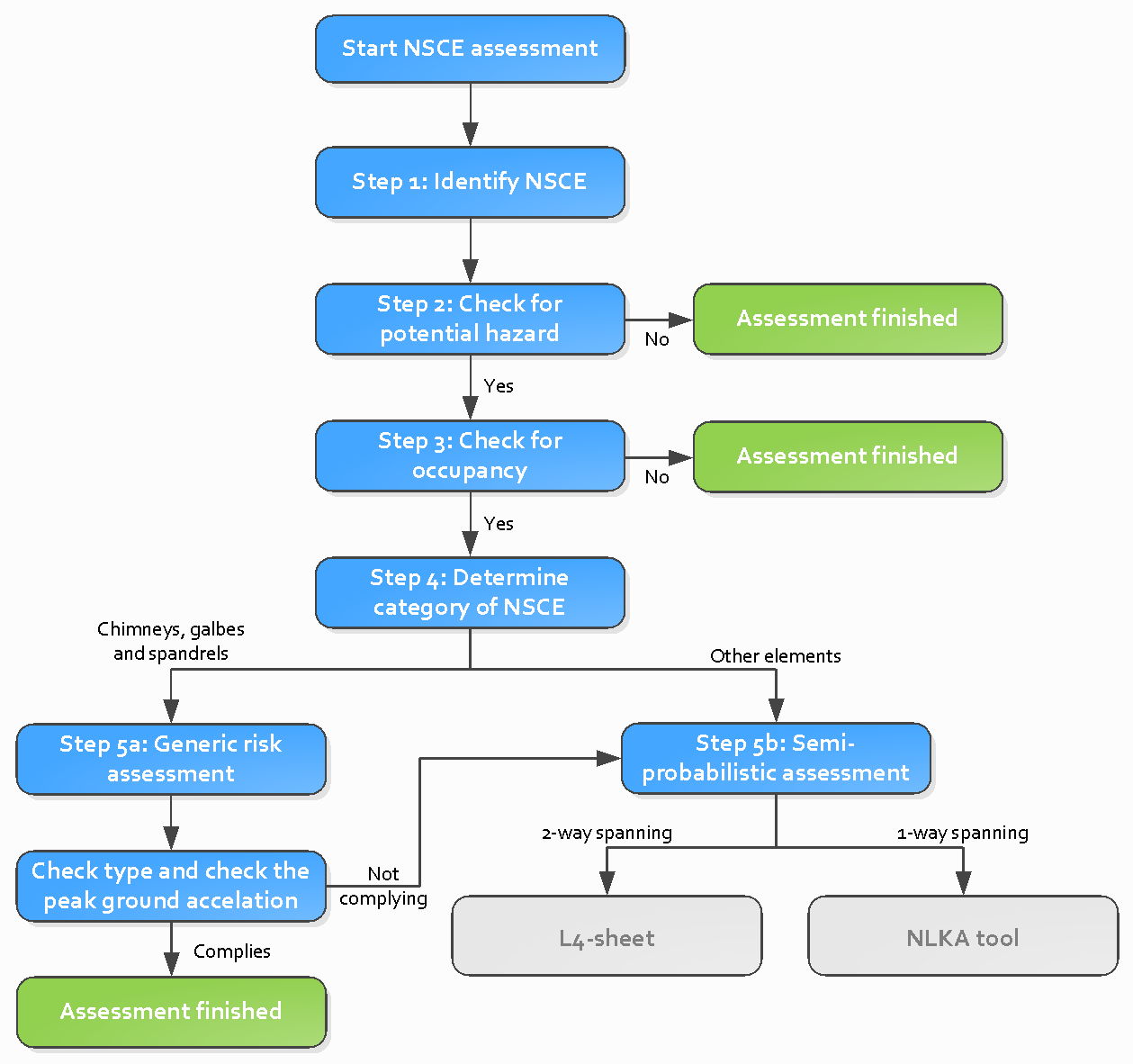
For NLTH and NLPO-SDF the workflow is the same for the NSCE. The workflow is shown in the figure underneath. The steps
are explained in this guide.
Figure 129 Workflow for the NSCE assessment in the VIIA project.
It is important to model the NSCE since as a strengthening measure a floor can be connected to a non-load bearing
wall, transforming it in a load bearing wall, thus it becomes a PSsE.
Also a non-load bearing wall can provide cantilever effect on the out-of-plane behaviour of a perpendicular wall
(1-way or 2-way bending) avoiding it’s failure.
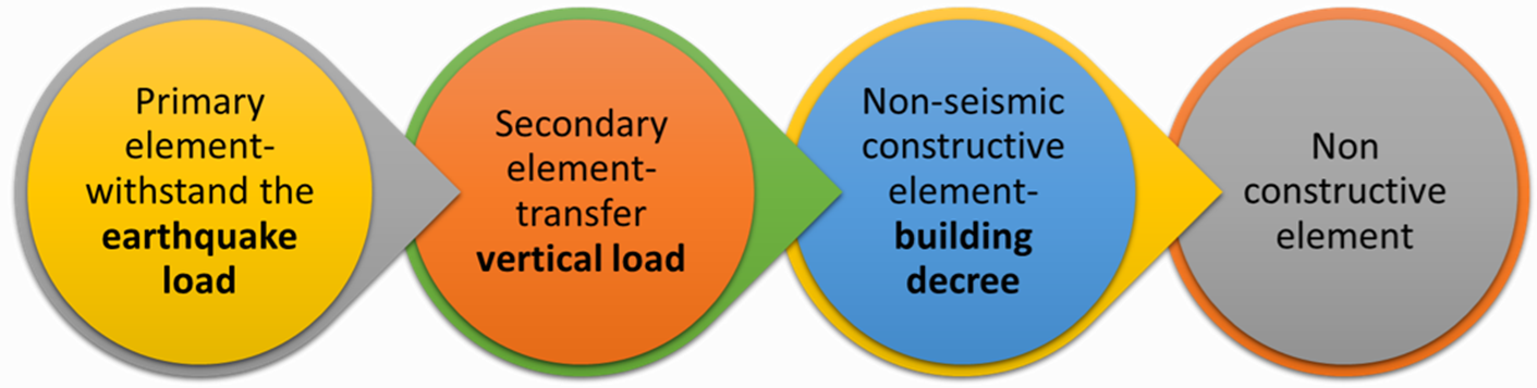
Within a building, elements can be categorised in following three groups according to the NPR:
PSSE: Primary and secondary seismic elements (Primaire and Secundaire Seismische Elementen)
NSCE: Non-seismic structural elements (Niet-Seismische Constructieve Elementen)
NCE: Non-structural elements (Niet-Constructieve Elementen)
A further explanation about PSSE, NSCE and NCE is given in the Basis of Design.
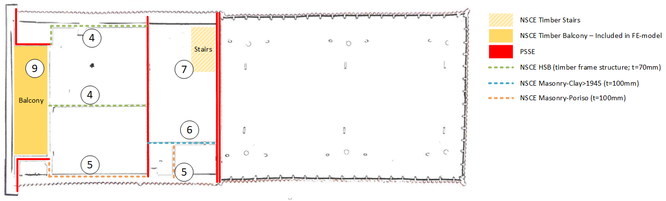
This step is to identify the non-seismic structural elements in the building. These are drawn on a floorplan of the
building. The colours are indicating the different element types of the NSCE’s. This drawing is part of Appendix C2. An
example of such a floorplan is given in Figure 3.
Refer to NPR 4.3.6.1 condition 1 to verify if there is any potential lethal hazard.
Non-seismic structural elements shall be considered if both the potential lethal hazard criteria and the occupancy
criteria apply:
Condition 1:
If the falling mass of the NSCE element or a part thereof is greater than 1 kg, and one of the following three
conditions is satisfied, the NSCE needs to be further assessed:
Vertical elements or parts thereof with a mass per area unit of less than 60 kg/m2 where the fall
height from the bottom of the element, or the part thereof, to the adjacent floor or the adjacent area
exceeds 2.0 m or the distance from the top of the element, or the part thereof, to the floor or the
adjacent area exceeds 3.0 m.
* Note that for a 100 mm thick masonry wall the mass per unit area is 200 kg/m2 .
Vertical elements or parts thereof with a mass per area unit equal to or greater than 60 kg/m2 where
the fall height from the top of the element, or the part thereof, to the adjacent floor or the adjacent
area exceeds 1.2 m.
Horizontal elements, if the mass per unit area exceeds 25 kg/m2 .
Condition 2:
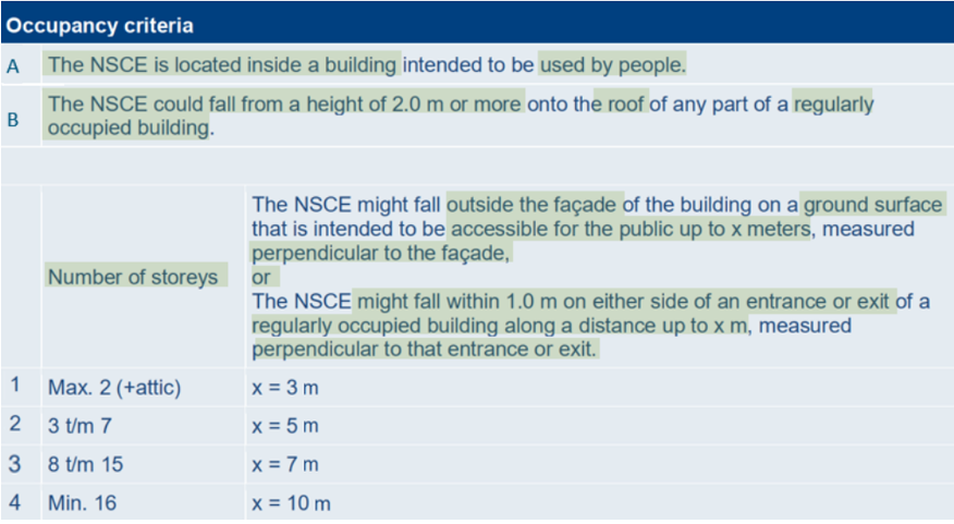
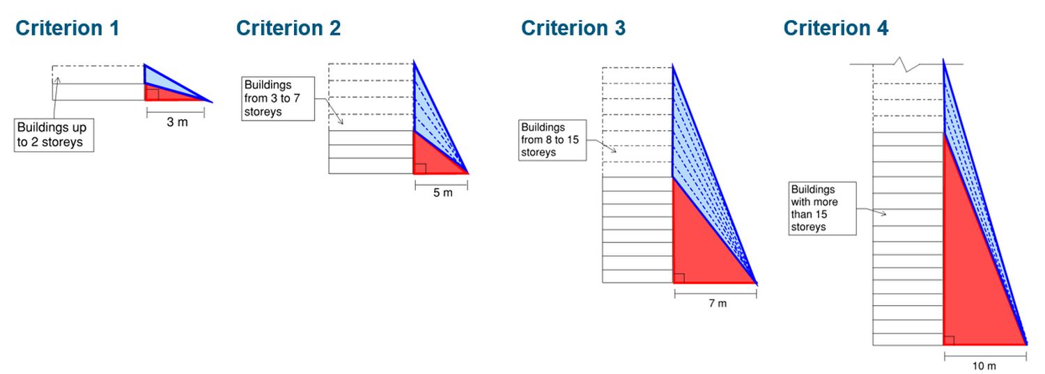
Refer to NPR 4.3.6.1 condition 2 to verify the occupancy at the location where the risk occurs: the element can fall in
a location where there is a significantly high probability of one or more people being present there during an
earthquake. An element complies with this condition if, in the event of full or partial collapse, every part of the
element, viewed in the horizontal cross section over the length of the element, might fall in or on points 1 to 4 of
the next table.
Some walls that might fall outside also might fall inside, thus criterion A of the following table is satisfied,
therefore there is no need to check criterion 1 to 4.
a ground plane projected perpendicularly for the falling element within 1 m on either side of an entrance or exit of
a regularly occupied building (measured horizontally parallel to the relevant façade) along a distance equal to the
provisions of a), measured perpendicular to that entrance or exit.
is located inside a building intended to be used by people, or could fall from a height of 2 m or more onto
the roof of any part of a regularly occupied building.
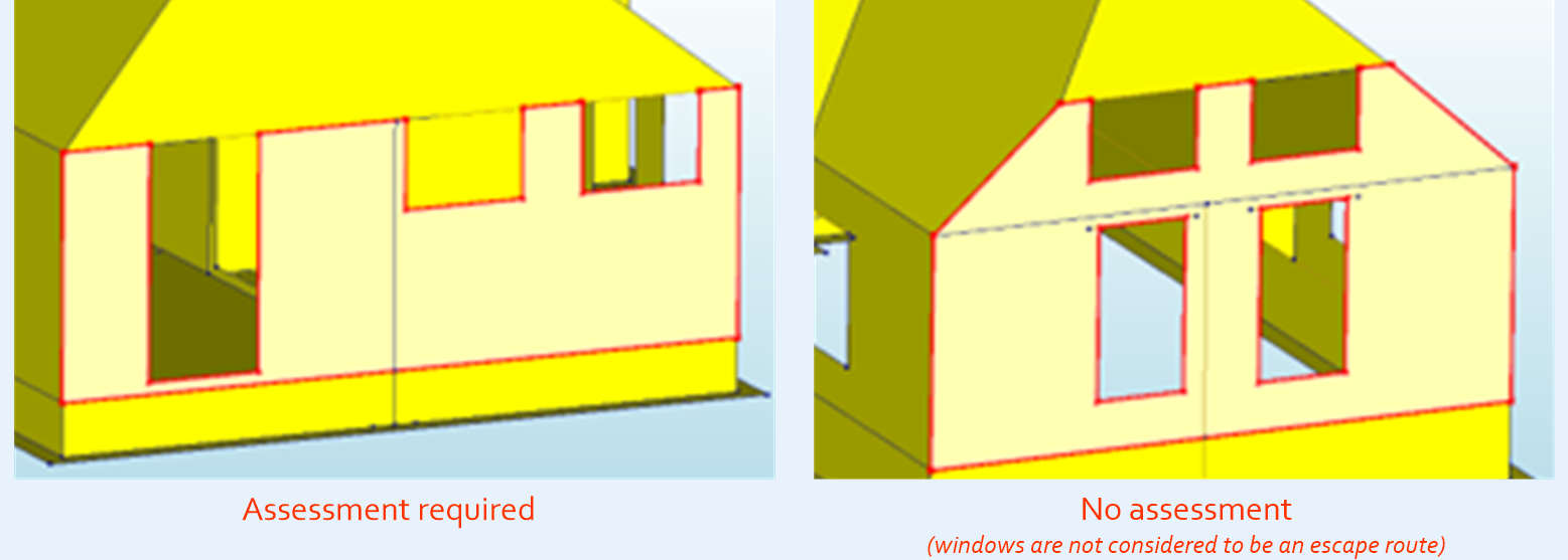
Note
If the failing element is falling into a space that is an escape route, assessment is required.
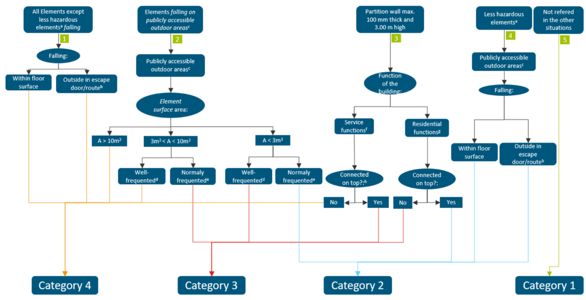
Refer to NPR table 2.2 to determine the category of the NSCE element.
The next flowchart presents different situations and the following paths which lead to choosing the adequate
category for the Non Structural Seismic Element.
Examples of less hazardous elements are: stairs in single family homes and glazing other than curtain walls.
Escape route or entrance area:
All doors, also doors to a garden/terrace + 1 m on both sides of them (defined as normally entrances and escape
routes used during fire);
Outdoor escape route: only if it is not possible to escape at about 2 to 3 meters distance from the building
(this includes pathways to escape from).
Publicly accessible outdoor areas: includes both situations:
Outdoor areas on the private property of the building which are open for public use by visitors to, or customers
of, facilities in the
Building such as restaurants, theatres or museums, and;
Outdoor areas on public property such as streets, squares, bicycle paths, or roads where people might be put
at risk by congregating outside or walking/cycling/driving past the building.
Note
Clarification of the criterion 1 to 4 of NPR 4.3.6.1 ‘Condition 2’ a):
Well-frequented: only sitting areas of bars/restaurants or similar and (reasonably busy) shopping
streets, ‘voetgangersgebied’ -> pedestrian area in city centers or similar. Streets where the cars pass usually
are not so crowded by pedestrians so are not included here.
Normally frequented: Other situations.
Service functions: Assembly** functions, healthcare functions, residential functions for 24/7 care,
education functions and comparable forms of use.
Residential functions: houses/apartments excluding residential functions for 24/7 care, lodging functions,
office functions and comparable forms of use.
Connected on top: A wall is considered well connected on top if the connection is reliable enough to resist
a seismic action, if this is true then YES applies, if not, is NO.
Note
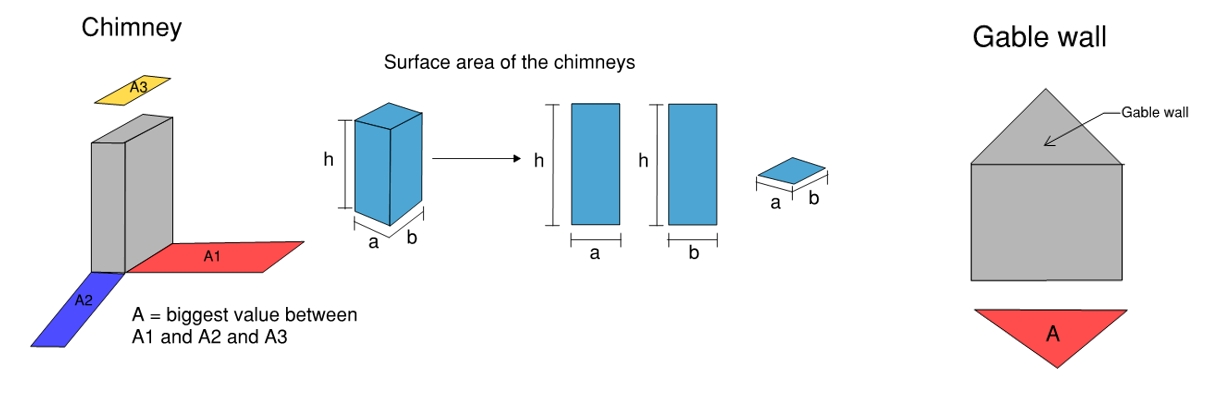
Clarification of the surface area of the element:
Area of the horizontal projection on a vertical plane or of the vertical projection on a horizontal plane of a
failing element.
Normally a chimney is assumed to roll of a roof and not fall through it.
During the earthquake, in case of sloping roofs, the chimneys are assumed to roll from the roof and not
to fall inside the floor area.
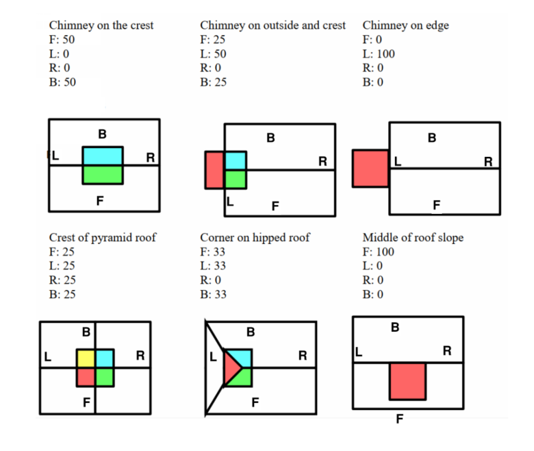
The following pictures show the probability of the chimney to fall in different locations of the building
depending on the type of roof.
For our TVA’s, these pictures are relevant to determine which areas should be considered to be are
at risk.
Figure 137 Scheme of the probability of the chimneys falling into certain areas due to their location in the roof.
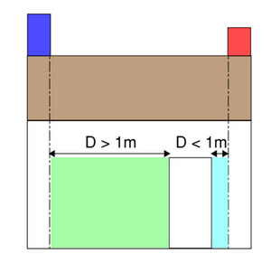
All chimneys are category 4 if they fall on an area as described below:
In the escape route (ingress or egress) or entrance area (the element, or part of it, can fall within 1m
of any part of the route). For example:
In the figure the red chimney would fall within less than 1 m next to the door so this chimney would be
-> Category 4;
On the other hand, the blue chimney would fall in a distance superior to 1 m regarding the access door,
thus would be checked, considering its area, and its location (well-frequented area vs normally frequented)
to determine its category.
It shall be considered that the gables are connected sufficiently to the upper element (roof, gutter, etc.). Therefore,
those will not be cantilevering. This is valid for single leaf walls as well as inner and outer leaves of the cavity
walls.
In order to choose the proper category, the surroundings around the falling area need to be assessed.
If the walls are falling inside the building, then should be -> Category 4
If they fall outside next to an escape route or pathways should be -> Category 4
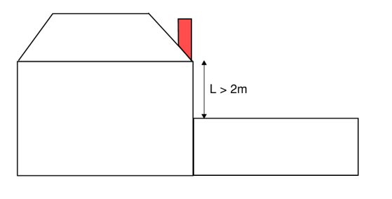
If the walls fall from a height superior to 2 m to another part of the building should be -> Category 4
If walls fall away from escape routes or pathways, then their category should be judged by their surface
area -> (Categories 4, 3 or 2)
The following workflow can be applied to the objects assessed.
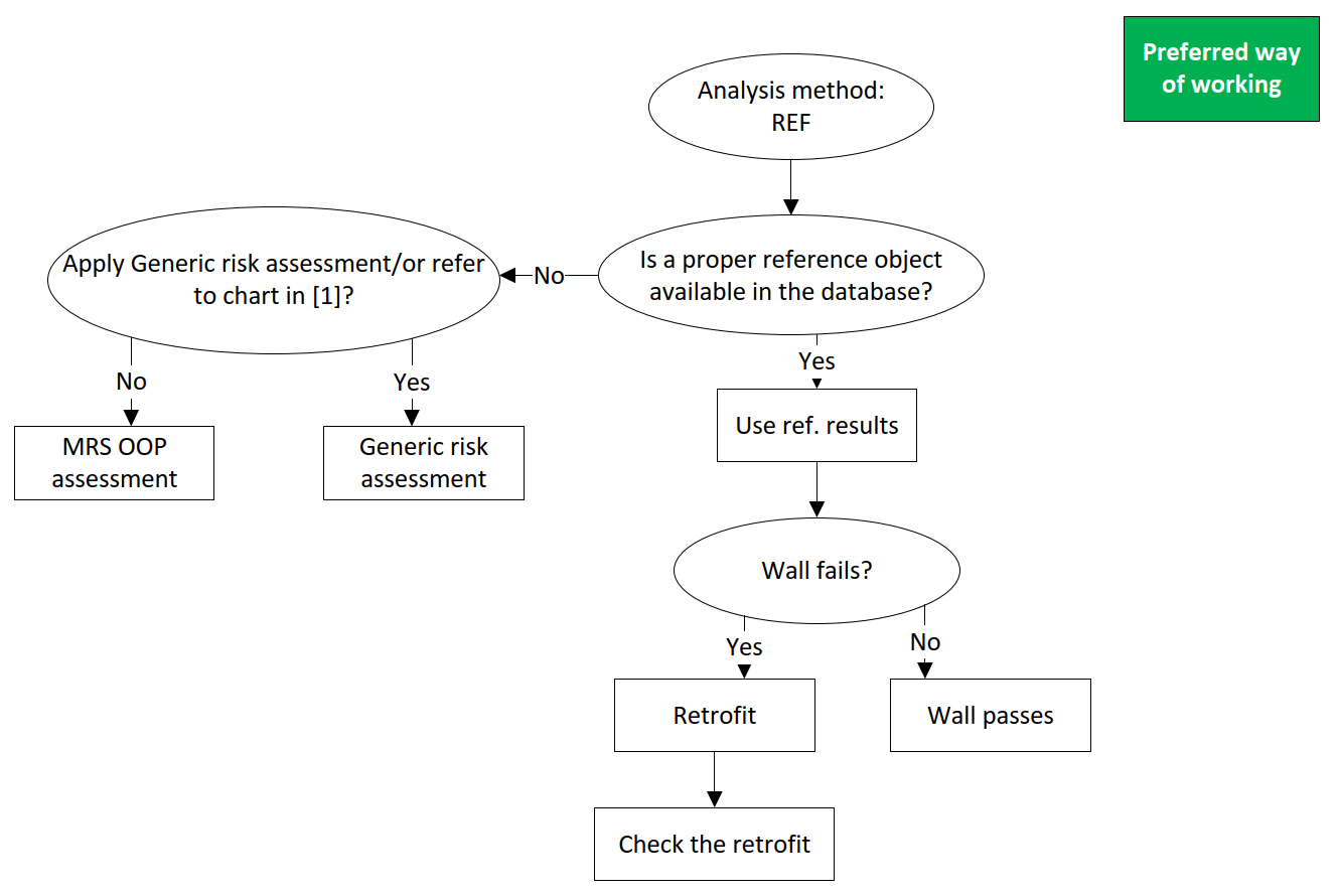
The cavity walls shall be assessed based on the analysis method: NLTH-REF/NLPO-REF, NLTH, and MRS/NLPO. There are two
flowcharts for each method, however, the flowcharts with ‘Preferred way of working’ label shall be applied by the
structural engineers. Please read the following paragraphs and terms in advance.
The upper boundary condition: It shall be considered that the outer leaves are connected sufficiently to the upper
element (roof, gutter, etc.). Therefore, those will not be cantilevering.
OOP Assessment: The term refers more in general to the NLKA/virtual work method using the L4 tool. It is expected
that the engineer knows how to perform the assessment, how to perform the 1-way or 2-way spanning depending on the
particular case. In order to decrease the computation time, a good practice is to start with the 1-way spanning
assessment, and eventually proceed with the 2-way spanning assessment if necessary. When all the possible situations
that represent the wall analysed have been performed, the assessment can be considered concluded.
Retrofit: The term refers in general to the right measure for the case, based on the GMC database. Retrofit is
intended as the more cost-effective measure that can prevent failure of the element. In order, the retrofitting measures
to apply are assumed: connections (top and/or bottom), cavity wall ties, out-of-plane measures (L4 measure).
Check of the retrofit: Each proposed measure has to be explained and the results verified. If for example the first
assessment of a cavity wall without ties leads to failure, cavity ties are the first measure to be proposed. If the
assessment of the retrofitted wall fails again, a further measure has to be proposed (and verified).
Figure 140 Flowchart preferred way of working for NLTH-REF and NLPO-REF.
Refer to document VIIA_QE_R2037.
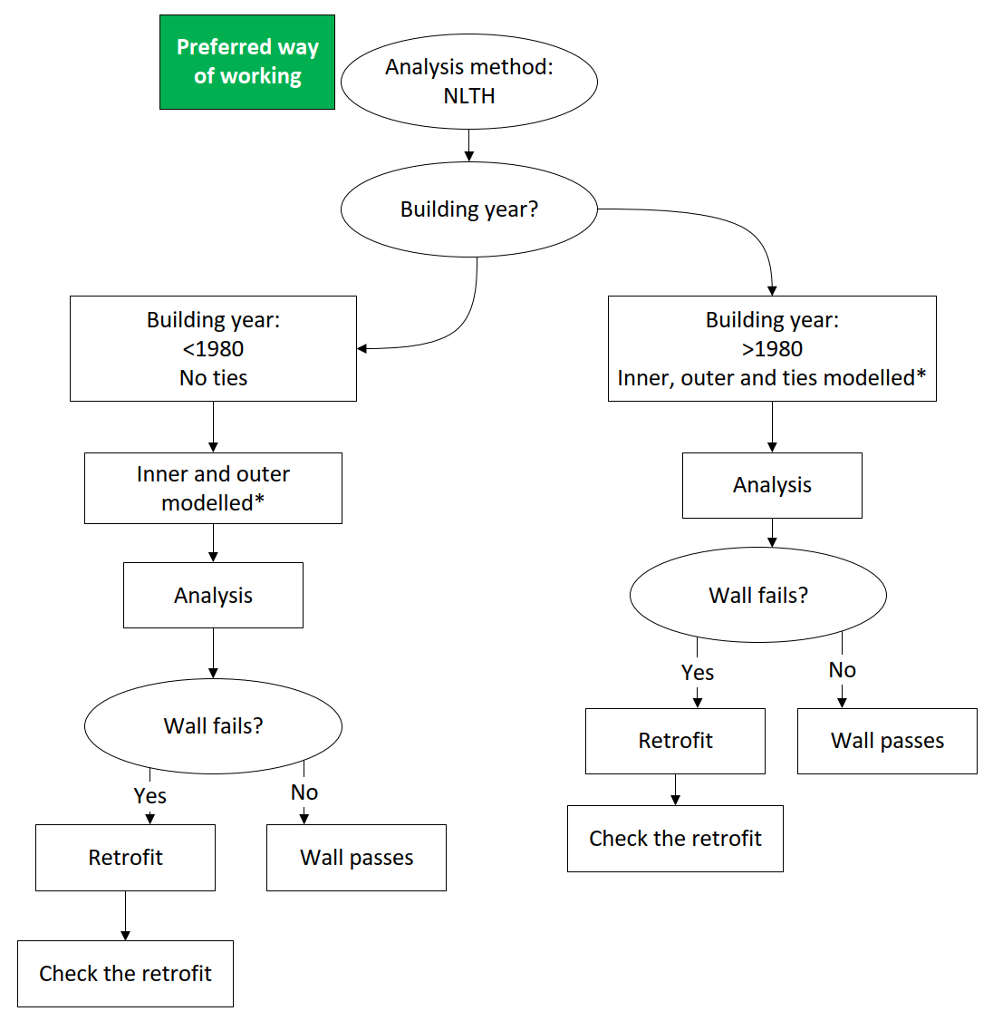
Figure 141 Flowchart preferred way of working for NLTH.
Modelling in DIANA:
To connect the outer to the inner leaf, in DIANA two approaches can be followed:
Model a roof plate at the top of the element and a D2.01 line interface.
Create a dummy plate between inner and outer leaf (not recommended, due to the local axes).
Modelling in ABAQUS:
In ABAQUS ties should be modelled explicitly.
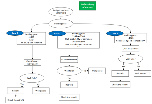
Figure 142 Flowchart preferred way of working for MRS or NLPO.
** The NLTH results for a 2-storey building showed that cavity walls with 2 ties/m2(considered case of high
possibility of corrosion) and 4 ties/m2(in general >1990) possessed comparable capacity. It is considered
that this conclusion also holds for cavity ties 1.67 ties /m2as per section 9.2 of NCG-ABSC version 1.2. In
case of less cavity ties or highly corroded cavities ties, it is recommended to apply measure L4-D.
*** Measure L2-051 (renovation anchor) at floor level, if ties are already present, is generally not necessary.
The outer leaf can be included in the determination of the resistance of the cavity wall if all the following the
conditions are met:
It has been proven that sufficient reliable cavity ties are present;
It has been proven that sufficient reliable cavity-ties or anchors (or another connection) are present at the level of
the diaphragm (roof or floor) to connect the outer leaf to the diaphragm as a horizontal support.
If anchors are used, it should be verified whether sufficient displacement capacity is available to cope with thermal
movements.
Use the proper version of the L4-sheet in order to take into account the contribution of the outer leaf to the seismic
capacity of the wall.
The category of the non-load bearing outer leaves in a cavity wall can be determined as follows:
If the walls are inside the building, they should be -> Assessed as partition walls;
If walls fall outside next to an escape route or pathways -> Category 4;
If they fall from a height superior to 2.0 m to another part of the building -> Category 4;
If they fall away from escape routes or pathways, then their category should be judged by their surface area ->
**Categories 4, 3 or 2.
For chimneys, spandrels and gable walls, the generic risk assessment can be performed. Refer to NPR9998:2018 appendix J.
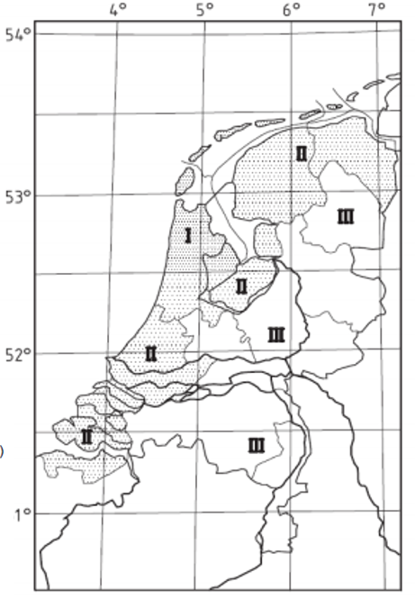
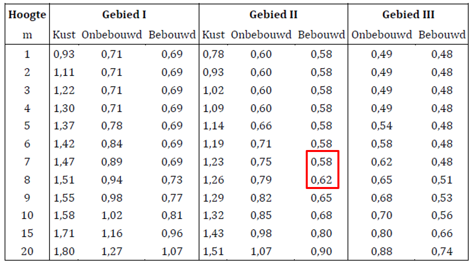
Occurring PGA (‘demand’):
Choose the agS (g) corresponding to 475 years for the specific location (Webtool)* .
Maximum allowable PGA (‘resistance’):
Determine the member type;
Determine the category;
Go to Table 1 in the Protocol (How to perform NSCE and NLKA checks) or Table 9-10 UPR 05/2021;
Get the value of agS (g) corresponding to the NSCE category and Type.
Occurring PGA < Maximum allowable PGA -> OK
Occurring PGA > Maximum allowable PGA -> FAIL proceed with Semi-probabilistic assessment
Table 1 gives the maximum PGA allowed for a certain element.
Table 1 - Maximum peak ground accelerations in [g] for chimneys, spandrels and gable walls.
Type of NSCE \ NSCE Category
2
3
4
Chimneys and parapets, freestanding walls and balustrades pre 1920
0.149
0.114
0.078
Chimneys and parapets, freestanding walls and balustrades from 1920 onward
0.207
0.164
0.118
Gables, pre 1920
0.283
0.248
0.203
Gables, from 1920 onward
0.298
0.263
0.217
* Check the peak ground acceleration ag S for the location of the building on the
webtool. If the value in the table is higher, the element complies.
Attention
Please the use the ag S of the 475 return period from webtool to compare with the capacity of
the corresponding return period of the NSCE category.
Example:
When you have a gable built in 1930, which is category 4 NSCE element, according to
Step 4 the return period is 2475 year, then the capacity you get from
the table is 0.217 g. Then you check the webtool for the 475 return period ag S for the
assessment, if the ag S is lower than 0.217 g, then this element complies.
Tool for the semi-probabilistic assessment for other materials: Tool
Warning
The tool for other material is currently available in the teams channel for NSCE and NLKA. They still
need validation by the knowledge team or will be later updated on the assessment method from knowledge team.
For existent buildings, the application of conservative code requirements (elastic domain) required for new building may
turn into expensive retrofitting solutions, this has been observed in earlier modal analysis assessments with
out-of-plane (OOP) seismic actions calculated from the linear elastic analysis (LEA). The seismic resistance based on
stability mechanisms rather than static strength, where a cracked URM wall is modeled as rocking rigid blocks, is less
conservative and closer to the actual behaviour of unreinforced masonry. A kinematic approach is proposed in the NPR.
The NLKA assessment (Non-Linear Kinematics Analysis) is used to determine the out-of-plane behaviour of unreinforced
masonry elements (walls, gables, etc).
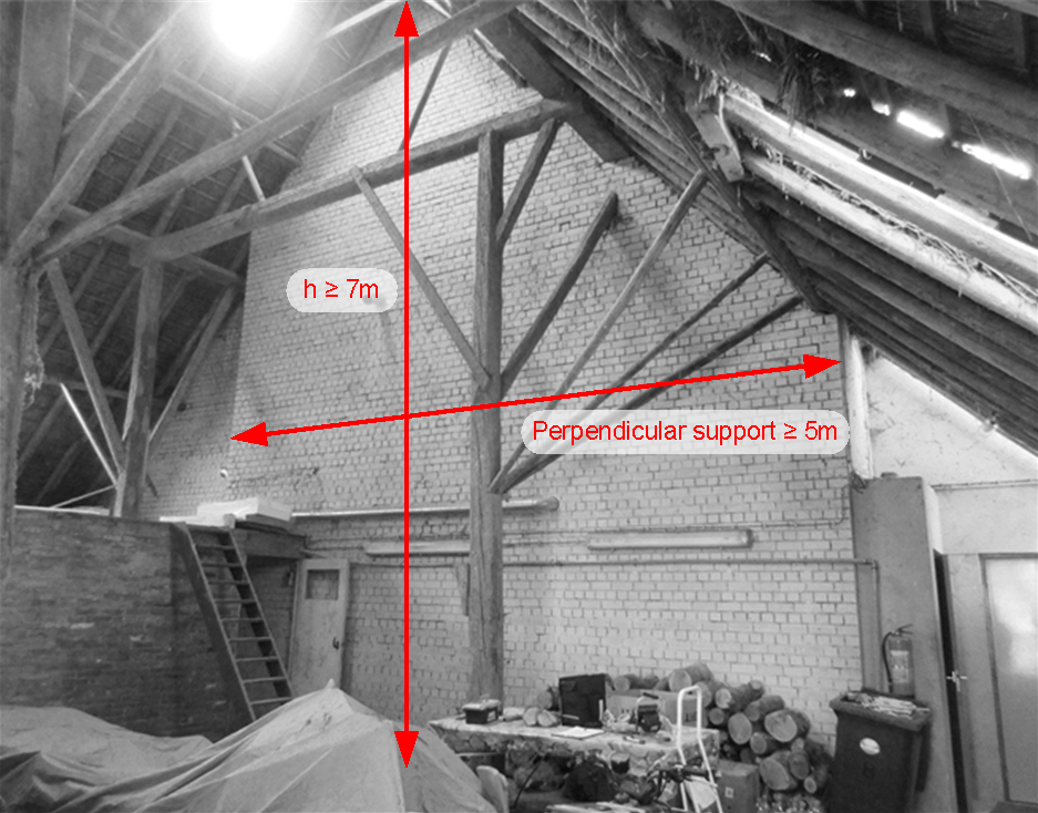
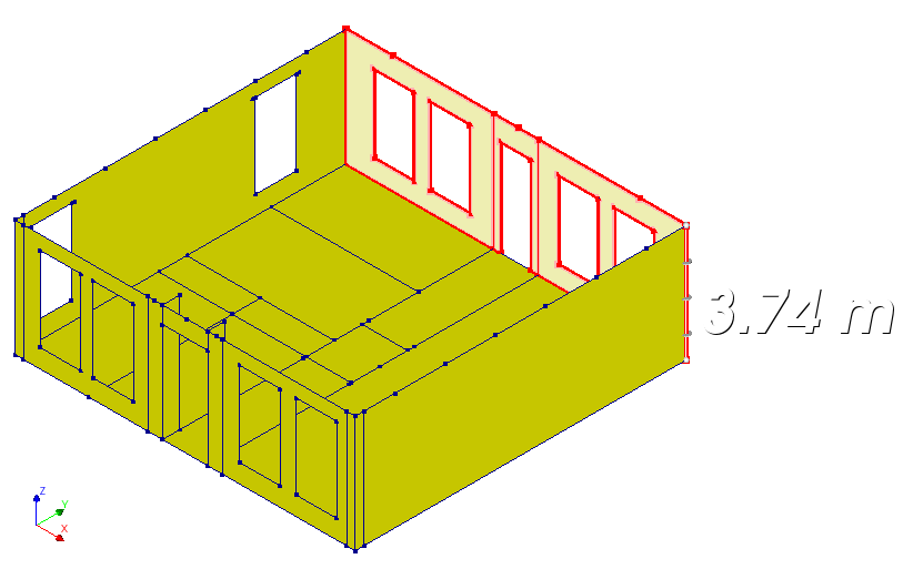
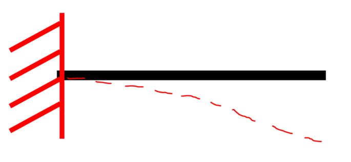
The upper connection of the walls that are classified as ‘high’ (h_wall≥7m and distance to the perpendicular support ≥
5m) shall be checked carefully. If the wall is connected sufficiently to the upper element, the NLKA method can be
applied otherwise; an L2 measure shall be used at the top. Afterward, the NLKA method can be applied. The following
figure shows an example of a ‘high’ wall.
Regarding the cavity walls, the floors and the cavity wall ties determine the height of the inner and the outer leaves.
If the timber/concrete floor is not resting on the outer leaf and the outer leaf is not connected to the inner leaf with
ties/anchors, it spans the whole height. Otherwise, it spans from floor to floor.
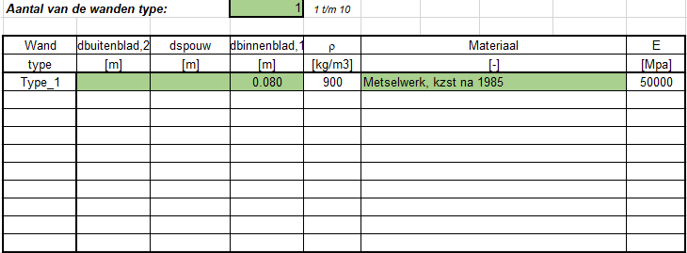
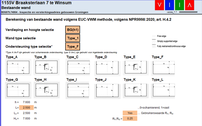
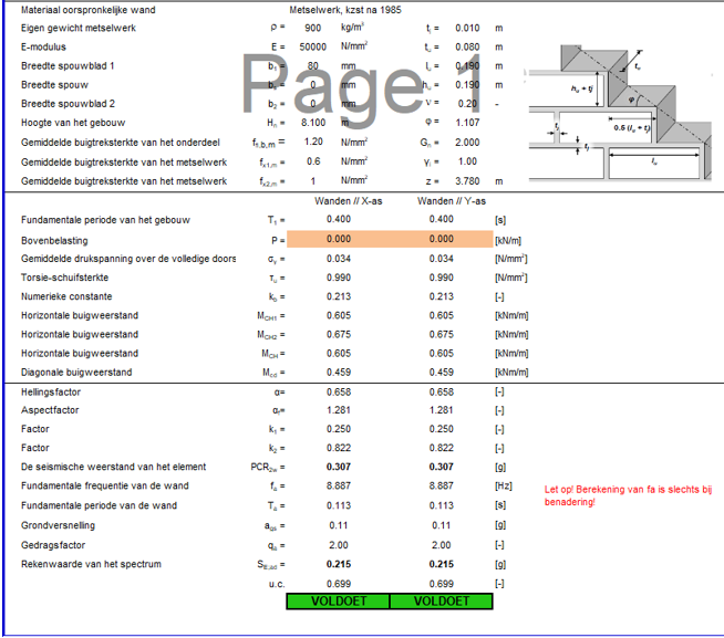
The tool used to perform the NLKA analysis on masonry elements is the Excel Tool: L4 spreadsheet. For application with
NPR9998:2018+C1+A1:2020 you should use version 6.9 of the tool (
LINK NPR2018_v6.9)
. For application with NPR9998:2020 you should use version 7.7 of the tool (
LINK NPR2020_v7.7)
or version 8.0 (
LINK NPR2020 v8.0).
If the non-load bearing
leaf contributes to the seismic capacity of the load bearing leaf, the last version of the tool shall be used.
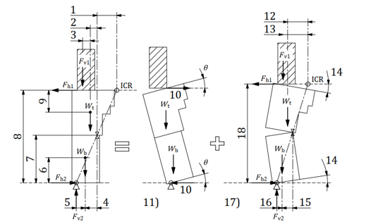
In the case of one-way spanning unreinforced masonry walls the out-of-plane seismic demand could be obtained by using
the NLKA method. This demand together with the resistance of the wall can be used to derive the maximum allowed height
of a wall by checking for which height the unity check will be equal to 1 (or just below 1). This can be done
repeatedly for different sets of parameter combinations after which it can be visualised with a graph showing curves for
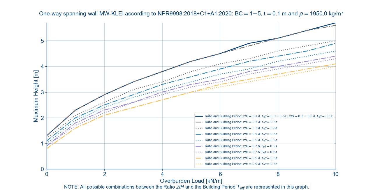
these different combinations of parameters. The curves on the graph show a maximum wall height versus the overburden
load for specific boundary conditions. Each individual curve represents a specific combination of generalized values
for the center of gravity over height ratio (z/H) and the building period (Teff). The figure below gives an
example of such a graph.
Figure 145 Maximum heights one-way spanning wall for boundary conditions 1-5
The graph needs some explanation in order to understand it and for it to be of use to the engineer. The data points in
any of the curves shown in the graph represent the maximum height of a wall under a certain overburden load, z/H ratio
and Teff for which the wall still complies to the seismic demand. It should be noted that the boundary
conditions of the wall, for example BC 1 and 5, also have an impact on the seismic demand and therefore the curves.
However, the BC’s are always the same for all curves on the graph. If the engineer observes a wall in their building
that for the applicable parameters would represent a data point above the corresponding curve, this would represent a
failure of the wall for the out-of-plane assessment.
In some cases, combinations of the parameters z/H and Teff yield the same result for the maximum heights.
For this reason only one curve is plotted in the graph instead of multiple. The different combinations of z/H and
Teff that lead to the curve are combined in a range of values that is shown in the legend for that particular
curve. All graphs are ‘cut-off’ at a 8.0 m height of the wall if applicable. It is assumed that in reality most walls
are not higher than 8.0 m, thus making the results with maximum wall heights above this value irrelevant. Therefore,
curves that are completely above the 8.0 m cut-off are not plotted. Instead the note beneath the graph will inform the
engineer about the parameter combination(s) that produce(s) a curve that is not plotted.
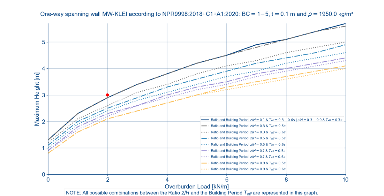
Example: Take the curve from the first entry in the legend of Figure 18. If the z/H ratio is 0.1 and the
Teff is in the range of 0.3 s to 0.6 s or if the z/H ratio is in the range of 0.3 to 0.9 and the
Teff is 0.3 s, the dark blue curve is the result for the maximum allowed heights. If, for example, a wall in
your building is 3 m high, has an overburden load of 2 kN/m, a z/H ratio of 0.5 and a Teff of 0.3 s, the data
point that would represent this input would lie above the dark blue solid curve. Therefore, the engineer can directly
conclude that there is failure in this wall. See figure below for the visualization with the red dot representing the
data point described above.
Figure 146 Out-of-plane failure of wall if data point, represented by the red dot, is above the applicable curve.
The goal of these location specific capacity graphs is to preemptively assess whether certain unreinforced masonry walls
in a building are going to fail out-of-plane. If so, the engineer can choose, in consultation with the lead engineer,
to apply pre-measures to the wall. This can save analysis time and speed up the assessment process.
The graphs will be generated automatically when creating the project. This is done only once to save runtime in later
use of your modelscript or mainscript. All the necessary graphs will be generated, but if desired it is possible
to generate (an) additional graph(s). This can be done by using the
_viia_nlka_graph_data() function with the parameters the engineer desires.
Note: Both the the z_over_height and
building_period function arguments could be
asigned as a singular value but should be provided in the format of a list containing that value.
Several third-party packages are needed for this tool to work, they are as follows:
MatplotlibPyQt5**|
**fpdf
Please make sure you pip installed these packages before you use this tool.
You can find template_NLKAscript.py in the folder of templates in viiapackage. Please save a copy of this python
file in your work folder. Afterwards please change the object name without “-model” at the end. Only in this way can the
data from database be retrieved as inputs for NLKA tool.
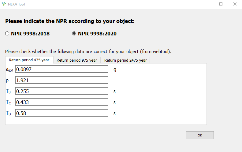
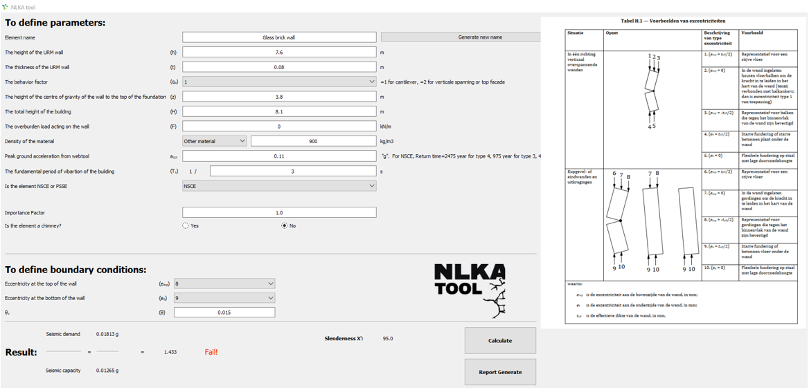
Now if you run this script, you will see the window below popping up on your screen.
Because currently there are objects using the NPR9998:2018 and the NPR9998+C1+A1:2020 , you need to choose between this
two options. Confirm this with your project leader if you are not sure.
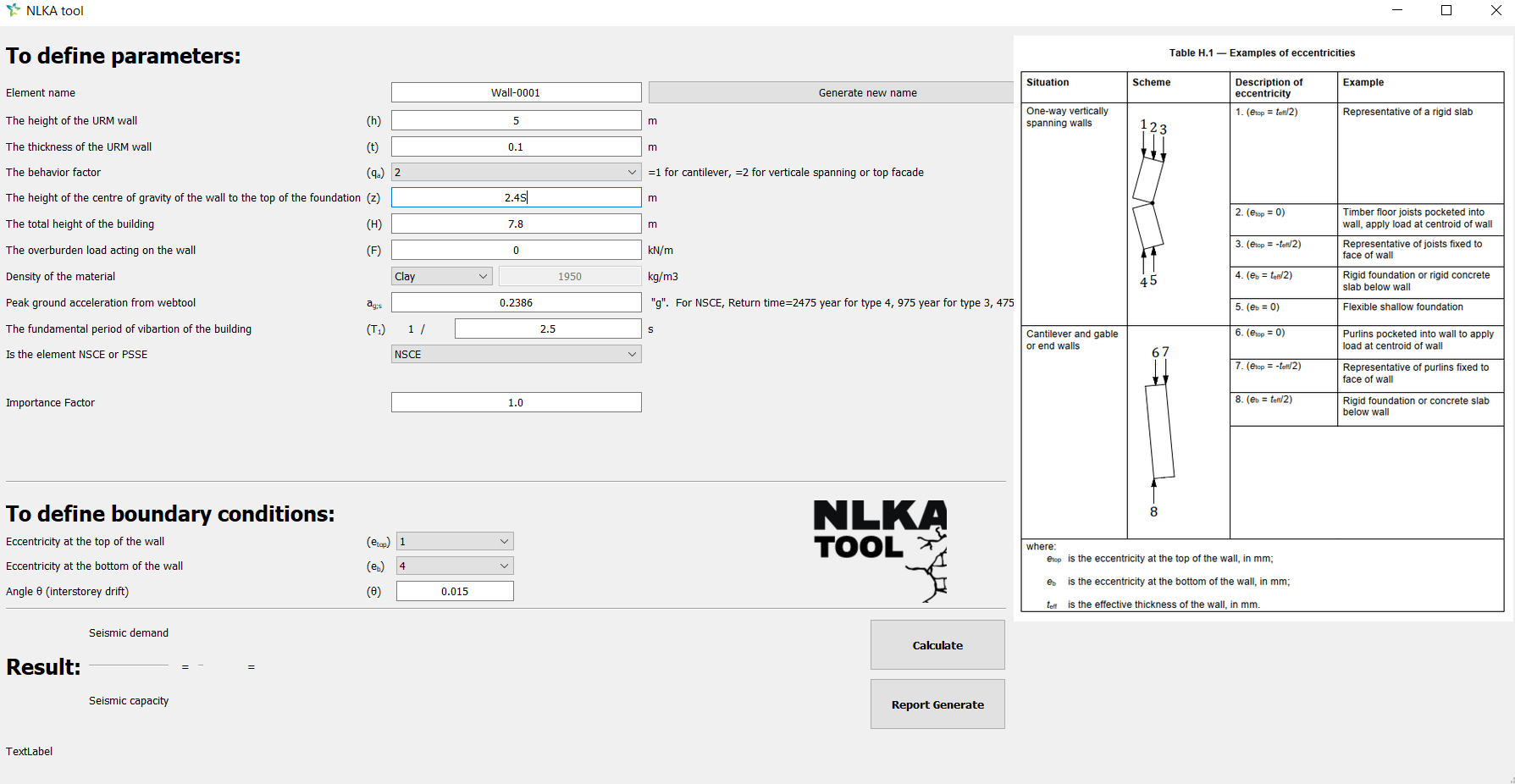
Once you select and click OK button, you can see the following window pops up. The options for boundary conditions and
the picture for table H.1 will be different if the NPR9998+C1+A1:2020 is selected.
Element with numbering at its end, by clicking Generate new name a new name will be generated, be careful that by
using the same name the report of the same element name will be replaced.
The height of the URM wall
The height of the masonry element. If you have question about the height of triangle wall, please check the
question of triangle wall.
The thickness of the URM wall
The thickness of the element. If you have question about the cavity wall, please check the
question of cavity wall.
The behavior factor
The element behaviour factor, qa = 1 for cantilevers and qa = 2 for vertical spans and gables. If you have question
about cantilever element, please check the
question of wall not in the spanning direction.
The height of the centre of gravity of the wall to the top of the foundation
As is stated.
The total height of the building
The height of the building above top of the foundation or rigid basement
The overburden load acting on the wall
The overburden load acting on the wall per meter.
Density of the material
As is stated.
Peak ground acceleration from webtool
As is stated. Check the peak ground acceleration a g S for the location of the building on the
webtool.
The fundamental period of the vibration of the building
As is stated. If you have question about the frequency of the building, please check the
question of frequency.
Is the element NSCE or PSSE
As is stated. When NSCE is selected, the importance factor will always be set at 1.0. When PSSE is selected,
You have to give the consequence class of the object so that the right importance factor will be used to multiplied
Note
In Table 2.4 of the NPR is mentioned that for elements of category 4, that fall from a relatively great
height onto an adjoining roof under which there can be people, the importance factor should be 1.2.
Consequence Class
As is stated. You can check the consequence class of your object from MYVIIA or consult with your project manager.
Is the element a chimney?
As is stated. If yes is selected, the overburden load row will be switched to zero, this option is only shown if
the Cantilever behavior factor is selected.
Explanations for boundary conditions are as follows:
Eccentricity at the top of the wall
For NPR9998:2018, 1, 2 or 3 can be selected if behavior factor 2 is selected, 6 or 7 can be selected if behavior
factor 1 is selected, please check table H.1 for more explanation.
For NPR9998+C1+A1:2020, 1, 2 or 3 can be selected if behavior factor 2 is selected, 6, 7 or 8 can be selected if
behavior factor 1 is selected, please check table H.1 for more explanation.
Eccentricity at the bottom of the wall
For NPR9998:2018, 4 or 5 can be selected if behavior factor 2 is selected, 8 can be selected if behavior factor 1
is selected, please check table H.1 for more explanation.
For NPR9998+C1+A1:2020, 4 or 5 can be selected if behavior factor 2 is selected, 9 can be selected if behavior
factor 1 is selected, please check table H.1 for more explanation.
Angle θ (interstorey drift)
The inclination angle of the element. For the NPR9998+C1+A1:2020, θ v is shown here. θ v in
NPR9998+C1+A1:2020 corresponds to θ in appendix H of NPR9998:2018. If you have question about the inclination angle,
please check the question of inclination angle.
How to select proper boundary conditions for your elements:
As per Table H.1 there are two possible schemes for wall element -
One-way vertically spanning walls
Cantilever or Gable or End walls
One-way vertically spanning walls
There are three possibilities for eccentricity at the top - 1, 2, and 3.
Boundary condition 1 is used if there’s a rigid floor resting on top of the wall.
Boundary condition 2 is used if there is a timber floor resting on the wall and the floor beams of the timber
floor are transferring loads at the center of the wall cross section.
Boundary condition 3 is used, if floor joists are fixed to the face of wall (this is the case when the wall-floor
intersection is parallel to the floor spanning direction) and are not embedded in the wall.
There are two possibilities for boundary condition at the bottom - 4 and 5
Boundary condition 4 is used if there is a rigid concrete foundation or a rigid slab located below the wall. The
boundary condition 5 is used conservatively if a shallow (masonry footing) is present below the wall.
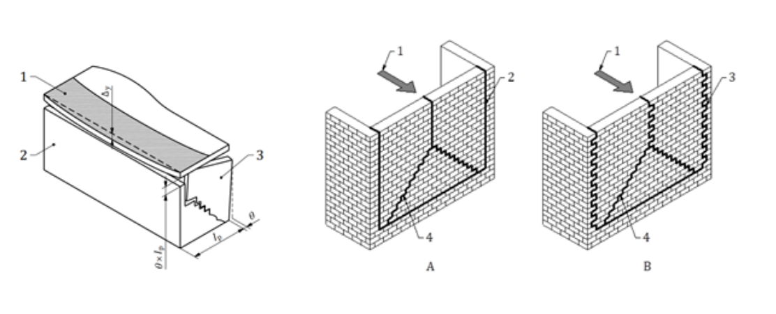
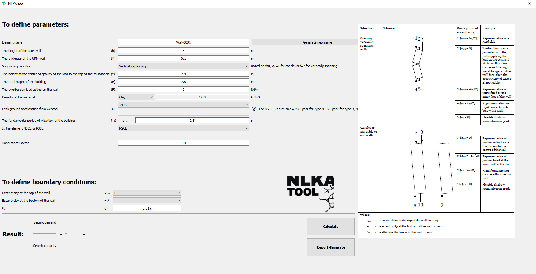
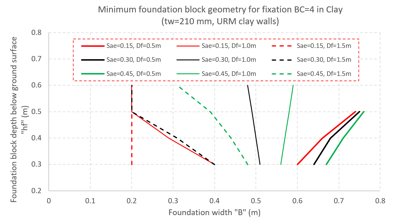
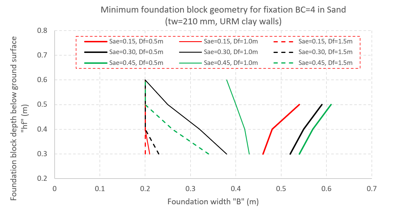
Boundary condition 4 may be used also for masonry strip footings when a minimum foundation geometry is observed (footing
width ‘B’ and block height ‘hf’). To determine the minimum geometries for clay like soil and sand like soils and walls
of 100 mm and 210 mm of thickness use the following 3 images. Notice that for 100 mm clay brick walls in sand likesoils BC=4 can be directly assumed. The seismic intensity ‘Sae’ corresponds to the value of ‘SEa;d’ as defined in
the NPR section H.3.1.
Figure 150 Minimum foundation block geometry for fixation in clay like soils and 100 mm clay brick walls
(Sae=seismic intensity).
Figure 151 Minimum foundation block geometry for fixation in clay like soils and 210 mm clay brick walls
(Sae=seismic intensity).
Figure 152 Minimum foundation block geometry for fixation in sand like soils and 210 mm clay brick walls
(Sae=seismic intensity).
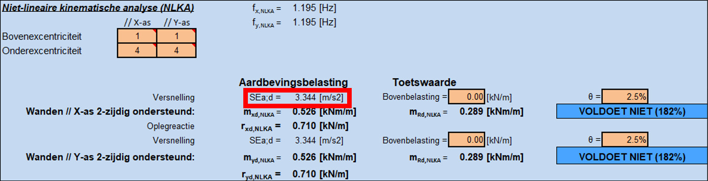
‘Sae’ can be extracted from the L4-sheet alternatively (SEa;d in the sheet). Please consider that the extracted
intensity shall be divided by 10. Therefore, from the following results, 0.3344 [g] must be used, for instance.
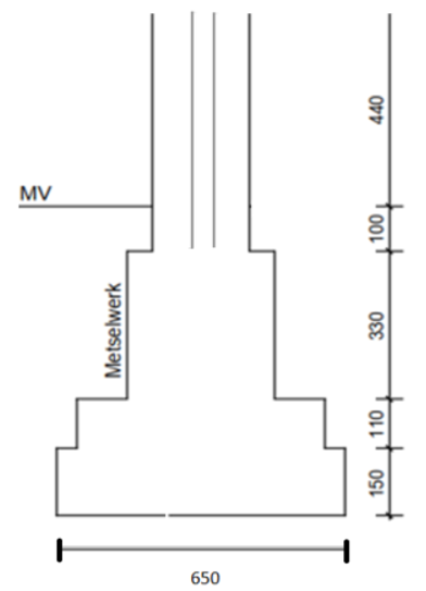
100 mm clay brick walls graphs shall be used for cavity walls. However, for calculating ‘B’, both leaves must be taken
into account. See the following example in which the outer leaf is assessed.
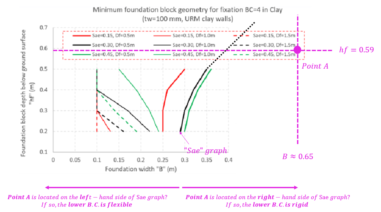
B (650 mm), hf (590 mm), and Df (690 mm) can be found from the figure and Sae (0.27 [g]) from the L4-sheet. For this
case we can use the thicker solid black graph: Sae=0.3, Df=0.5m.
Firstly, find the intersection of “B” and “hf’ as follows: Point A. Then extend the Sae graph by extrapolating ‘B’ and
‘hf’ (dotted line in the following figure). If Point A is located on the right-hand side of the Sae graph, choose rigid
boundary condition for the outer leaf of the cavity wall. See the following figure.
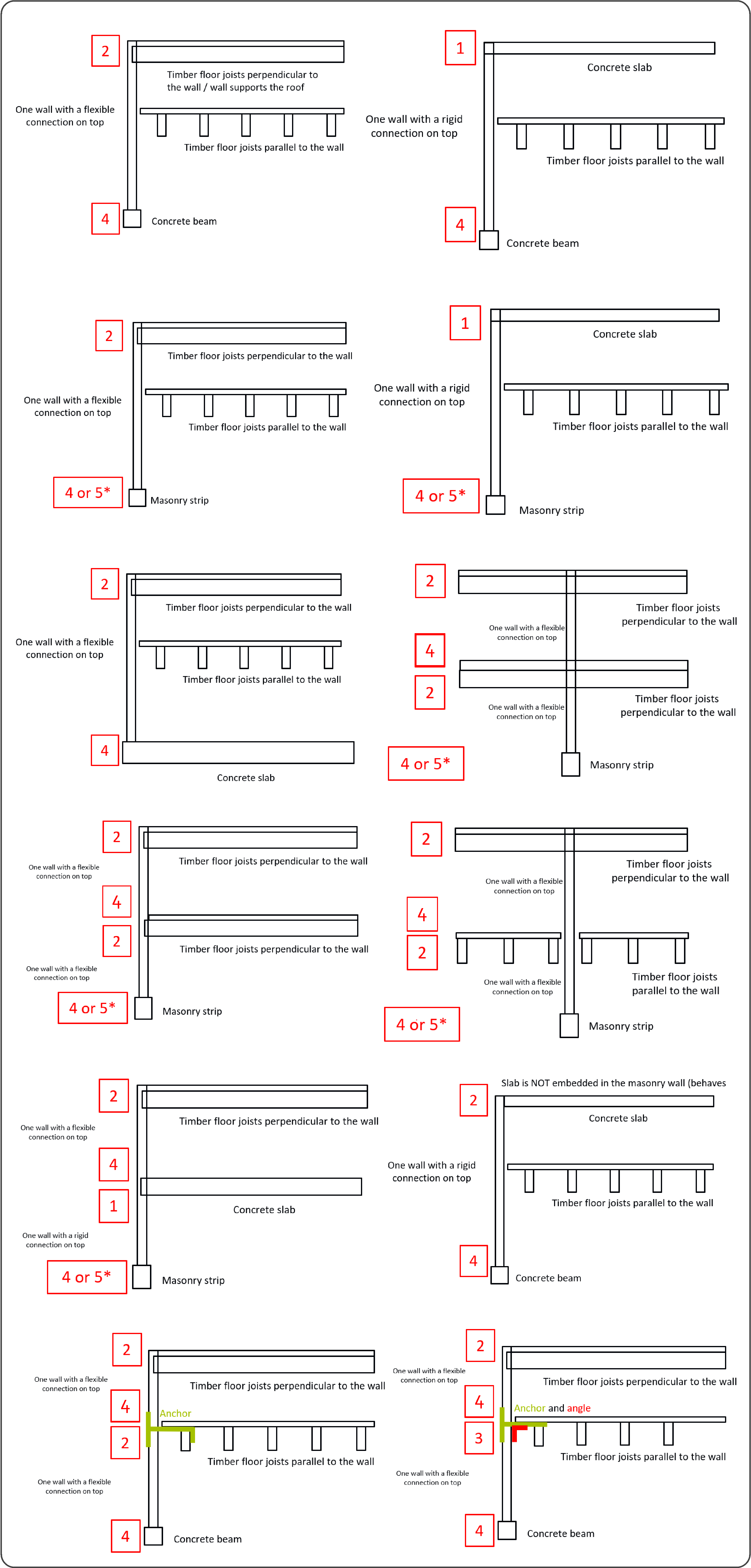
Some examples are provided to assist in the selection of the boundary conditions:
Figure 153 Example selection of boundary conditions (Check the minimum foundation block geometry graphs to
identify if it is 4 or 5).
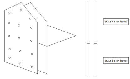
Whenever in presence of a cavity wall with ties, with outer leaf spanning two storeys, it has been demonstrated that
the wall can be split at floor level. The boundary conditions for both cases and both leaves are B.C. 2 at the top and
4 at the bottom.
Figure 154 Example of cavity wall with ties, with outer leaf spanning two storeys.
Cantilever and gable or end walls (As per NPR 9998: 2018)
There are two possibilities for eccentricity at the top - 6, and 7.
Boundary condition 6 is used, when the roof purlins are pocketed into the wall and load is applied at the center
of the wall cross section.
There is only one possibility for eccentricity at the bottom - 8.
Boundary condition 7 is used when purlins are fixed to the face of the wall (this is the case when wall-roof
intersection is parallel to the roof spanning direction) and are not embedded in the wall.
Cantilever and gable or end walls (As per NPR 9998: 2020)
There are two possibilities for eccentricity at the top - 7 and 8.
Boundary condition 7 is used if there are purlins embedded in the wall such that they transfer vertical loads
from roof on to the center of wall.
Boundary condition 8 is used if there are purlins attached to the face of wall and is not embedded into the
wall.
There are two possibilities for eccentricity at the bottom - 9 and 10.
Boundary condition 9 is used if there is a rigid foundation or concrete floor under the wall.
Boundary condition 10 is used if there is a shallow foundation under the wall.
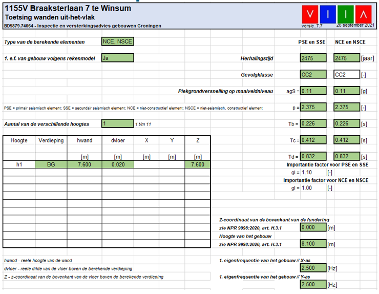
After you fill in all the needed inputs, you can press the button Calculate to see the result. If you would like to
check the results, you can press Report Generate to create the pdf report, the report and the graph will be create
in the folder of the element name, which is inside the NSCE Assessment folder of your work folder.
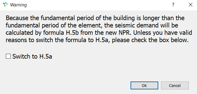
Attention
When using the tool according to the NPR9998+C1+A1:2020, it is possible that you will get a warning when
the calculated element period is shorter than the fundamental period of the building. In that case you
are not sure if you can switch to formula H5.a in the the new NPR in this case, please consult with your
lead engineer.
This chapter includes the questions from all the team members, if you have doubts during the NSCE or NLKA
assessment, please send your question to taskforces, they will communicate with the knowledge team.
1.1 - The θ used for outer leaf or other NSCE elements – How should these be obtained from the NLPO analysis?
The actual θ can be calculated from the performance point of the NLPO analysis, which is the deformation at the
performance point of the perpendicular supporting walls.
For conservative assumption, θ = 0.015 should be used for building with either rigid or flexible floors.
If by using conservative values, UC check is greater than 1, then it is better to use actual value of θ based on
results of pushover analysis. To calculate θ from pushover analysis, two things are needed. First, the performance point
in each direction and second, the displacement at the top of element under consideration at the performance point step.
For walls (or elements) which are along X-axis, use the performance point for Y+uni, Y-uni, Y+mod, Y-mod. Out of the
four performance points in Y-direction, select one which leads to maximum value of inter-storey drift. To calculate θ,
use the following expression
2.1 - What is the limit of the height for the chimney, parapets and gable walls to choose for
whether or not generic risk assessment is suitable?
Categorize the element by the table 2.2 in NPR, then assess with the corresponding return period. About the chimney in
the below picture, this is an exception, when think of chimney, it is usually not a large element.
First of all, this element should be identified as PSSE or NSCE.
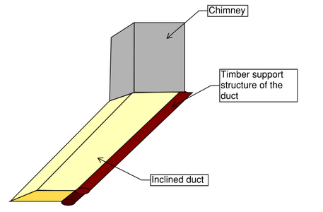
For the chimney ducts it is normally NSCE, then follow the procedure to assess the NSCE element.
Chimney ducts strength is assumed to be sufficient because they are small length closed structures with high stiffness
(high support for the perpendicular walls in the out-of-plane demand).
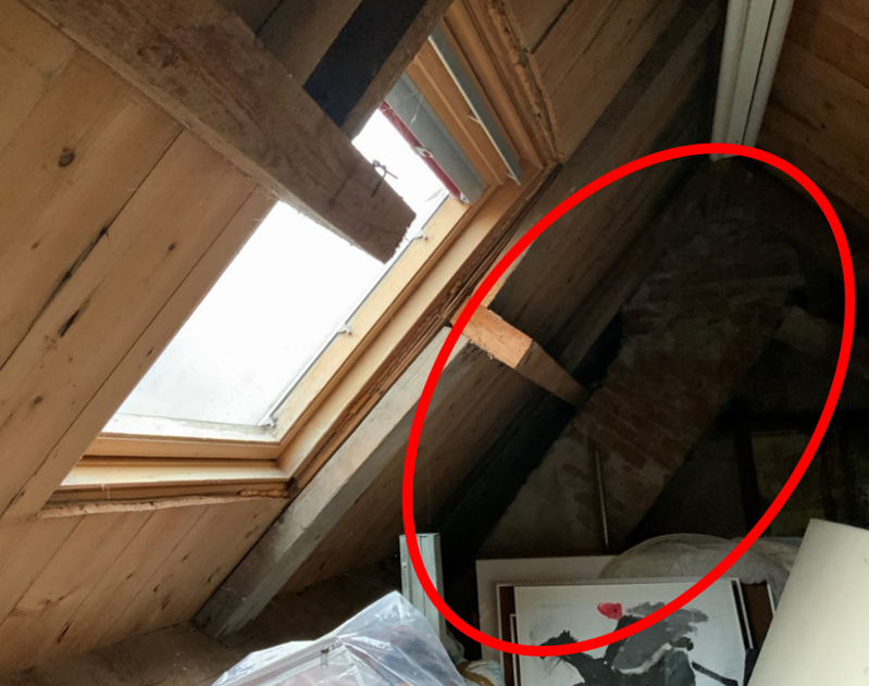
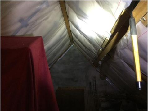
In case of inclined ducts the situation is different. They either shall be supported by a timber frame or be replaced
by lighter weight ones. If the latter is chosen, the chimney on top shall be replaced by a light weight one as well
because, if we remove the duct below the chimney requires support. GMC provides measures for supporting and replacing
the inclined ducts. However, it is highly recommended to support the inclined ducts with timber frames instead of
replacing them as it is, by far, a cheaper solution. In this case the chimney shall not be replaced anymore.
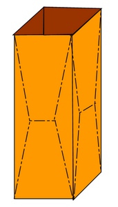
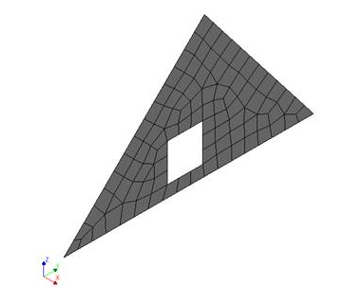
3.1 - When using semi-probabilistic assessment to assess a triangle wall, how to decide the
height and center of gravity? Refer to the below pictures.
The height should be till the highest point.
The center of gravity is the mass center of the element.
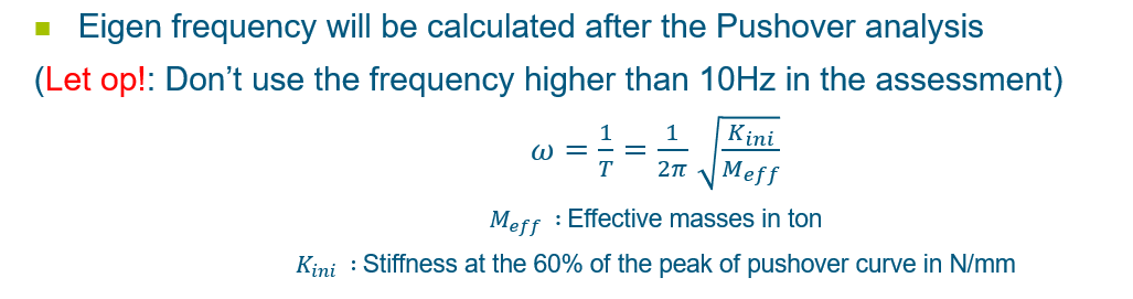
4.1 - The frequencies for NSCE assessment for NLPO and NLTH. Obtained from eigen frequency
analysis of the flexbase of entire model? Or somewhere else? Additionally should these be
based on the eigenfrequency of the entire model, or of the individual elements (in case of
outer leaves for example)?
Here the frequency refers to the fundamental frequency of the building.
For NLPO: the frequency T 1 for the assessment can be derived from the bilinearized push-over curve at the
performance point. Use 3 Hz as a reference in this case.
Figure 161 Formula to calculate the frequency from the results of NLPO analyses
For NLTH: if there is no clear dominate eigenmode, use 3 Hz for the assessment.
5.1 - We now obtain the overburden load based on the A1 Static analysis for each individual
wall. However, this is based on the assumption that during the earthquake period, there
will never be complete loss of compression at the top of the wall, even due to possible
overturning. Is this a correct assumption? Sometime we do see loss of connection between
the wall and the floor.
The overburden load obtained from static analysis is sufficient.
5.2 - When we have a end wall connected at the floor level, how do we consider the overburden
load from the upper gable wall?
Take the following object as the example, the whole mass of the gable wall is resting on the lower part, so you can
distribute that whole mass pragmatically but realistically as imposed load on the lower part. For example the pier on
the left will carry about 1/3 of the whole gable and the pier on the right 2/3.
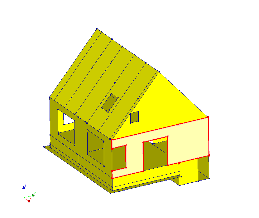
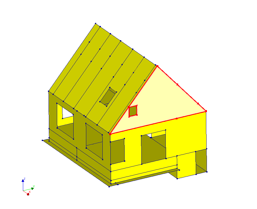
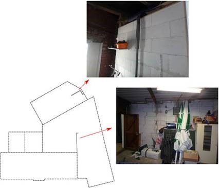
6.1 - For the gable wall in the following picture, is it correct to separate the assessment of
the gable wall into these two parts? Do we need to assess the part where the outer leaves
fall onto the roof? Do we need to assess the part where the outer leaves fall into the
area of the exit route?
As is shown in the following picture, only the top triangle part is defined as gable wall. In this case we assume that
there is a proper connection of the outer leave to the roof elements. Therefore, the generic assessment for the gable
wall can be applied.
Figure 163 The definition for gable wall (in red contour).
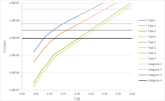
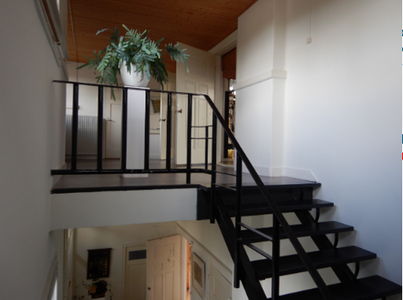
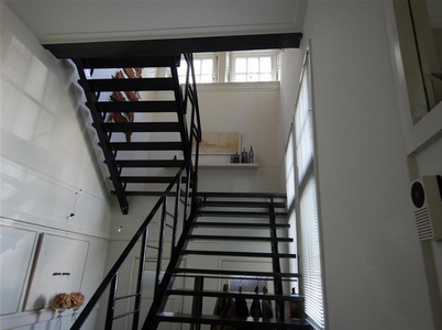
7.1 - How to assess the stairs? Generic risk assessment by assuming the category of chimneys is
applicable? Timber staircases would generally pass on the first category, Mortal danger.
However, for heavier staircases this process is still a bit unclear.
In case of timber stairs, no need to assess. See NPR 4.3.6.1 condition 1.
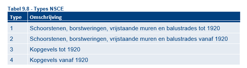
In case of masonry or concrete, use the generic risk assessment. This is comparable to gable wall from 1920 (type 4 in
table 9.8 from UPR), category 1. From the below graph we can use 0.35 g as the capacity.
Figure 164 Reproduction and extrapolation (dotted) from figure J.1 NPR9998:2018
For the stair cases, if they are timber or steel, their failure mode would be predominately vertical. In reality we
don’t see them failing with gravity. The vertical component of the earthquake loads are very low compared to the
horizontal ones. Those stairs are flexible in the horizontal direction, in which case they are considered to be safe.
Warning
This only applies for stairs in good condition. If you see rot timber, cracks, beams bending, etc. Then it
is a special case, discuss this with your lead engineer.
Figure 165 Reproduction and extrapolation (dotted) from figure J.1 NPR9998:2018.
In the left picture, the structure is an separate building:
First discuss with the lead engineer to see if it is in the scope of your object. Model the building in the model if
it is in the scope. If it is an separate building, the consequence class is CC1b, timber structure frame functions
as PSSE.
In the right picture, it is in the main building:
If it is in the main building, as an opening, no further action needed.
If the material is masonry, consider it as NSCE, comparable to a chimney in the generic risk assessment. The NSCE
category is category 2 in the below table from UPR.
The triangular parts of the dormer, on the sides are very stiff, which does not cause a problem. In this case, the
load is considered to be taken by the roof, so the dormer is deemed to be safe. On the other hand, the roof has a
opening in the place of dormer, which degrades the diaphragm behaviour. The loads from the dormer act on the edges of
the dormer, aka. the opening edges.
By experience dormers of size up until 3 m x 3 m are deemed to satisfy.
10.1 - How do we characterize a wall that at the end meets the roof plate, with the roof plate
spanning in the other direction, i.e. not supported by this wall. A cantilever or do we
assume some connection between wall and roof, i.e. et = -teff/2 and q=2.
It is not cantilevered, the wall is supported at the top.
The top support used for the assessment is depending on the support conditions.
For the angle we can use 0.025, overburden load on the wall is 0.
Walls of this material are masonry (glued) and it seems weaker than calcium silicate blocks in table F.2 of
NPR9998:2018+C1+A1:2020. Therefore, please apply NLKA for those aerated concrete walls as permitted per section
4.3.6.3 of NPR9998:2018+C1+A1:2020.
If the walls of gasbeton (aerated concrete) have a thickness of less than 75 mm, there is no need to check them.
In the UPR says aerated concrete density is: 800 kg/m3
So it should be used the NLKA tool and considered the density of aerated concrete in the UPR
In NPR9998:2018+C1+A1:2020 section 4.3.6.1. it is stated that no assessment is required for vertical NSCE elements that
are smaller than 3m and lighter than 60kg/m 2 because it does not pose potential lethal hazard.
The self-weight of the timber frame wall is about 20kg/m 2 based on the typical dimensions that are given below.
Therefore, no assessment is required for timber frame walls that are smaller than 3m. If this requirement is not met,
the timber frame wall should be assessed as indicated below.
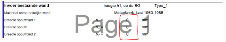
To check such a wall, L4 spreadsheet may be used. Go to ‘Wand vervangen_SK’ sheet. This sheet is used to check stability
of masonry walls retrofitted with timber frames. But this sheet may also be used to check timber frame walls as NSCE
once all parameters linked to masonry walls are set to zero, so that only the timber frame capacity is included in
calculation. See picture below.
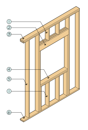
Figure 169 How to fill L4 sheet for timber walls.
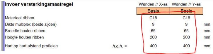
After all masonry wall parameters are set to zero, enter the parameters for timber wall. In the picture below,
parameters are set for a timber frame with C18 grade timber, 9mm thick multiplex board on both sides, columns (b x h1,
where ‘b’ refers to width of the timber column and ‘h1’ refers to depth of the timber column) of (65 mm x 200 mm)
with center to center distance of 400 mm.
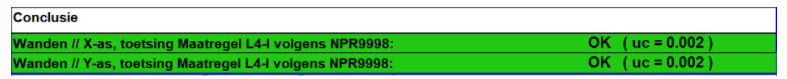
The unity check can then be read at the bottom of the page. For typical dimensions of timber frame, unity check
will be close to zero. Add decimals in the unity check value before adding it in the report.
12.2 - replace:: Timber walls – Knowledge team study
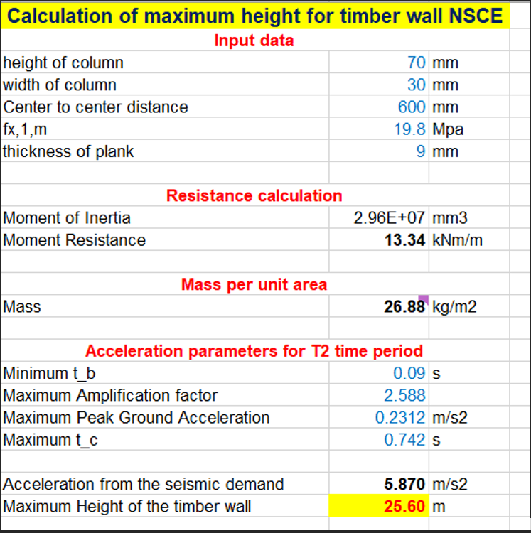
There was a sensibility study performed by the knowledge team showing that the timber walls don’t fail for heights of
more than 20m. So there is no need to access them. For a time period T2:
The moment resistance (Mrd) for a particular section is calculated.
The mass of the timber wall (m) is calculated and an additional mass of 20kg/m2 of gypsum plates are assumed that
covers the timber wall.
Regarding the calculation for the acceleration, further points are considered.
Minimum Tb value from the Groningen province.
Maximum Peak Ground Acceleration from the Groningen province (rho).
Maximum Amplification factor from the Groningen province (PGA).
Maximum Tc value from the Groningen province.
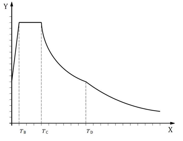
This gives a wide range of constant seismic demand, as shown in the image below. Important to note that the maximum
and minimum values for the acceleration parameters are not for a particular location but from the entire Groningen
province.
Using the above method, the seismic demand (Acceleration) is calculated. Finally, the following formula is used to
calculate the Maximum Height of the timber wall (h).
𝑀_𝑅𝑑=(4∗𝑚∗ℎ^2∗𝐴𝑐𝑐𝑒𝑙𝑒𝑟𝑎𝑡𝑖𝑜𝑛)/𝜋^3
In such a way, the maximum height for the timber wall can be calculated.
These points can be added to the starting point documents (UPR) for the NLTH and MRS, so that a generalized conclusion
is obtained.
The sheet for checking such walls is under development. This section will be updated once the sheet is developed,
checked and approved by knowledge team.
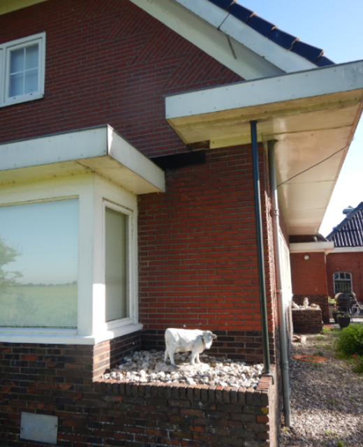
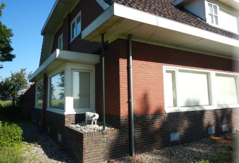
The cantilever shows that it has enough support connection to handle loads from wind and snow, which should be covered
already in the static situation.
These elements are not considered as NSCEs. Discuss with your lead engineer to see if these elements should be in the
model.