How to add strengthening measures in the model
This how to guide will explain Step 14: Closure of the protocol. Once the measures meeting has been done and the possible strengthening measures have been discussed, it is time to include the measures in the model of the object and rerun the analyses with the different earthquake signals. This section gives a guide on possible ways to include the strengthening measures in the model.
Adding Strengthening Measures
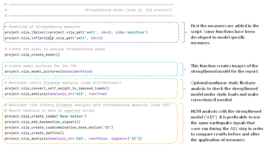
The strengthening measures are modelled in the mainscript, in the section labelled as ‘Strengthening phase’.
Below, a guide of the most commonly used measures is presented, with TGN >= 4. This guide comprises of a small summary of measure, its applicability and modelling recommendations. It is important to highlight that the retrofitting measures that can be applied on an object are specified in the GMC Catalogue.
The recommendations on how to model the retrofit are based on the BoD 7.0 (Please check the relevant section of the current BoD to get latest information); for the measures that are not described in the BoD, the engineer should consult with the lead engineer the most appropriate way to model them. Additionally, the measures that are available in the viiapackage are included in the list; Report Bugs, in case a measure has issues of feature request, in case more functionality if required from a measure.
L1 measures: Eliminate/Mitigate acute hazard
Measures in this category involve the strengthening or removal of some non-structural elements (NSCEs), specifically chimneys, glass windows and radiators. Strengthening measures for other NSCEs are not included in this group and can be consulted in the “L2”, “L4” or “L5” sections, depending on the failing mode of the element.
Because NSCEs are not included in the FEM model, these measures do not need to be incorporated in the script or in DIANA and their effect should be assessed independently, using the corresponding assessment tool depending on the case, Refer to ‘How to perform NSCE/NLKA analysis’.
If the measure involves removal or replacement of an NSCE (e.g.: L1-A: replacement of heavy chimney for lighter version or L1-C: removal of chimney duct) then the loads on the object must be updated to reflect the change (reduction) in weight.
L2 measures: Coupling
Coupling measures have the objective of connecting elements that are disconnected or strengthening existing connections that have resulted in failure during the NLTH analyses. Since coupling can alter load paths, it is important to carefully consider the impact of coupling strengthening measure on existing load paths. For example, creating connections between floors and walls will modify the load transfer and will result in higher gravitational and lateral loading of the walls that are now connected to the floors (might also result in higher loading of the foundations under those walls). On the other hand, the elements that were initially connected to the floors might experience a reduction of loading as a consequence of the new connections and the increase of redundancy.
Coupling measure can be modelled by adding an interface, hinge or fixed connection between the elements that need to be coupled. In case of modelling the coupling with an interface, this one should have linear properties (set the parameter ‘is_linear’ to ‘True’). The BoD recommends which type of connection to use when applying some measures; for those measures that are not specified in the BoD, the engineer should discuss how to model them with the lead engineer.
Next, some examples of how to create a node hinge, a line hinge and an interface to couple elements.
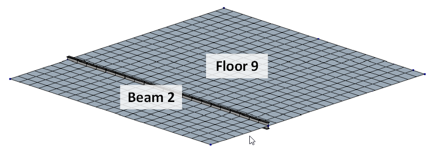
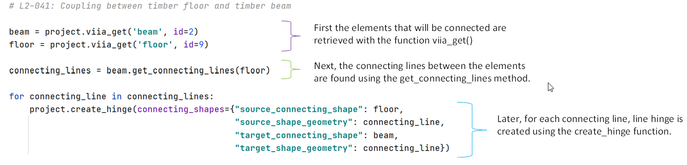
Example: how to add a line hinge to connect a timber floor to a steel beam (measure L2-041)
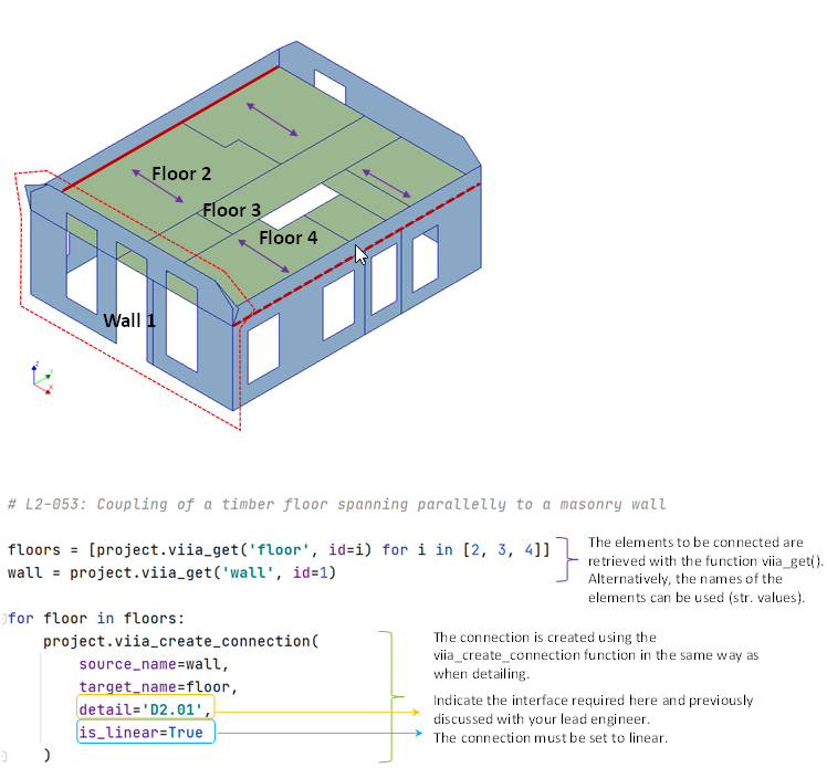
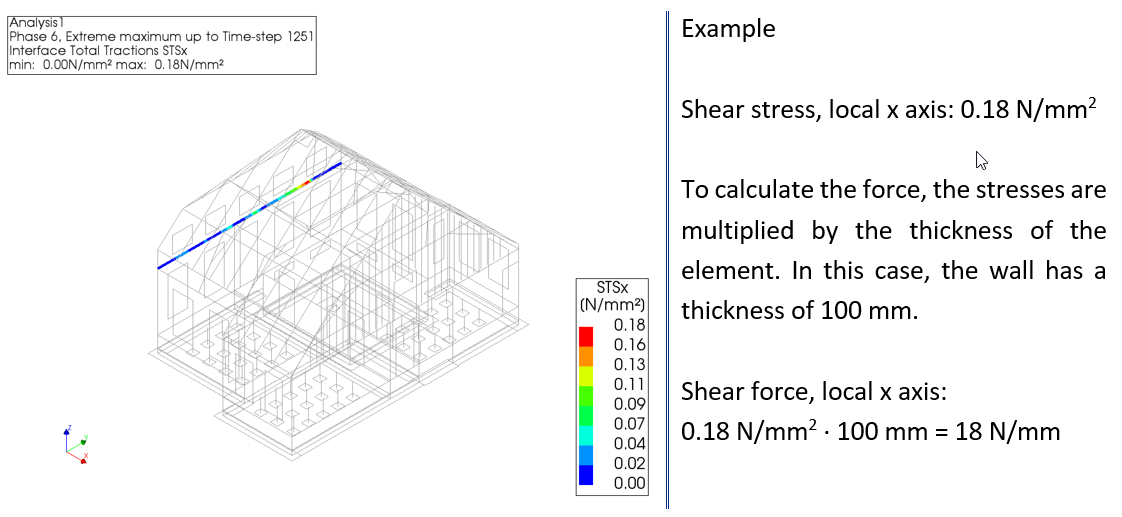
Example: how to add a linear interface to connect a timber floor spanning parallel to a masonry wall (measure L2-053, Note: this measure is not specified in the BoD, so consult with your lead engineer the most appropriate way to model it)
When a linear interface is applied to the model, tensile, compression and shear stresses must be checked and the calculations should be included in Appendix C4 for the governing signal; contour plots of the stresses for the non-governing results should be presented in Appendix C7. To obtain the normal stresses in DIANA indicate STNy; to obtain the shear stresses indicate the STSx and STSz. Since the stresses have units of force/area, they should be multiplied by the thickness of the wall to obtain the force by unit length.
Next, a list of the coupling connections that have a TGN ≥ 4 are presented with their corresponding modelling recommendation.
Measure L2-001
Applicability: sloping timber roof to timber or concrete floors
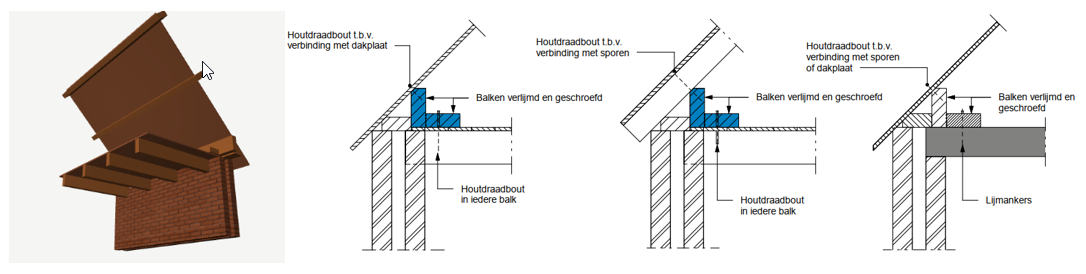
The goal of the measure is to create a connection between a sloping timber roof and a floor. The coupling is achieved through the installation of timber beams between both elements. Important to note that the measure can be installed from the interior of the house as long as the anchors can be installed to the beams of the roof. If this is not possible, the connection must be made directly to the roof plate and the anchors must be installed from the outside.
Modelling: the engineer should consult with the lead engineer the most appropriate way to model this measure. Variant 1 of the measure concerns the coupling of the roof to timber floors, while variant 2 considers the coupling for concrete floors. Both variants have a shear strength of 4.7 kN/m.
Measure L2-005
Applicability: concrete floor or roof to masonry wall
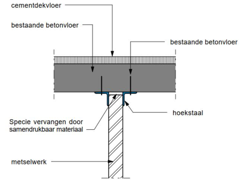
Concerns the connection of a strengthened concrete floor to an unstrengthened masonry wall using steel angles. Can also be used for sloping elements (including roofs). The goal of the measure is to allow cohesion between both elements.
Modelling: The measure can be modelled with a node hinge or line hinge. The measure has only one variant with has a tensile capacity of 3.2 kN/m.
Measure L2-013
Applicability: floor to floor or flat roof to flat roof (timber or concrete)
The measure has the goal of connecting two floors or flat roofs through a steel plate placed on top of the floor. The plate can be Z shaped to allow connecting floors where there is a small jump in between the two elements.
Modelling: the engineer should consult with the lead engineer the most appropriate way to model this measure. The measure has two variants that consider the possibility of connecting timber elements (shear capacity = 5.8 kN/m) or concrete elements (shear capacity: 18.3 kN/m).
Measure L2-015
Applicability: timber trusses where the elements are not coincident at the nodes
The goal of this retrofitting measure is to provide a connection in nodes of the truss where no connection exists, or strengthen an existing connection. The coupling is achieved through a bolted connection.
Modelling: the engineer should consult with the lead engineer the most appropriate way to model this measure.
Measure L2-025
Applicability: perpendicular solid masonry walls (interior or exterior) that are not coupled between them
The measure has the purpose of creating a connection between perpendicular masonry walls that are not connected. The connection is made by installing steel angles in the inner corner between the two walls and anchors. The measure can be used in corner connections or in T connections of walls.
Modelling: the engineer should consult with the lead engineer the most appropriate way to model this measure. Note that it is preferable to use measure L2-043 for this type of connection, where steel rods are placed between the joints of the bricks or anchored to create the connection.
Measure L2-041
Applicability: timber floors to steel beam
Retrofitting measure that strengthens the connection of timber floor beams that are simply supported on a steel beam. The timber beams are secured to the steel beam with steel strips to prevent the beams from sliding out.
Modelling: This measure can be modelled with a node hinge or line hinge.
Measure L2-044
Applicability: non-load bearing inner walls
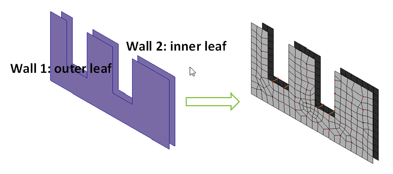
The goal of the measure consists of disconnecting non-load bearing walls from primary and secondary structural elements and providing an adequate support at the top of the wall to prevent out of plane movement at the top.
By disconnecting non load-bearing walls from floors, no shear force is transmitted to the wall when seismic actions occur parallel to the direction of the wall, this prevents the wall from failing. The following figure illustrates the de-coupling measure.
Modelling: the engineer should consult with the lead engineer the most appropriate way to model this measure.
Measure L2-053
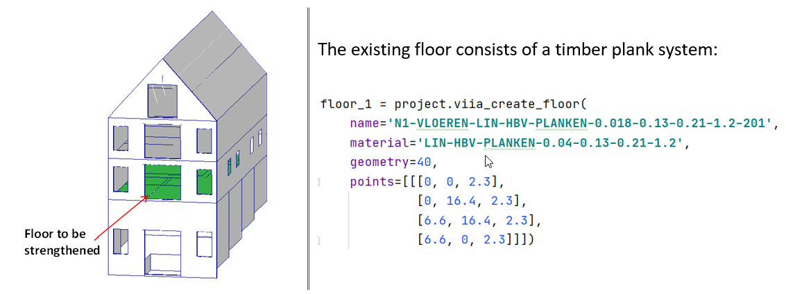
Applicability: timber floors spanning parallel to masonry walls (solid or cavity)
This measure couples the timber floor system to a masonry wall spanning parallel to the direction of the floor. The goals of the measure include enabling the transfer of lateral forces from the floor to the wall and preventing out-of-plane failure of the wall. The coupling is performed by installing anchors between the timber beam and the wall; several variants are available which take into consideration if the wall is a cavity wall or solid wall, and offer different capacity values.
Modelling: the engineer should consult with the lead engineer the most appropriate way to model this measure.
Measure L2-054
Applicability: timber floors spanning perpendicular to masonry walls (solid or cavity)
This measure is similar to L2-053 but it considers the case where the timber floor is spanning perpendicularly to the wall. The goals of the measure include enabling the transfer of forces from the floor to the wall and preventing out-of-plane failure of the wall. The coupling is made by anchoring the timber beams to the wall and similarly to measure L2-053, several variants are available according to the specific situation.
Modelling: the engineer should consult with the lead engineer the most appropriate way to model this measure.
Measure L2-055
Applicability: timber roof purlins spanning perpendicular to masonry facade walls (solid or cavity)
The goal of the measure is to prevent the collapse of the top masonry facade of the building (gable walls). The wall is coupled to the timber purlins of the roof with anchors. The connection therefore allows the forces from the gable wall to be transferred to the timber roof.
Modelling: the engineer should consult with the lead engineer the most appropriate way to model this measure.
L3 Measures: Diaphragm action
This category of measures involves the strengthening of floors and roofs to increase the diaphragm action and the transfer of shear forces (shear capacity). Several measures tackle this issue and include adding a new diaphragm or strengthening an existing diaphragm.
Measure L3-A
Applicability: timber floors or timber flat roofs
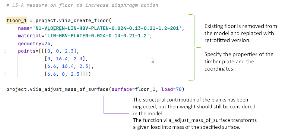
The retrofitting consists of adding two layers of multiplex panels to the top of existing timber floors or flat timber roofs. If the existing floor/roof system consists of timber planks, the strength and stiffness of the planks is ignored. The purpose of the measure is to increase the diaphragm action of timber floors of timber flat roofs to improve the transfer of loads.
Modelling: The measure can be modelled by using the function viia_l3a().
The measure can be modelled by adjusting the material and geometric properties of the modelled floor/roof to
update the in-plane shear stiffness and density. The existing floor/roof can be removed and substituted with an
equivalent timber plate system, thickness of the plate = 24 mm (2 plates of 12 mm). If the existing floor/roof consists
of a plank system, the weight of the planks should be added to the mass of the modelled retrofitted roof.
Example - How to model L3-A measure to strengthen a timber floor
Measure L3-B
Applicability: timber floors or timber flat roofs
Compared to the L3-A, this measure is applied at the bottom of the floor. Because this does not influence the way the
measure is applied in the model, refer to measure L3-A for the modelling approach. For this measure the function
viia_l3b() is available.
Measure L3-D
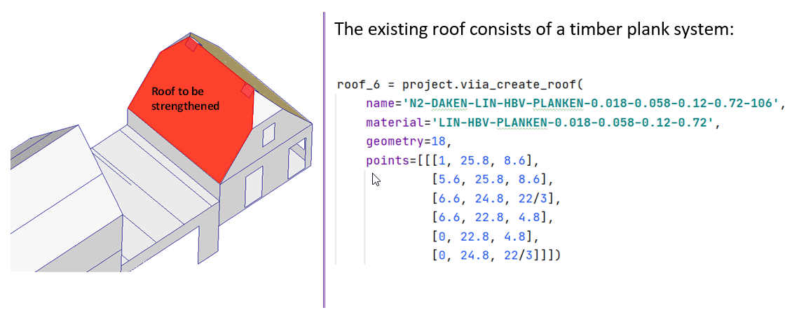
Applicability: sloping timber roofs
The retrofitting consists of the application of one multiplex panel of 12 mm thick to the bottom of an existing sloping timber floor. The goal of the measure is to improve the diaphragm action while maintaining the existing system and external appearance of the roof.
Similar to measure L3-A, in cases where the existing system consists of planks, the resistance and stiffness of those planks is ignored. The measure has a variant that considers the possibility of having insulation in the roof.
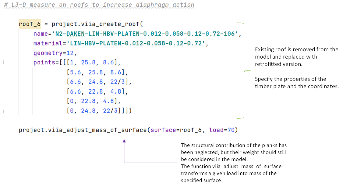
Modelling: The measure can be modelled by using the function viia_l3d(). The
retrofitting measure is modelled by adjusting the geometry and material properties of the modelled roof.
The existing roof can be removed and substituted with an equivalent timber plate system (thickness of the plate =
12 mm). If the existing roof consisted of a plank system, the weight of the planks should be added to the mass of the
modelled retrofitted roof.
Example: how to model L3-D measure to strengthen a sloped roof
Measure L3-E
Applicability: sloping timber roofs
This measure is an alternative to measure L3-D, with the difference that the additional multiplex plate is installed from the outside of the roof. This measure is therefore selected when the additional diaphragm cannot be installed from the bottom of the roof.
Modelling: The measure can be modelled by using the function viia_l3e(). To
model this measure, modify the material and density parameters of the roof according to table 8.3 (DIANA) or 8.4
(ABAQUS) of section 8.2.2 of the BoD.
Note
In the DIANA model, this measure could be modelled in the same way as L3-D, it would make no difference in the analysis if the measure were applied from the inside or outside, unless it is decided that eccentricities must be considered.
Measure L3-G
Applicability: steel or timber laminated roofs (platen)
This retrofitting option concerns the application of steel or timber braces (depending on the material of the roof and beams) to the existing roof to improve the diaphragm action (stiffness and shear capacity). The braces consist of steel or timber elements (depending on the variant) that are installed on the bottom (inside) face of the roof, spanning diagonally between the rafters or beams of the roof.
Modelling: The measure can be modelled by using the function viia_l3g(). The
measure is modelled by adding the actual bracing elements to the model, which means that this is an object-specific
measure where the most appropriate braces will be selected and dimensioned for each object.
Measure L3-L
Applicability: concrete floors
The goal of the measure is to strengthen concrete floors for diaphragm action. This is achieved by applying FRP strips with epoxy adhesive to the surface, specifically on the sides that undergo tension.
Modelling: the engineer should consult with the lead engineer the most appropriate way to model this measure. The measure has two variants which consider the possibility of applying the retrofitting on the top or bottom surface f the floor. Both options have a shear strength of 9.3 kN/m.
Measure L3-M
Applicability: timber floors or timber flat roofs
The purpose of this measure is to improve the diaphragm action in timber floors or flat timber roofs, maintaining the existing elements. This is achieved by adding OSB plates on top of the floors. It is important to highlight that this measure should only be used in areas where there are sufficient floor or roof beams that can take the lateral forces and allow diaphragm behaviour.
Modelling: The measure can be modelled by using the function viia_l3m(). The
engineer should consult with the lead engineer the most appropriate way to model this measure. The retrofitting measure
has 5 variants that consider if the element is a floor or roof and if it includes or excludes isolation layers. All
variants have a shear force resistance of 8.5 kN/m.
Measure L3-N
Applicability: locations (floors of flat roofs) where diaphragm action is needed
The objective of the measure is to add a new floor where no floor is present and provide diaphragm action. For example, in attics, floor openings or levels where the original floor system was removed. A new beam system of 46 mm x 156 mm, c.t.c. = 600 mm is added, and two layers of 12 mm thick plywood plates (glued together) are installed and connected to the beams with screws. The connection of the floor system with the walls is obtained by applying L2 measures in the desired locations.
Modelling: the engineer should consult with the lead engineer the most appropriate way to model this measure. The measure has a total of 5 variants, which include different possible locations (ground floor, storey floor or flat roof) and the possibility of having insulation. The in-plane shear strength is the same in all cases (55 kN/m).
L4 Measures: Walls Out Of Plane
This set of measures are used when strengthening walls against out-of-plane failure. Measures include installing additional wall elements, filling the voids of cavity walls, or strengthening existing walls.
Measure L4-B
Applicability: any masonry walls with windows covering between 20% - 70% of the area
The goal of the measure is to prevent out-of-plane failure of the wall and adding coherence in case of in-plane mechanisms. The measure consists of the installation of a series of vertical (HE 100) and horizontal steel (IPE 100) profiles on one side of the wall. This measure is intended for walls with large windows, covering between 20% and 70% of the surface of the wall. In case of cavity walls, the profiles are applied to the inner leaf and cavity wall ties must be added to restrain the outer leaf. Note that this measure is only used in cases where the out of plane forces are very high; otherwise, it is preferable to use L4-G.
Modelling: The measure can be modelled by using the function viia_l4b().
Check your DIANA model to ensure that strengthening is correctly applied, and that material property of the
strengthening element is matching with the latest BoD. Correct manually and report as bug if there is a mismatch.
Note
Note that this measure has a TGN = 2. It is recommended to find an equivalent measure with TGN >= 4.
Measure L4-D
Applicability: masonry cavity walls
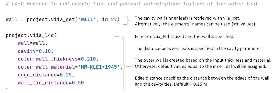
The measure’s goal is to prevent the out-of-plane failure of the outer leaf of cavity walls by installing cavity ties to connect it to the inner leaf. Existing cavity ties can be ignored or included in the calculation depending on each case.
Modelling: The measure can be modelled by using the function viia_l4d().
For modelling this measure, the cavity wall ties can be modelled as usual, with the same properties as the existing wall
ties (section 6.4.1 of the BoD). The walls where the measure is to be applied should be specified, as well as the
distances from the ties to the edges of the wall. The function works if both leafs have been modelled or if only one
leaf has been modelled. In the latter case, some additional parameters are required, and the function will add the
second leaf before adding the corresponding ties.
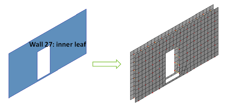
Example: how to strengthen cavity walls when the outer leaf has been modelled.
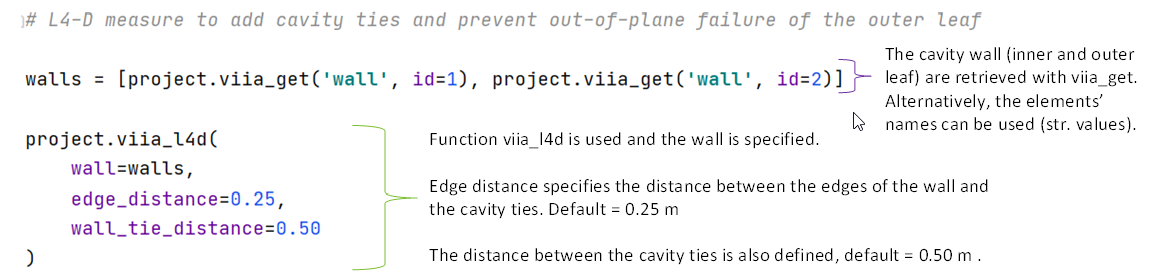
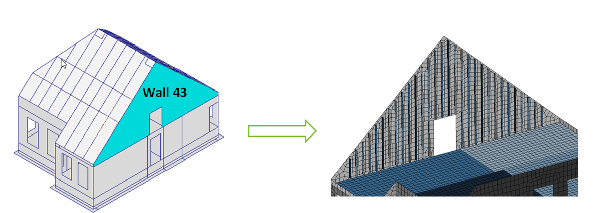
Example: How to strengthen cavity walls when the outer leaf has not been modelled.
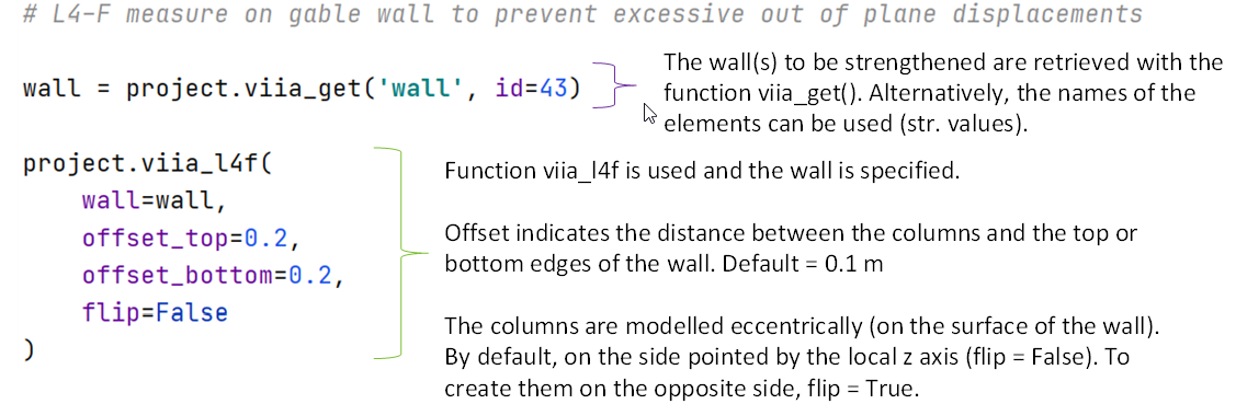
Measure L4-F
Applicability: any masonry wall (solid walls and cavity walls)
A second wall consisting of an HSB wall is installed against an existing wall. The timber columns can be spaced every 400 mm or 600 mm. This additional wall Improves out of plane bending resistance. In case of dealing with cavity walls, wall ties must be added to ensure the connection between the outer and inner leafs.
Modelling: The measure can be modelled by using the function viia_l4f(). The
wall where the measure will be applied needs to be specified. Additional parameters such as the bottom and upper offset
of the beams with respect to the wall edge can be specified, as well as the direction of the eccentricity. Keep in mind
that this function will apply the timber columns with a c.t.c spacing of 400 mm. Even though the contribution of the top
timber plate is ignored, the density of the multiplex and finishing (17.2 kg/m2) is added to the density of the wall or
inner leaf.
If strengthening a cavity wall, remedial wall ties must be added between the leafs with a horizontal spacing of 600 mm and vertical spacing of 900 mm. The ties have the following properties:
Materials |
|---|
|
For more information on the details regarding the properties that the function considers when modelling this measure, refer to section 8.3.3 in the BoD.
Example: how to model L4-F measure to strengthen a masonry wall
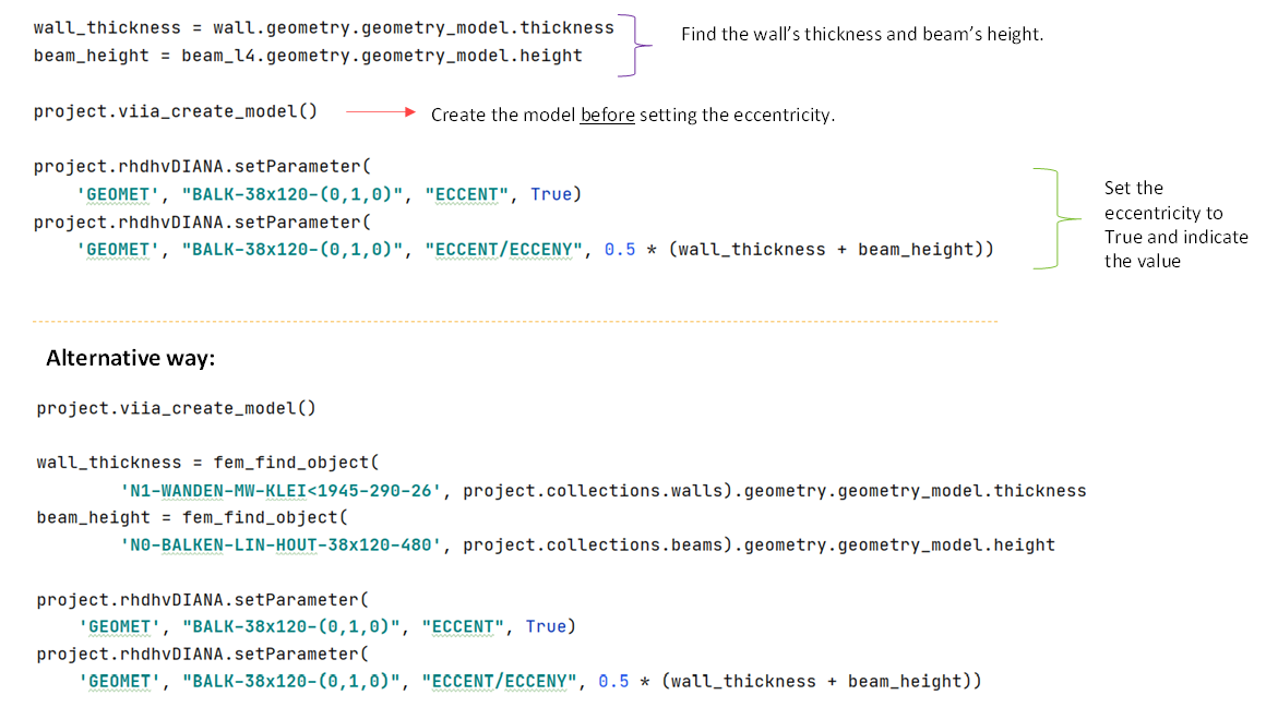
Measure L4-G
Applicability: any masonry wall (solid walls and cavity walls)
This measure is similar to L4-F with the difference that it is applied on walls where the openings occupy between 20% and 70% of the surface. Similarly to L4-F, an HSB wall is installed on the wall. Columns and horizontal elements of 38x120 mm frame the openings. The timber columns can be spaced every 400 mm or 600 mm. This additional wall improves the out of plane bending resistance. In case of dealing with cavity walls, wall ties must be added to ensure the connection between the outer and inner leafs.
Modelling: The measure can be modelled by using the function viia_l4g().
In order to consider the eccentricity of the 38x120 mm elements, the following script can be adapted in each case:
Measure L4-I
Applicability: load bearing masonry walls (solid or cavity walls) supporting timber floor/roof
The purpose of this measure is to eliminate risk walls and reduce mass. The measure consists of the replacement of an existing load bearing masonry wall with a load bearing HSB wall.
Modelling: The measure can be modelled by using the function viia_l4i().
Check your DIANA model to ensure that strengthening is correctly applied, and that material property of the
strengthening element is matching with the latest BoD. Correct manually and report as bug if there is a mismatch. The
measure has two variants, one with a spacing of 400 mm between the timber columns and another with a 600 mm spacing.
Both measures have an out-of-plane bending strength of 27.5 kNm/m.
Measure L4-K
Applicability: masonry walls (solid and cavity walls)
The goal of this measure if to prevent out-of-plane failure of relatively thick and heavy masonry walls and to provide coherence in case of collapse mechanisms. This can be considered as a heavier version of L4-F. An HSB wall is installed against an existing wall. The timber columns can be spaced every 400 mm or 600 mm. This additional wall provides the existing element with more stiffness and bending resistance. In case of dealing with cavity walls, wall ties must be added to ensure the connection between the outer and inner leafs. The measure is applied on the inside face of walls.
Modelling: the engineer should consult with the lead engineer the most appropriate way to model this measure. The measure has 4 variants that consider the possibility of having insulation, different spacing of the timber columns and solid or cavity walls. The flexural resistance is 4 kNm/m for the variations that involve a 600 mm column spacing, or 5.7 kNm/m for variations with 400 mm column spacing.
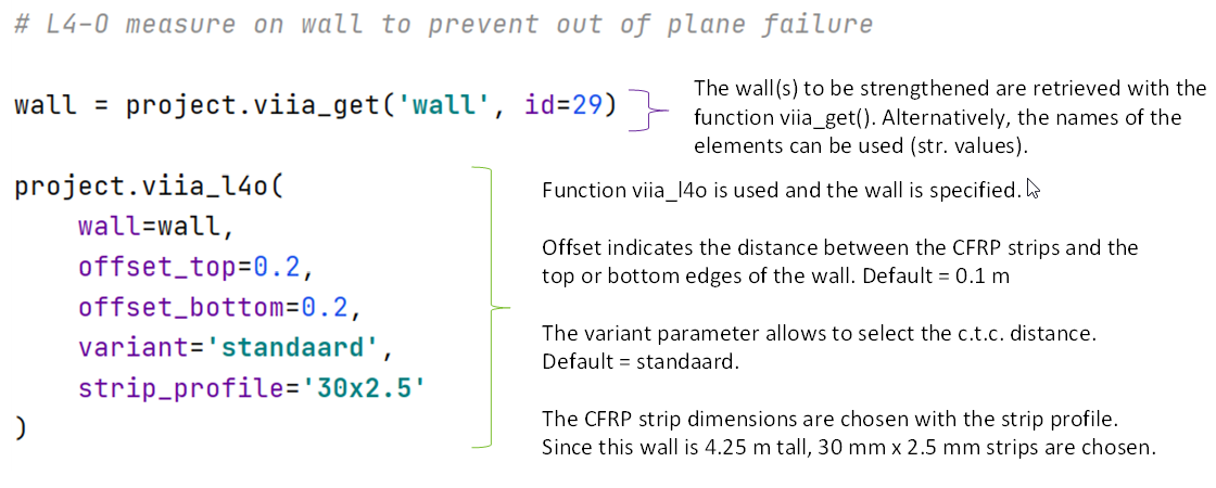
Measure L4-O
Applicability: any masonry wall (solid walls and cavity walls)
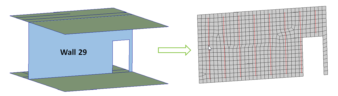
This measure consists of the application of quakeshield strips on masonry walls to prevent the out-of-plane failure of the wall and increase the coherence in case of in-plane collapse mechanisms. The quakeshield in this case consists of carbon fibre reinforced polymer (CFRP) strips that are attached with epoxy adhesive on milled slots on the surface of the wall. The measure can be applied on any wall, interior or exterior, as long as the measure is always applied on the face of the wall facing the inside of the house, and as long as the openings cover less than 20% of the surface. In case of cavity walls, remedial wall ties are needed to support the opposite leaf.
Modelling: The measure can be modelled by using the function viia_l4o(). The
function adds vertical CFRP strips to the wall; however; the remedial wall ties in case of strengthening cavity walls
should be added manually in the same way as for measure L4-F. When using the function, the wall where the retrofitting
will be applied needs to be specified. The center to center. distance can be specified through the ‘variant’ parameter:
‘standard’ (default): 1.0m
‘verzwaard’: 0.75 m
‘top-zwaar’: 0.5 m
‘lichter’: 1.25 m
The geometry of the CFRP strips is determined by the height of the wall, as the governing failure mode should be slip. As a result, the higher the wall, the larger the CFRP should be, see Table 2. The geometry of the CFRP strips can be specified through the ‘strip_profile’ parameter. Optional parameters include the bottom and top offset distances to the edge of the wall.
Table: CFRP parameters from Table 8.9 of the BoD 7.0 |
|||
|---|---|---|---|
Strip |
Maximum wall height (m) |
Cross sectional area (m2) (CROSSE) |
Perimeter (m) (PERIME) |
CFRP-strip 20 mm x 1.4 mm |
2.56 |
2.8000E-5 |
4.28000E-2 |
CFRP-strip 30 mm x 1.4 mm |
2.62 |
4.2000E-5 |
6.28000E-2 |
CFRP-strip 30 mm x 2.5 mm |
4.52 |
7.5000E-5 |
6.50000E-2 |
Specific design |
Equation 8-3 |
w * h | 2 * w + 2 * h |
|
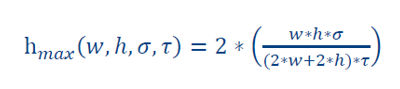
- where:
w: width of the strip
h: height of the strip
\({\sigma}\): 1800 N/mm2, maximum tensile stressof the strip
\({\tau}\): 1.43 N/mm2, maximum shear stress between the strip and the masonry
After the analysis, check that the tensile stresses in the CFRP strip do not exceed 2800 N/mm2 (maximum tensile stress)
Example: How to model L4-O measure to strengthen a masonry wall
Measure L4-R
Applicability: Large masonry walls (solid and cavity walls)
The goal of this measure is to prevent out-of-plane collapse and to provide coherence in damaged walls. The measure consists of a series of vertical steel profiles and horizontal timber elements placed between the vertical elements. This retrofitting measure is applied on the inner side of the wall.
Modelling: The measure can be modelled by using the function viia_l4r().
Check your DIANA model to ensure that strengthening is correctly applied, and that material property of the
strengthening element is matching with the latest BoD. Correct manually and report as bug if there is a mismatch.
Note
Note that this measure has a TGN = 1. It is recommended to find an equivalent measure with TGN >= 4.
L5 Measures: Walls In-Plane
The measures in this section target in-plane failure of walls. In-plane failure happens when the stability walls do not have sufficient capacity to withstand the earthquake forces that happen parallel to their plane. In-plane strengthening measures usually also prevent possible out-of-plane failures. In case that after retrofitting the element against in-plane failures it still requires out-of-plane measures, these can be considered and combined with the L5 measures into a single measure.
Common retrofitting measures against in-plane failure include jacketing, installing new walls, reinforcing with quakeshield, amongst others.
Measure L5-A
Applicability: masonry walls that transfer large forces (not for small buildings)
The measure has the goal to avoid the collapse of the element; if applied on both sides it can also prevent out-of-plane failures. It consists of the installation of a steel net against the existing wall, which is later jacketed with mortar. An L2 measure is necessary to couple the top of the wall to the floor. It is important to highlight that this L5 measure increases considerably in-plane capacity of the wall; consequently, the strength of the foundations needs to be checked and increased if necessary.
Modelling: To model this measure, the function viia_l5a() can be used. The
wall where the measure needs to be applied should be specified, as well as the eccentricity of the measure (on which
side or sides of the wall ‘application_type’). The application type is defined in the direction of the normal vector of
the wall (the z-axis).
project.viia_l5a(wall='wall1', application_type='negative')
Measure L5-B
Applicability: masonry wall, preferably located in ground or first storeys
This measure consists of replacing an existing masonry wall and installing a new concrete wall in its place. This new wall has a thickness of 200 mm. When applying this measure, additional mass with respect to the original element should be considered; moreover, the foundations should be assessed and strengthened if necessary.
Modelling: To model this measure, the function viia_l5b(). Check your DIANA
model to ensure that strengthening is correctly applied, and that material property of the strengthening element is
matching with the latest BoD. Correct manually and report as bug if there is a mismatch.
Measure L5-D
Applicability: walls or roofs.
Steel or timber elements/frames can be added in new locations to increase the in-plane resistance of the structure. The measure can also be used to substitute existing elements. As mentioned, the frames can be composed of steel or timber elements and their geometries can be selected depending on the specific requirements.
Modelling: To model this measure, the strengthening elements should be added in the model, following the usual guidelines for timber (section 6.7.1 in the BoD) or steel (section 6.5 in the BoD). If the measure if being used to replace an element, then remove the existing element from the model.
Measure L5-N
Applicability: solid interior masonry walls.
This measure strengthens existing masonry walls by installing a new reinforced concrete wall against it. The new wall is 150 mm thick with two layers of steel reinforcement. This new wall is applied on one side of the wall and connected to the existing wall through anchors.
Modelling: This measure is similar to measure L5-A, the measure can be modelled by using the function
viia_l5n(). Check your DIANA model to ensure that strengthening is correctly
applied, and that material property of the strengthening element is matching with the latest BoD. Correct manually and
report as bug if there is a mismatch. Foundation elements should be checked due to the increase loading resulting from
this measure.
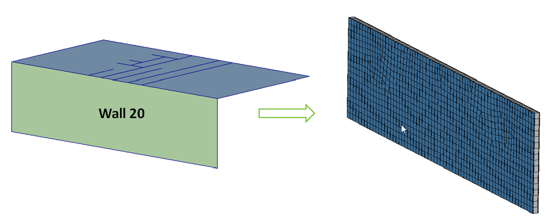
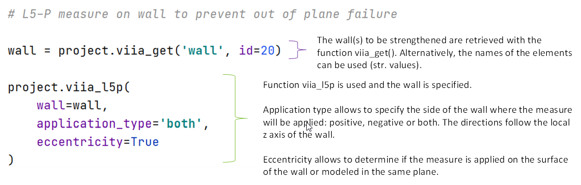
Measure L5-P
Applicability: masonry interior or exterior walls
The measure consists of applying 20 mm of sprayed concrete on both sides of an existing masonry wall (Quakeshield). The sprayed concrete is reinforced with a CFRP net. The measure can be applied on one or two sides of the masonry wall; if applied on both sides out-of-plane failures can also be prevented.
Modelling: To model this measure, the function viia_l5p() can be used. The
wall to be strengthened must be specified as well as the side(s) of application and the eccentricity. When applying this
measure, foundations should be assessed to determine if they have the required capacity due to the increased loading.
Example: how to model L5-P measure to strengthen a masonry wall
L6 Measures: Foundation
This set of measures involve the strengthening of foundations against insufficient capacity of the foundations or soil, settlements and other issues. The assessment of foundations and the recommendation of strengthening measures is performed by the geotechnical advisor.