How to read 3D scan
In VIIA inspections often 3d scans are made of the building. These scans can be very useful for the structural engineer to understand the structure and to retrieve dimensions that were not recorded during the inspection. It will also help to define the connections between the building components. This how-to guide will describe the software that you can use to work with the 3d pointcloud.
In this guide two different programs are described that can be used to open 3D scan files. These are Z+FlaserControl and Autodesk ReCap. Which software is suitable in each case depends on the type of the available 3D scan files.
In the following sections there is information about the types of 3D scan files, the structure of the folders generally available on BOX, where they are saved, as well as some instructions about the use of Z+FlaserControl and Autodesk ReCap.
Z+FlaserControl
The folder structure with files containing the viewpoints from the 3D scan are shown in Figure 11. The start.bat file contains the instructions to start the software automatically. Always save the whole folder locally to your computer. Then, the 3D scan can be opened with the Z+FlaserControl software by double-clicking the start.bat file.
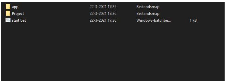
Figure 11 Content of folder that contains 3D scan files which can be opened with Z+FlaserControl
The window in Figure 11 pops-up. Select the first box only and allow access (Toegang toestaan). This would take you to the GUI start screen of Z+Flaser control, which is shown in Figure 12.
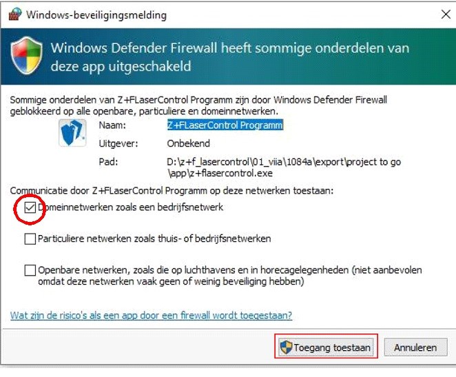
Figure 12 Allowing access to Z+Flaser control
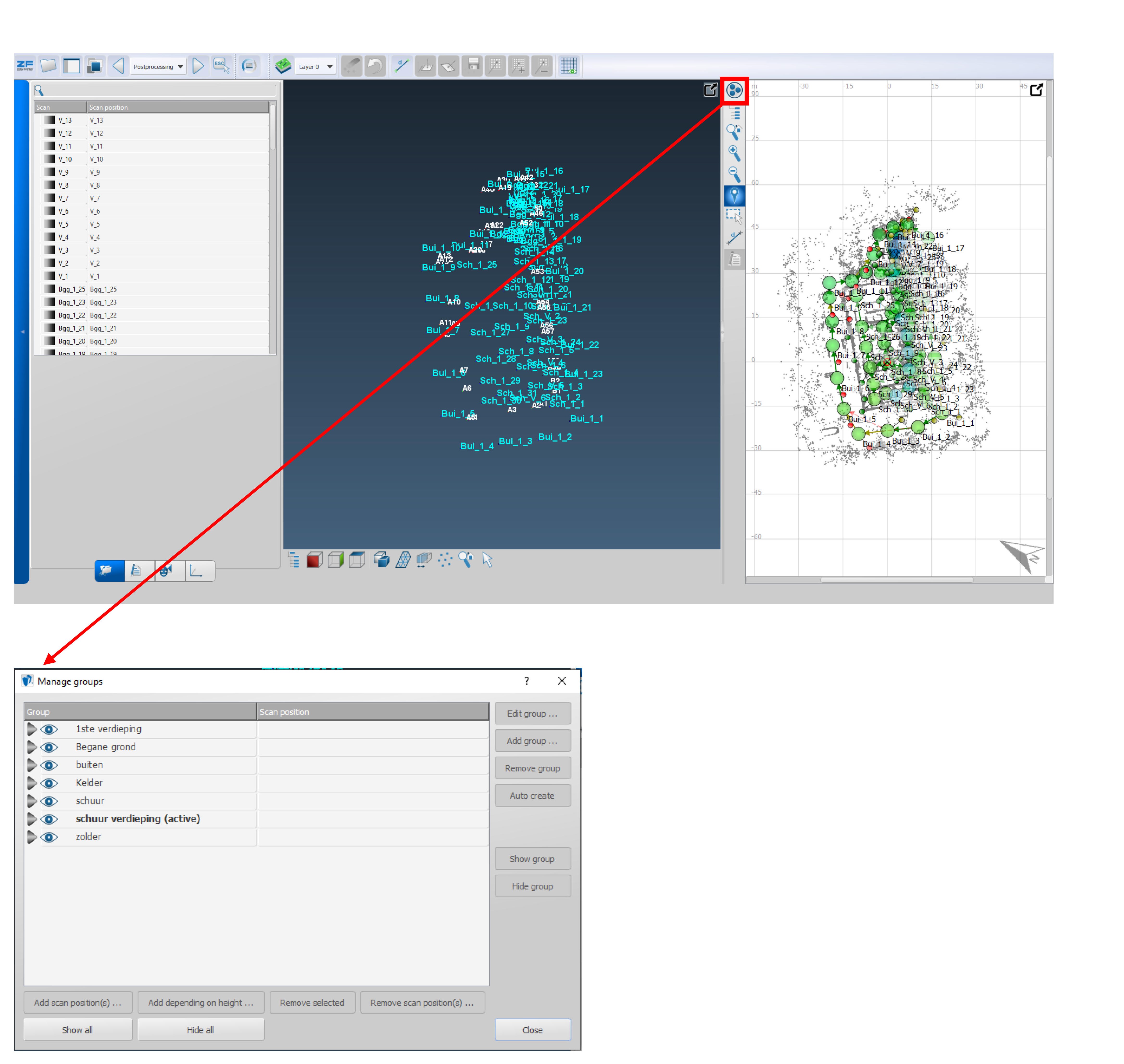
Figure 13 (a): Start screen of Z+Flaser control, (b) list with groups of viewpoints
Clicking the button Manage Groups opens the window which is shown in Figure 13. Here you should see the viewpoints arranged in groups. Clicking on the respective eye can show/hide the viewpoints of each group on the plan view (top right window in Figure 14).
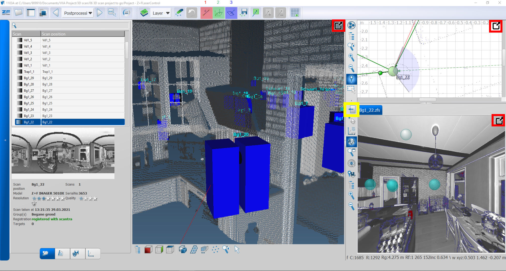
Figure 14 Plan view and 3D-, 360o view from a viewpoint in Z+FlaserControl
Every bullet (shown in the colour green) on the plan view (top right window in Figure 14) is a viewpoint. Double-clickingon a bullet opens the 360o view (bottom right window in Figure 14). All the views can be maximized or minimised by clicking in the buttons shown within the red boxes (in Figure 14). The 360o viewpoint can close by clicking the yellow box (in Figure 14). Keep in mind that opening too many 360o views at the same time will significantly slow down the viewer.
It is possible to measure distances within the 360o view in the Z+Flaser control. The measurements appear both on the 360o and the 3D view. Measuring distances can be done in three ways:
Measure option (button 1 shown in red in Figure 14): the distance between two points is calculated. This distance measuring tool can recognize planes. It is appropriate especially for measuring distances across surfaces.
Width and height measurement option (button 2 shown in green in Figure 14): The measurement is aligned with the horizontal or vertical axis and is suitable for measuring the height or width of a room (distance between floors or walls, measurements of openings etc).
Measure distance from point to plane option (button 3 shown in blue in Figure 14): This tool can be used to measure the distance between a point and a sloped surface, like a roof.
A live demonstration of Z+FlaserControl can be found at the recording of the VIIA knowledge sharing meeting in 16/6/2021 (51st minute till the end of the recording). This is the LINK to the recording.
Autodesk ReCap
Other 3D scans are saved in .rcp files. Such files can be opened with Autodesk ReCap. The installation of the software can be requested through the ICT order portal.
The .rcp file along with other files are commonly saved in a compressed folder. The folder can be located in one of the subfolders within folder 01 Bureaustudie or 02 Opname on BOX. It depends whether the inspection was done by a third party or VIIA, respectively. You should save a copy of the compressed folder locally to your computer and then extract the content.
Double-clicking the .rcp file, the 3D scan opens in Autodesk ReCap. A screenshot of the GUI start screen is shown in Figure 15. The 3D view of the object appears in the start screen.
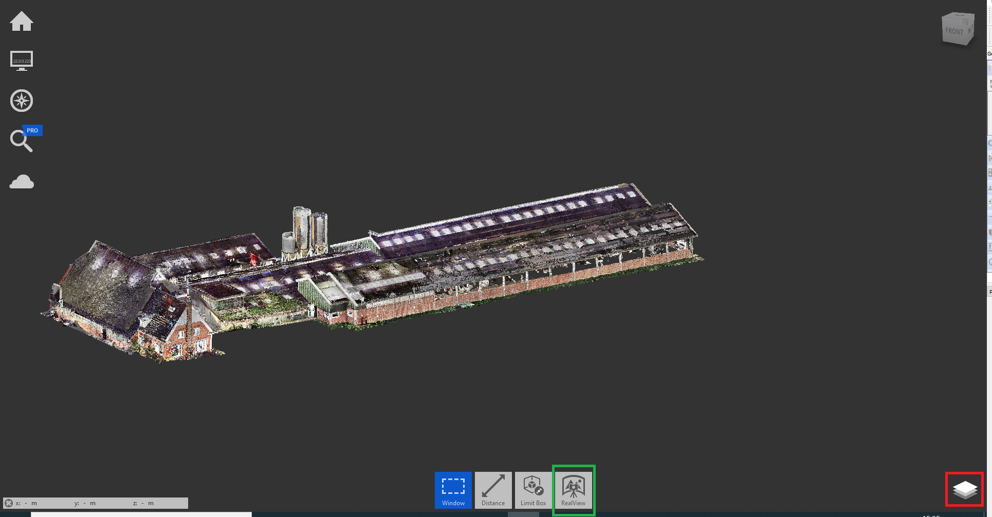
Figure 15 Start screen of Autodesk ReCap.
Note
When working at the office and using the monitor as your main screen, it is possible that you encounter a graphics related issue that prevents launching Autodesk ReCap. In this case specify your laptop screen as your main screen and restart the software.
Clicking on the project navigator (indicated within the red box in the bottom east corner of the start screen shown in Figure 15), all the scan locations (viewpoints) appear in a list (see Figure 16). It is possible to zoom in on each scan location as well as to hide/show them.
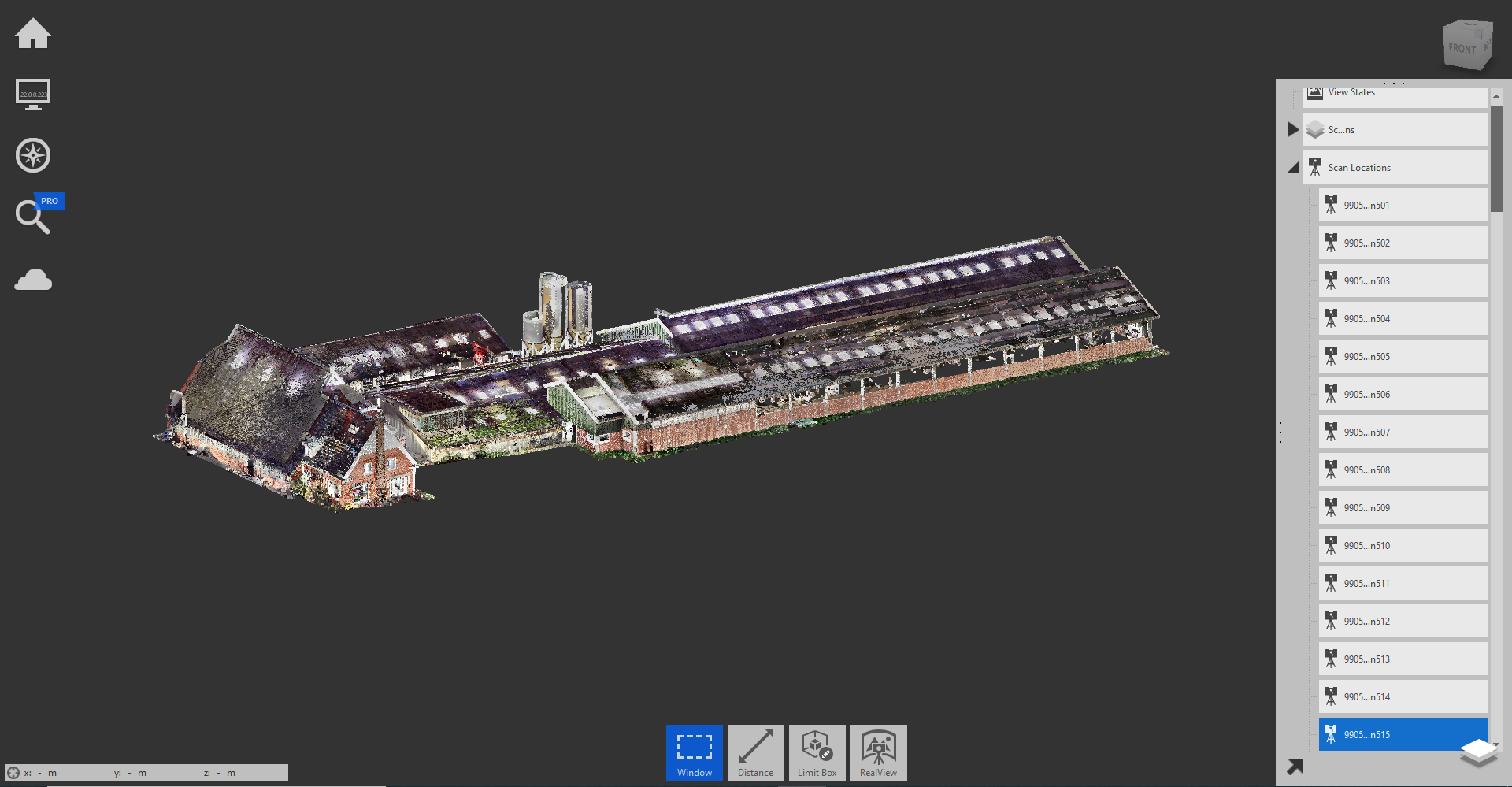
Figure 16 Start screen of Autodesk ReCap with the project navigator extended.
Clicking on the RealView button (indicated within the green box in the bottom edge of the start screen shown in Figure 15) the 360o view from a scan location opens (see Figure 17). A minimised window with a plan view of the object is present on the top right corner of the screen.
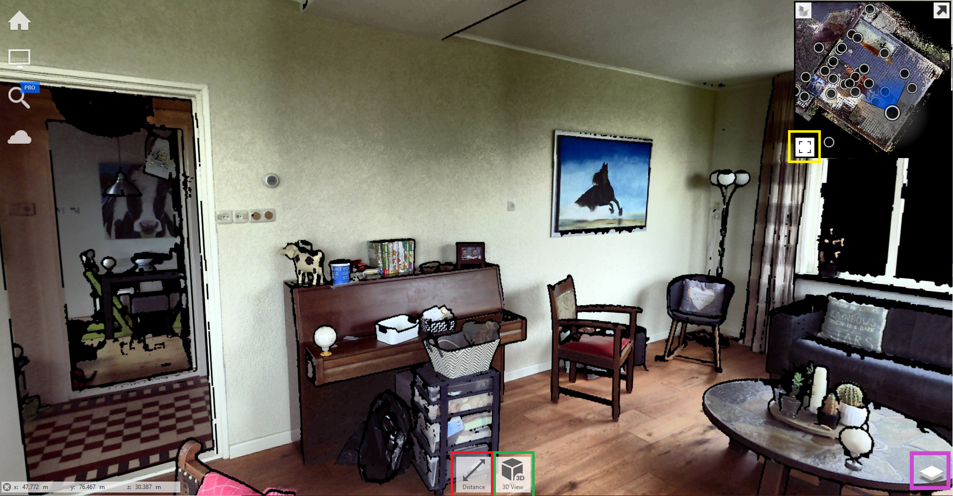
Figure 17 360o view from a scan location and minimized plan view.
It is possible to maximize the plan view by clicking the expand view button, which is indicated within the yellow box in Figure 17. The maximized plan view is shown in Figure 8. The black bullets are the scan locations. Clicking on each scan location the relevant 360o view can be viewed. The window with the 360o view can be maximised again by clicking the expand view button, which is indicated within the yellow box in Figure 18. Changing the scan location and, hence, the 360o view can also be done by opening the project navigator (indicated within the purple box in the bottom east corner of Figure 17) and selecting one scan location from the list. It is possible to change the viewing angle from the scan location by moving the mouse while keeping the right button or the scroll wheel pressed. The viewing angle is updated in the plan view.
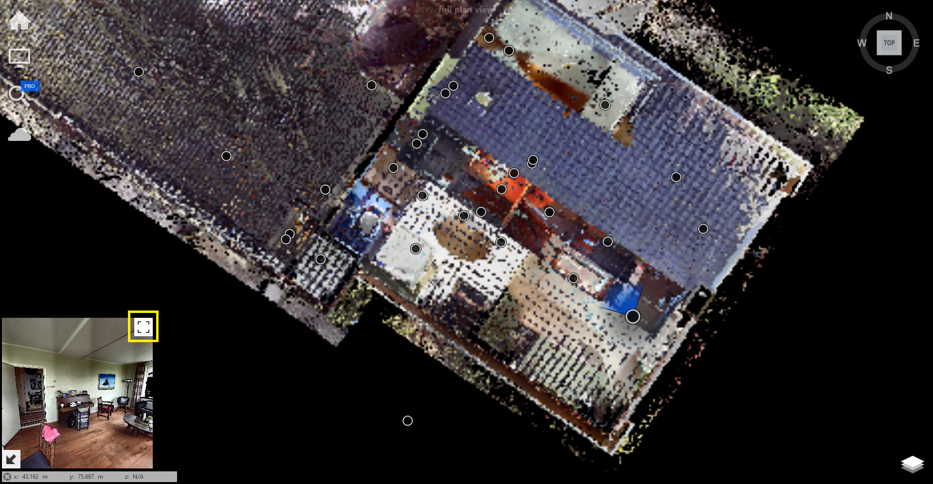
Figure 18 Plan view and minimized 360o view from a scan location.
Distances can be measured in this case as well. By clicking on the left button on the bottom edge of the screen (indicated within the red box in Figure 17), you can choose to measure a distance or add a note to a point. The distance tool can be used to create freehand or orthogonal measurements along the global axes. Additionally, the tool recognizes planes. The measurements are visible in the 360o view as well as the 3D view.
To return to the 3D view you can click on the right button on the bottom edge (indicated within the green box in Figure 17). By zooming out, the whole object becomes visible again in the 3D view.
An Autodesk ReCap demo video is available in the LINK.