4. Phase 2: Expected building behaviour
After phase 1 of reading and inspection, the engineer proceeds to outline the expected behaviour of both PSSEs and NSCEs in the event of an earthquake. This involves selecting critical elements with respect to governing failure mechanisms. Common failure mechanisms for buildings assessed in the Groningen region are:
Failure of connections
Failure of diaphragm action of floors and roofs
Out-of-plane failure of walls (stabilizing elements)
In-plane failure of walls (stabilizing elements)
Foundation failure
Critical elements are structural elements or connections that have geometric and material properties that render them with low capacity for a certain failure mechanism. This implies that for each failure mechanism, one or more critical elements need to be identified. The engineer then elaborates the reasons why the critical elements are expected to fail or pass under the given loading conditions.
The expectations and selection of critical elements requires knowledge of structural behaviour. This section elaborates some of the expected behaviour of elements and factors that contribute to the required capacity of elements.
Th expectations of the engineer need to be discussed with the Lead engineer and technical master to move forward with the assessment.
4.1. Connection behaviour
The major role of connections is to guarantee the structural integrity of the building by transferring loads between structural elements. Factors that govern the behaviour of connections are:
Strength and deformation capacity of the connecting element (e.g. wall plates, nails, anchors, mortar)
Load transferred between the connected elements
Existing condition of the connection
Although all connections serve a purpose, some connections have higher significance due to the extent of damage that can occur if they were to fail. For example when a connection fails it might change a 1-way spanning wall to a freestanding wall, severely reducing the OOP capacity of the wall.
Section 9.4.6 “Connections” of the UPR document [RA1] states the following: Results from existing FEM models, which have been assessed with NLTH have revealed that connections rarely exceed the acceptance criteria. Connections are therefore only considered critical in specific cases or when information from the inspection report shows damage that can alter their capacity or functionality.
Examples of points of focus for some structural elements and their connections are given below.
4.1.1. Roof-Wall Connection
Identify the load path from the roof to the wall for horizontal and vertical loads. See if there are any damages that can hinder the necessary transfer of loads in both static and seismic conditions.
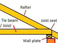
Figure 4.14 Connection detail between roof structure and wall.
4.1.2. Roof Tension Tie Connection
Failure of the connection of tension tie elements leads to (excessive) horizontal forces acting on walls or other stabilizing elements. Example of tension tie elements can be tie beams joined to roof rafters. Thus, identify these connection points and verify if strengthening is necessary
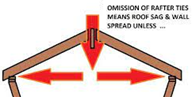
Figure 4.15 Connection of tension tie to wall plate.
4.1.3. Roof-Floor Connection
In certain cases where the attic floor is joined with the roof, this connection enables the diaphragm action of the attic floor to be extended through the roof (red area in the figure below).
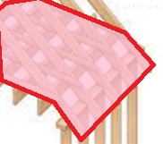
Figure 4.16 Connection of floor to roof
4.1.4. Timber Elements Connection
There are various types of connections for timber structures (timber to timber). Timber connections that are in good condition transfer forces in the intended manner. This guarantees that the elements will behave as they are designed.
4.1.5. Wall-Floor connections
Floors can be connected to walls in different ways. The figure below shows some examples of connections between walls and floors. The rigidity of the connection between the floor and wall differs based on the connection type. For example, connections of floor beams embedded inside a wall have higher moment resistance compared to beams simply supported by corbels.
4.2. Diaphragm behaviour
Diaphragm elements or in-plane shear load carrying elements are important in laterally loaded structures as they transfer loads between load carrying elements and help increase the collective capacity of the building. If the major lateral load carrying elements are shear walls, then the floor or roof on top of these walls carry and distribute forces to the shear walls. In the process, they are loaded mainly by in-plane shear forces. Diaphragm elements can be rigid (e.g. concrete floors) or flexible (e.g. timber floors). A more extensive explanation of diaphragm behaviour of floors and roofs is elaborated in the SLAMA Protocol in section this section.
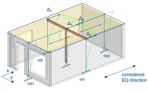
Figure 4.17 Deformation of laterally loaded walls and frames to illustrate the use of diaphragm elements.
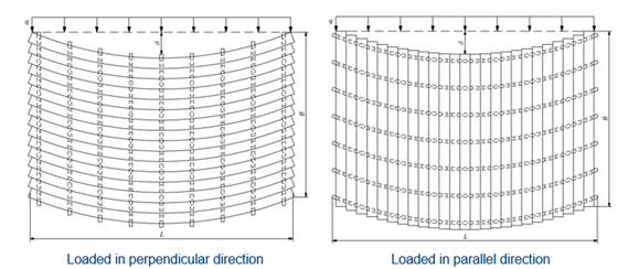
Figure 4.18 Effect of beam layout in diaphragm behaviour.
4.2.1. Floor diaphragm behaviour
The parameters to determine the floor behaviour are listed below:
Floor material;
Dimension parallel to the span direction;
Dimension perpendicular to the span direction;
Connection parallel to the span direction;
Connection perpendicular to the span direction;
Presence of large openings (e.g: staircases);
Continuity of the diaphragm between different building areas
4.2.2. Roof diaphragm behaviour
The parameters to determine the roof behaviour are listed below:
Roof material
Dimension parallel to the span direction;
Dimension perpendicular to the span direction;
Connection parallel to the span direction;
Connection perpendicular to the span direction;
Presence of large openings (dormers/windows);
Presence of additional beam along the edges of the roof;
Roof type
4.3. Floor behaviour
Next to the assessment of the diaphragm behaviour of the floors, placement of the floor in the structure is also important to assess. For example, the diaphragm action in floors at ground floor level is negligible under seismic loading for objects within the scope of the use of the Reference Approach Method. Next to that, based on the research “Vallen van hoogte” from the gezondheidsraad, falling from a height of up to 2 meters has roughly a 1% lethality. The Near Collapse situation corresponds to a 10% lethality according to F.6.2 of the NPR9998. Therefore, falling from heights up to 2 meters is within the accepted lethality in the Near Collapse situation and is deemed acceptable.Therefore, the floors at ground floor level are not assessed.
4.4. Roof behaviour
The analysis of the roof includes the assessment of the diaphragm action, roof connections, stability system, roof structure and transfer mechanisms of the loads carried by the roof.
This section focuses on the stability system and structure of the roof. The behaviour of the roof connections and diaphragm action is already discussed in section 4.1 and section 4.2 respectively. A roof is chosen as a critical element once all the relevant aspects of the system have been analyzed together.
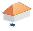
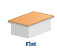
The stability system is related to the roof type. The figure below shows some of these types: each one provides a different load transfer mechanism and requires the check of different critical components.
Table 4.1 - Roof types and critical stability and structural components according to each type |
||||
|---|---|---|---|---|
Group A |
||||

|

|

|

|
|
Group B |
||||

|
|
|
||
Group C |
||||
|

|

|
|
|
Group D |
||||
|
|
|||
For example, roofs with gables are critical due to the acting horizontal mass that the gable transfers to the roof system. On the other hand, the presence of a tying (tension) element is important for roofs in groups A and B (with sloping sides only in one direction). Besides providing stability to the system, the tying elements prevents the roof to push the lateral walls in the out-of-plane.
The roof structure refers to the presence of main trusses or frames, rafters and purlins which provide support and give stability. These elements must provide a clear load transfer path; if there is any damage either in the elements or in the connections then the state of the system might not be sufficient to resist the seismic actions (even in the presence of diaphragm with enough in-plane shear capacity). Renovation works might also affect the load transfer mechanism of the roof structure.
4.5. Out-of-plane behaviour
The out-of-plane behaviour of walls can be classified as one-way or two-way spanning. It is influenced by several parameters as mentioned below:
Wall geometry;
Wall material;
Lateral supports distance;
Interlocking with walls in the orthogonal direction
First floor material;
First floor level;
Connection at first floor level;
Roof material;
Roof typology;
Roof level;
Connection at roof level;
Openings area with respect to the total wall area.
Three parameters are explained below.
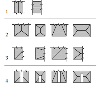
Figure 4.19 Idealised Crack pattern for masonry walls shown in NPR9998:2020[3]. (1) One-way spanning walls; (2) Two-way spanning walls: supported in both sides; (3) Two-way spanning walls: supported in one side; (4) Two-way spanning walls: supported in both sides with openings.
Boundary conditions:
The stiffness of the boundary conditions determines the out-of-plane deformation of walls. This influences the deformation and crack pattern of walls. The type of the boundary condition is governed by the stiffness of the adjoining elements and the connection. Examples can be stiffness of diaphragm elements and stiffness of perpendicular walls. The type of the boundary condition determines if the wall will be one-way spanning or two-way spanning.
Geometry of wall (thickness, length, height, size of openings):
The thickness of the wall influences the bending capacity of the wall.
The length and height of the wall determine the extent of the deformation of the wall as they determine the horizontal and vertical spanning length of the wall respectively. The size and shape of openings influence the out-of-plane deformation of walls as they introduce interruption of load path in the walls. As shown in Figure 4.8 the crack pattern due to out-of-plane deformation is also affected by the length of the wall as well as the size of openings in the wall.
Material of the wall: Material of the wall determines the bending capacity and weight of the wall.
4.6. In-plane behaviour
The first step in analysing the in-plane behaviour of the structure is to find the critical element(s): this section provides the workflow for this selection. The assessment method after the selection of the critical elements(s) depends on the type of analysis, NLTH or NLPO. Figure 2.1 presents the general workflow for the in-plane behaviour. Guidelines and examples for the assessment of the in-plane critical elements is provided in section 9.
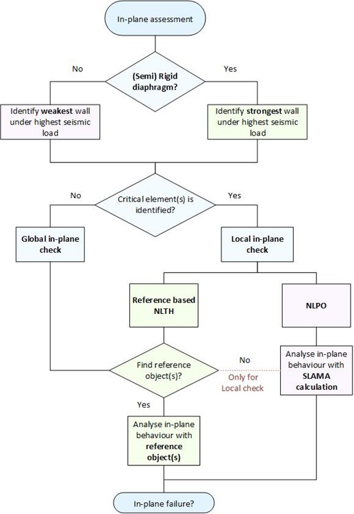
Figure 4.20 In-plane general workflow.
The global in-plane behaviour is assessed by identifying the critical local element. This is done by analysing the vertical and horizontal (x and y) load paths in the building. Usually, the direction with the least meters of wall is critical, since the loading in this direction is the highest.
The first step in selecting the critical element(s) is to identify the behaviour of the diaphragm. In buildings with (semi) rigid diaphragms the most seismic load is usually taken by the strongest element in the system: the critical element must be strong enough to resist the forces (strength criteria). Concrete floors behave as rigid diaphragms.
On the other hand, for buildings with flexible diaphragms the seismic load is distributed depending on the tributary area of each wall. Therefore, the focus now is the weakest element of the system subjected to the highest seismic load (activated mass pushing the critical element). The critical element(s) must be flexible enough to allow the occurring deformation (deformation criteria). Timbers floors with planks is an example of this type of diaphragm.
The critical elements can be selected based on the following criteria:
Stiffness: wall thickness, wall material, wall L/H ratio (slenderness ratio?), presence of openings, combination of wide and slender piers, expected stiff or ductile behaviour
Mass: tributary area from first floor and roof (flexible diaphragms), perpendicular walls
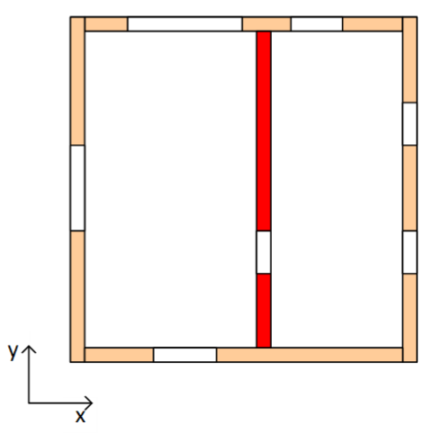
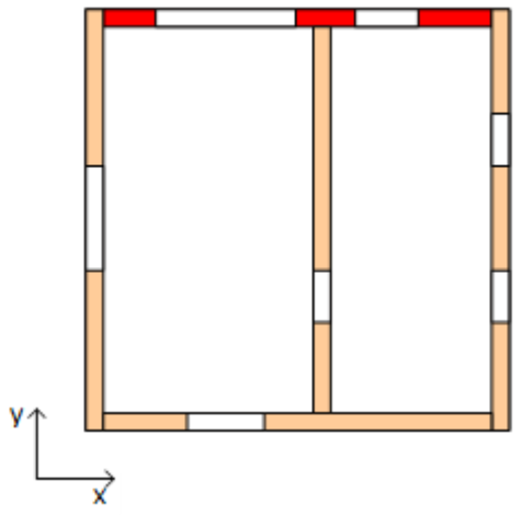
Table 4.2 - Diaphragms |
|
|---|---|
(Semi) Rigid diaphragms Strongest element |
(Semi) Flexible diaphragms Weakest element |
|
|
The elements in the surroundings of the wall can be classify either as mass acting on the wall as seismic load, or mass acting on the wall as both overburden load and seismic load. Only a significant value of overburden load helps in the in-plane behaviour of the wall.
For the NLTH-REF approach it is also possible to assess the global behaviour directly, if a suitable reference object can be found that has a similar distribution of walls, mass, diaphragm and PGA. For NLPO it is possible to analyse the global behaviour with a full SLaMA, however this is not advised since it is significantly more work.
4.7. Foundation behaviour
For shallow foundations, the geotechnical engineer performs assessment of the foundation if certain conditions are present. These conditions are shown in Figure 4.7 and Figure 4.8. The structural engineer is responsible to check if the conditions necessary for a geotechnical assessment are met. This is done according to Figure 4.8.
For deep (pile) foundations, geotechnical engineer always needs to perform an assessment of the foundation. For pile foundation the engineer delivers a few characteristic pile properties (bending moment capacity, shear capacity and bending stiffness). An excel tool can be used to calculate these properties, which requires reinforcement, prestressing and pile dimension information. If no information is available, assumptions in consultation with LE can be made.
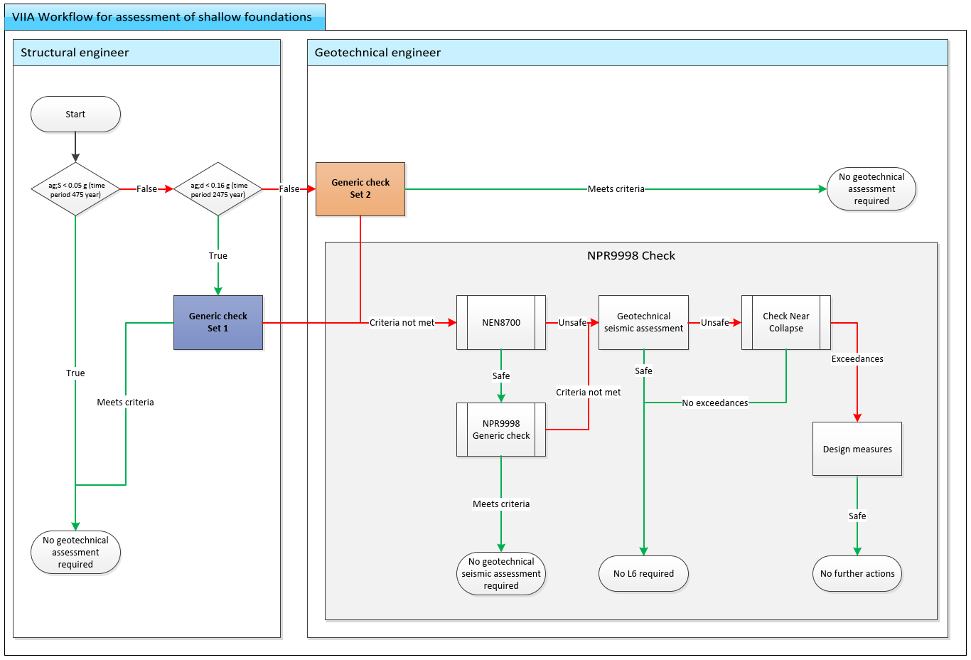
Figure 4.21 Flowchart of geotechnical assessment criteria for shallow foundations.
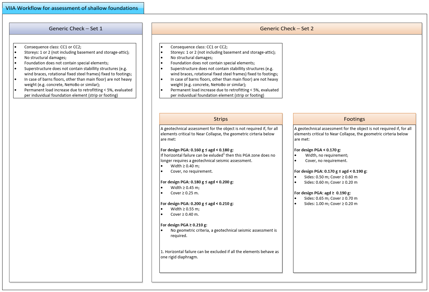
Figure 4.22 Checks to be performed by structural engineer (blue) and geotechnical engineer(orange) for shallow foundations.
Check additional guidelines in: this section.
4.8. NSCE assessment
A detailed explanation about the NSCE’s assessment is given in section 9.4.7 ‘NSCE’ of the UPR document [RA1].
4.8.1. Chimneys
For the assessment of chimneys, the generic risk assessment as described in section 9.3.2 of the UPR document [RA1] can be used. For chimneys that can fall on an escape route or onto public spaces, NSCE category 4 should be used for the generic risk assessment. A return period of 475 years is used for the demand. For chimneys that do not fall on an escape route or onto public spaces, NSCE category 2 or 3 can be used.
If a chimney does not pass with the generic risk assessment, Annex H of the NPR 2020 [RA3] can be used. Based on formula H5.a from the NPR 2020 [3], the upper bound for the demand of a chimney would be around 1.40g, given that the PGA would be less than 0.25g. Generally, the PGA in Groningen is less than 0.25g, therefore the upper bound for the demand is deemed reasonable. Based on figure H.5.4 from the NPR 2020 [RA3], the resistance of a chimney would be about 1.40g, given that the slenderness of a chimney is less than 3. In reality, the slenderness of chimneys is often around 1 to 3, thus it can be said that a resistance of 1.40g is a lower bound. Based on the upper bound for the demand of 1.40g and the lower bound for the resistance of 1.40g, it can be said that chimneys are expected to meet the requirement. This statement only holds if the chimney is well supported (by a proper chimney duct) and if the chimney is supported by the roof (so that the chimney height is only the part above the roof).
If the chimney is no longer properly supported (no chimney duct or chimney duct has been replaced by a lightweight one in the past), it is recommended to replace the chimney by a lightweight chimney. If the chimney duct is replaced by a lightweight duct, it is recommended to also replace the chimney with a lightweight chimney.
4.8.2. Outer leaves
Non-load bearing outer leaves are assessed as an NSCE. They can be checked using a reference building, the L4-sheet or engineering judgment. If the outer leaf is expected to fail, an L4-D measure (application of cavity ties) is applied on the area of the outer leaf that needs strengthening. Only the areas within 1.00 m of an escape route or outer leaves that can fall on an escape route require strengthening. If an L4-D measure is applied, the wall needs to be checked again using the L4-sheet. In this sheet, both leaves are considered since they are now connected with cavity ties. This check is only required if it is believed that the cavity wall has one-way spanning behaviour, otherwise the L4-sheet is too conservative. If perpendicular walls are connected to the inner leaf, the check may be omitted. This is done in consultation with the lead engineer.
In the past, the L4-D measure was sometimes applied as a row at the top of the wall. This is only done if the outer leaf needs to be connected to the floor. A row of cavity ties at the top edge of the cavity wall is no longer applied to improve the out-of-plane behaviour of the outer leaf.
Technical kick-off is described in the next page: ‘Phase 3’.