4. Phase 3 - Flexbase model phase
In this phase complexity is added to the FEM model by incorporating Soil-Structure Interaction (SSI) considerations. Here, the boundary conditions are applied with a non-linear behaviour (or more specific an interface is applied between the foundation elements and the fixed supports or base).
In this section, the so called flexbase model condition refers to one of the SSI analysis procedures where the the SSI effects are simplified to spring elements at the foundation level which add certain flexibility to this boundary condition if compared with the infinite stiff one. For NLTH, damping dashpot may be used as well.
The following image shows the flexbase process which follows a similar one that the fixed base condition.
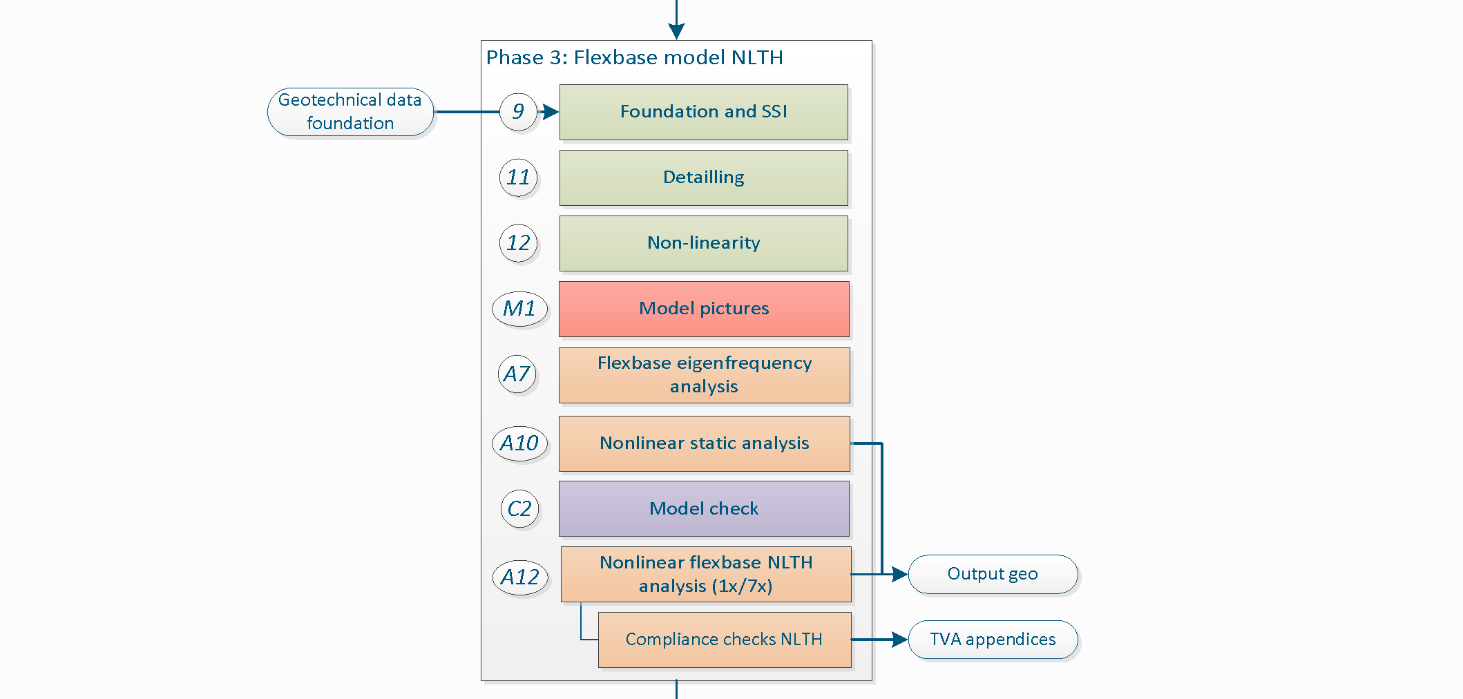
Figure 4.1 Phase 3 - Flexbase model.
Note
For each phase various steps need to be performed. The number assigned at the left side of the step description is used to identify the step and to link it with the corresponding item in the python-script. It is not necessary to perform the steps in the presented order. However all steps in a certain phase should be completely finished before moving forward to the next phase.
4.1. Step 8: Apply the boundary conditions and base motions for flexbase to the model
In this step, the initial fixed base foundation conditions are changed to consider the soil-foundation interaction. This change is relevant to supplement the fixed base assessment since to use a flexbase condition release the foundation elements at the bottom of the structure to interact with the structure so that their characteristics are now relevant to the analysis. For example, to consider the flexbase conditions at the foundation may trigger a diverse failure mechanism for the structure when the foundation elements are weak/flexible (as shown in the figure underneath). Is case of masonry foundation, the connectivity in between elements may not be guarantee so it is recommended to use only the fixed base condition, usually this is more conservative than to incorporate the flexbase considerations since this flexibility allows the structure to accommodate the seismic action between structural components, which may not be realistic if the connections are not good.
For modelling of the boundary conditions in general refer to Step 7: Apply the boundary conditions and base motions for fixed base to the model, where the fixed base is described.
For flexbase condition the parameters are calculated according the terrain conditions as reported by the geotechnical advisor. For estimating the linear spring values, the geotechnical engineer requires not only the geotechnical soil investigation data but also the data output of the static analysis (according to the BoD) and the structural capacity of the shallow foundation and/or the of the foundation piles. The later, provided by the structural engineer.
When you create a shallow foundation and/or piles in your model, after creating the fixed base foundation. The fixed base shapes will be removed first.
4.1.1. Shallow foundation
The shallow foundation in flexbase analysis is modelled with a boundary interface. This interface is modelled with a user supplied material-model. The following figure shows the relation between the dat-file and the material model in DIANA. The process of handling the data in the dat-file has been automated. The dat-file is not required anymore, the data in it still is.
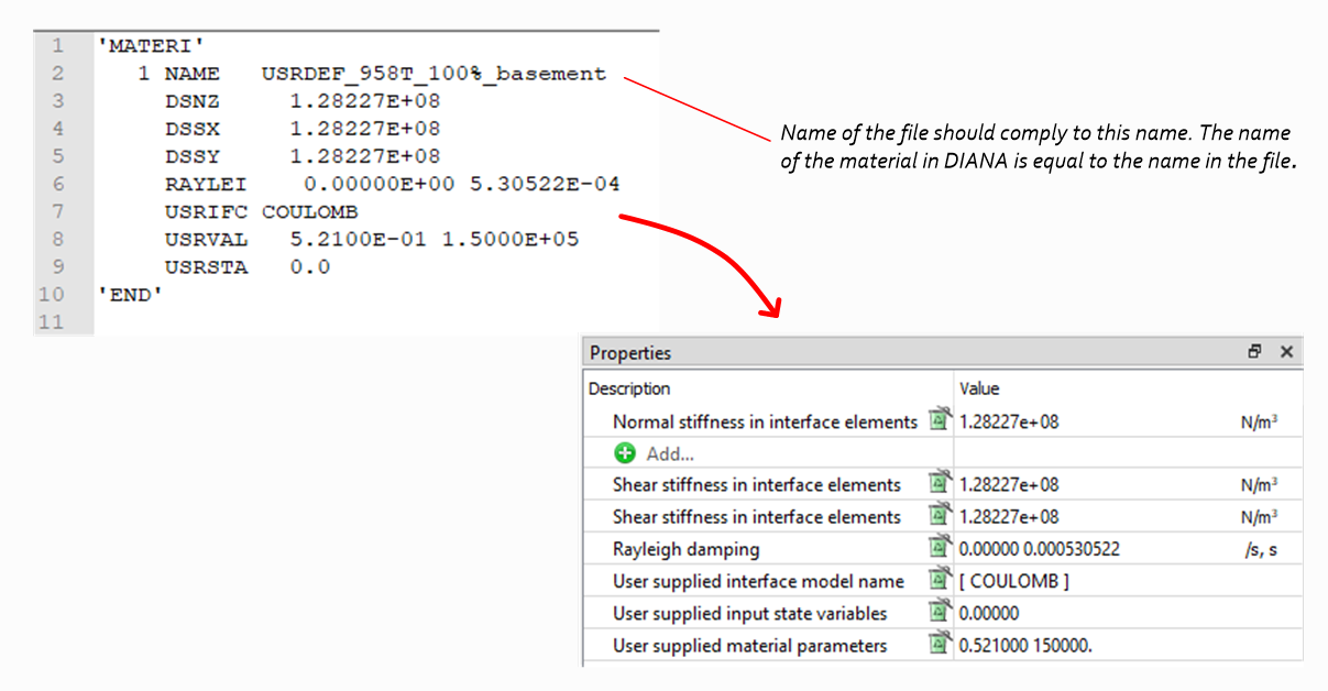
Figure 4.2 Dat-file from geotechnical advisor converted in DIANA.
The values for this user supplied subroutine that model the soil-structure interaction (SSI) are calculated from default values or provided by the geotechnical advisor. The procedure ‘FlexBaseGlobal’ should be followed if the geotechnical assessment is not performed, else use the ‘FlexBaseFinal’ procedure.
Warning
Before creating the flexbase shallow foundation it is required to finalise the fixed base model phase and perform the A1 analysis. Finalise the A1 in the progress report of phase 2 in MYVIIA.
4.1.1.1. Geotechnical assessment not performed (FlexBaseGlobal)
When the geotechnical assessment is not performed default values are used for the flexbase modelling of the shallow foundation. The default values are calculated based on the weight of the building only (no input required from the geotechnical advisor). Model the shallow foundation supports for flexbase with:
project.viia_create_supports(support_type='FlexBaseGlobal')
The values for the linear elastic stiffnesses are based on the weight of the building from A1 analysis. It is calculated that the spring value will have an eigenfrequency of 30Hz. It is assumed that the foundation doesn not fail, hence capacities are set to a high value.
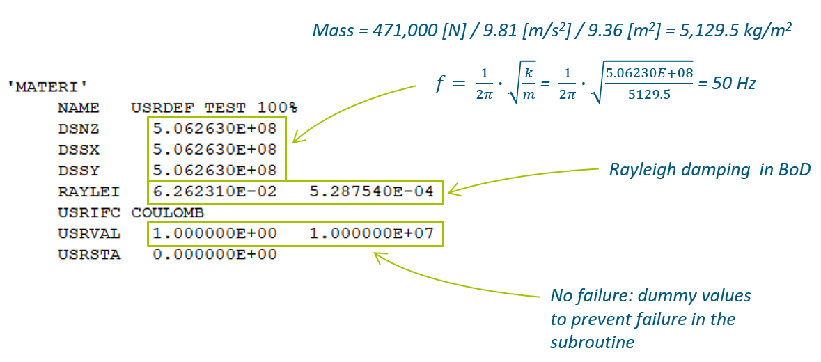
Figure 4.3 Material properties provided for the subroutine for shallow foundations, standard values.
4.1.1.2. Geotechnical assessment is performed (FlexBaseFinal)
In this case the geotechnical advisor provides the input for the parameters of the shallow foundation in MYVIIA. The properties for the shallow foundation provided by the geotechnical engineer contain the linear elastic stiffnesses and the capacities.
Once the A1 analysis is performed and the progress is updated (finalise the A1 analysis), the geotechnical advisor can start the assessment with the data on MYVIIA. You can and should check the values you have calculated. There might be different materials defined for different foundation strips. The geotechnical advisor is responsible for the selection where to apply which material parameters for the ‘FlexBaseFinal’. Always contact the geotechnical advisor in this process. The same 30Hz cut-off value for the eigenfrequency is used to prevent base-isolation behaviour.
The function viia_create_supports() with the argument ‘FlexBaseFinal’, provides
supports in the model including an interface attached to the supported surfaces (see explanation in Step 8: Apply the boundary conditions and base motions for flexbase to the model).
In case there is only one material provided by the geotechnical advisor, you can simply:
project.viia_create_supports(support_type='FlexBaseFinal')
Warning
For proper behaviour of the boundary interfaces for the shallow foundation, the local axis of the supported surface (fstrip or floor) should be pointing downwards. Also check if all local x- and y- axes of the boundary interface are pointing in the same global direction.
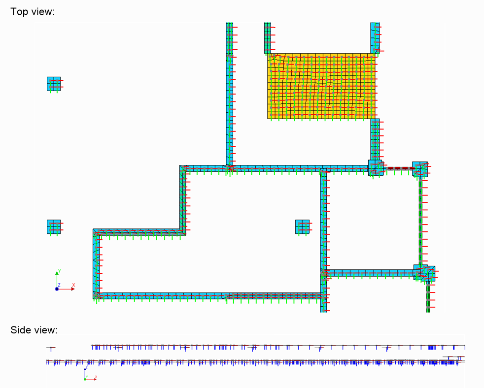
Figure 4.4 Checking the local axes for the boundary interfaces in DIANA.
If required different materials can be applied to the model on different parts of the foundation. Note that all the supported surfaces should be in the values of this dictionary.
Warning
The procedure to get different materials from MYVIIA is not available yet. Use the current procedure with different dat-files as described here.
project.viia_create_supports(
    support_type='FlexBaseFinal',
    additional_supported_shapes=['N0-VLOEREN-LIN-BETON-150-1'],
    material_dictionary={
        'USRDEF_XXXX_100%.dat': [fstrip for fstrip in project.collections.fstrips],
        'USRDEF_XXXX_100%_floor.dat': ['N0-VLOEREN-LIN-BETON-150-1']})
In this example all foundation strips behave based on material USRDEF_XXXX_100% and the ground floor bahaves based on the material model defined in USRDEF_XXXX_100%_floor. In thic case it is important that the name of the file complies to the name in the file to prevent confusion.
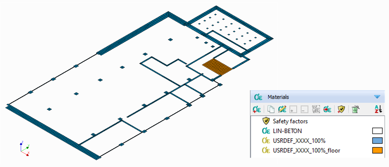
Figure 4.5 Application of multiple materials for shallow foundation in flexbase analyses.
4.1.2. Pile foundation
The pile workflow depends on the availability of information on the pile and the pileplan. In the kick-off meeting it is decided if the geotechnical assessment is to be performed. For this decision it is relevant to collect all information available and check the PGA.
4.1.2.1. Geotechnical assessment not performed (FlexBaseGlobal)
When information is lacking or the geotechnical assessment is not performed, the pile foundation will not be modelled, a shallow foundation interface with default properties is applied instead. We prefer not to model piles if we don’t know where they are located, or if we don’t have a proper insight in the pile properties.
Follow the workflow of Geotechnical assessment not performed (FlexBaseGlobal).
4.1.2.2. Geotechnical assessment is performed (FlexBaseFinal)
The flexbase piles follow a similar approach as in the fixed base (see Step 7: Apply the boundary conditions and base motions for fixed base to the model). Now the piles are generated
with nonlinear springs and nonlinear beam elements. The values for the nonlinearity are determined by the geotechnical
engineer. The pile procedure described in ‘pile workflow’, should now be finished. The
structural engineer calculates the structural properties, which are used in the geotechnical analysis. The results of
this analysis are shared by the geotechnical advisor on MYVIIA. The function to generate the piles
(viia_create_piles()) retrieves all required values from MYVIIA.
The flexbase pile is modelled with 5 springs (5 degrees of freedom) which are located between the column shape (Huan-beam) and the foundation beam (fstrip). The behaviour of the springs is modelled with a user supplied subroutine spring material model. The beam element with a total strain crack concrete material model with reinforcement steel.
The following code will remove previously created piles, collect data from MYVIIA and generate the piles. The same function is used, but the input for the support-type should be provided, use ‘FlexBaseFinal’ for this. The ‘FlexBaseGlobal’ setting is not available for pile foundations.
pile_coord = [[1.0, 0.3]]
project.viia_create_piles(coordinates=pile_coord, support_type='FlexBaseFinal', pile_group='A')
Refer to step 8 of the fixed base model and apply the same approach if you have multiple pile-groups.
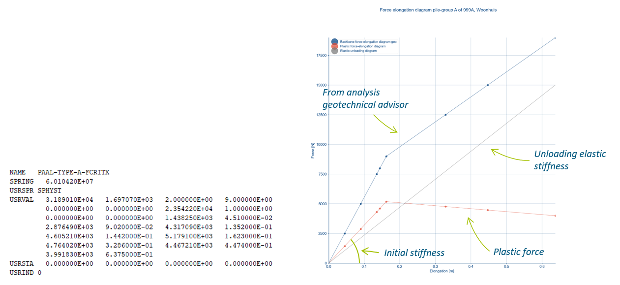
Figure 4.6 Material properties provided for the subroutine for pile foundations, values derived with geotechnical input.
4.1.3. Mixed foundation
Both the procedures for shallow foundation and pile foundations should be followed. The shapes in Fstrip class (the foundation beams and foundation strips) should be excluded from the shallow foundation function when they are located on top of the piles.
4.2. Step 9: Connections
In this step, the connections between the various building components are applied. For NLTH, usually connections are to be modelled, when the connection influences the behaviour of the structure. Between the various building components the connections are modelled by means of hinges, rigid (fixed) connections, or interfaces; as described in Chapter 7 of the Basis of Design (NL: Uitgangspuntenrapport). Or, if it concerns a strengthening measure, according to Chapter 8 of the BoD.
Starting point for applying the connections to your model is that all shapes are connecting, refer to
Step 6: Apply Non-Seismic Loads where all shapes are connected using _viia_connect_all_shapes()
function. The step for applying connections should be first use the auto functions:
project.viia_auto_interfaces()
project.viia_auto_hinges()
Once these functions have been executed, check which connections are not properly modelled (use the tools available mentioned below in the Mesh-check section). When there are connections to be added separately, use the following functions. But only to extend on the auto created connections.
project.viia_create_connection(
    source=project.viia_get('walls', id=5), target=project.viia_get('floors', id=1), detail='D2.01')
When applying connections, make sure to add complexity to the model in small steps. Apply some connections and run your model before you apply the next set of changes or additions to the connections. In general there are functions available to apply connections automatically and then for all special cases, or where auto functions do not provide the required connections in the model, apply specific connections. Further explanations on the workflow on how to apply connections can be found here: Common connection configurations.
4.2.1. Mesh-check
In this step it is useful to check the mesh, and the mesh results reviewed. This is similar to Step C1: Mesh check and is used to remove bugs from the model that may had occur when adding the details. During the mesh checking process it must be observed if DIANA created all interfaces defined in the ‘geometry’ (sometimes is not the case in DIANA). This can be visually checked by turning on the geometry and the mesh simultaneously when only the interfaces are shown.
The local axes of the interfaces must also be checked. For example the interfaces in the figure underneath the correct axis orientation is presented. The directions of the axes are defined for the details in the Basis of Design. The figure provides as well with an example presenting interfaces with the incorrect axis directions. This can be solved by changing the source and anchor point.
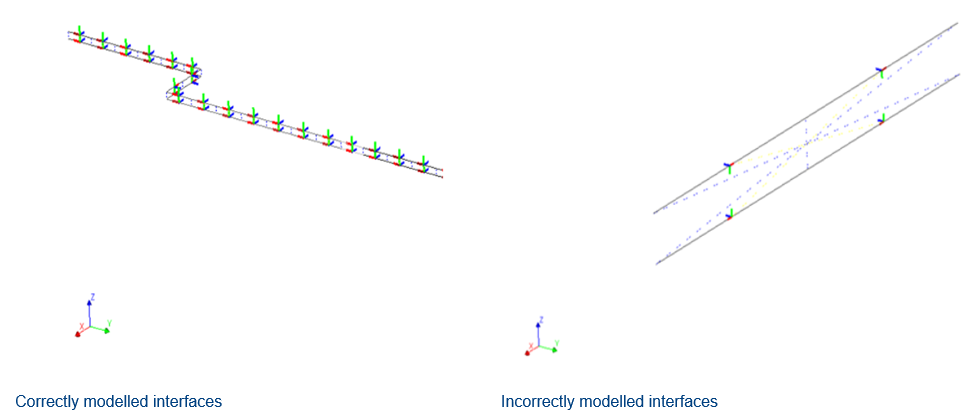
Figure 4.7 Local axes of interfaces in DIANA.
The mesh check pdf report contains warnings when there is an issue with tyings, disconnects and unites. In most cases the warnings are relevant and the user should attend to them. When you report often occurring warnings, please report those so the functionality in the viiaPackage can be improved.
When you want to gain insight on the shapes that connect to a certain shape, you can use the function
viia_shape_data_diana(). For example:
project.viia_shape_data_diana(view_shapes=['N1-WANDEN-LIN-MW-KLEI>1945-100-11'])
This generates a pdf-document in the ‘Mesh Check’ folder. Information is provided for the connecting shapes, the DIANA mesh-node IDS of the connections and a list of the Connections with their source and target shapes. The pdf-file looks like:
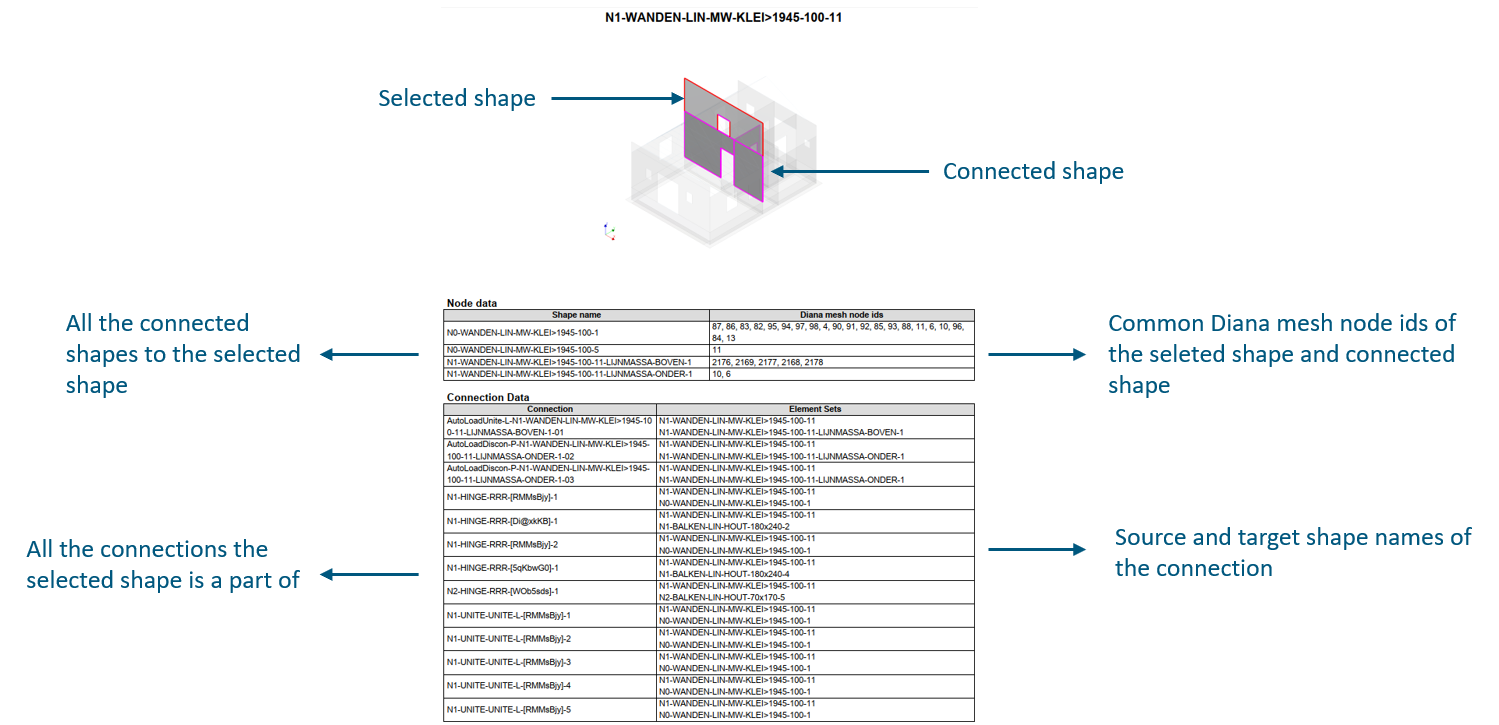
Figure 4.8 Example of the contents of the shape summary pdf report.
In some cases there might be warnings about connections. The following functionality is available to get insight in the
model at very specific mesh-nodes. Simply provide the 3D coordinate and the function
viia_node_data_diana() will generate a pdf report with all the shapes connected to
the point and all connections connected to the point with the information on source and target shapes.
project.viia_node_data_diana(view_nodes=[[0.2, 0.2, 2.7]])
This example results in the following report. On the left side of the picture a schematisation of the structure is added.
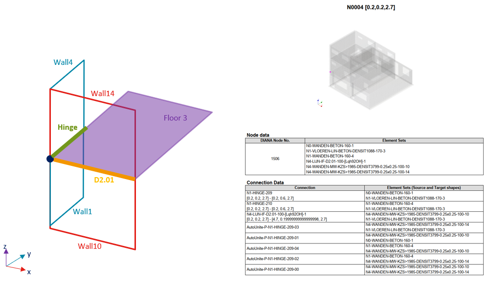
Figure 4.9 Example of the contents of the node summary pdf report.
4.3. Step A7: Flexbase eigenfrequency analysis
An eigenvalue analysis is performed to gain insight about the dynamic characteristics of the structures and to recognise mistakes/bugs that may show in this analysis.
Initially, run the analysis only with 10 eigenmodes. If elements of the building are, for example, not properly connected, they will present a very low natural frequency (below 5 Hz for one storey building, often due to low stiffness or not properly fixed elements, inspect the text file generated as in the figure below). Check both displacements and rotations. When such errors have been taken out from the eigenvalue analysis, you can proceed with more eigenmodes.
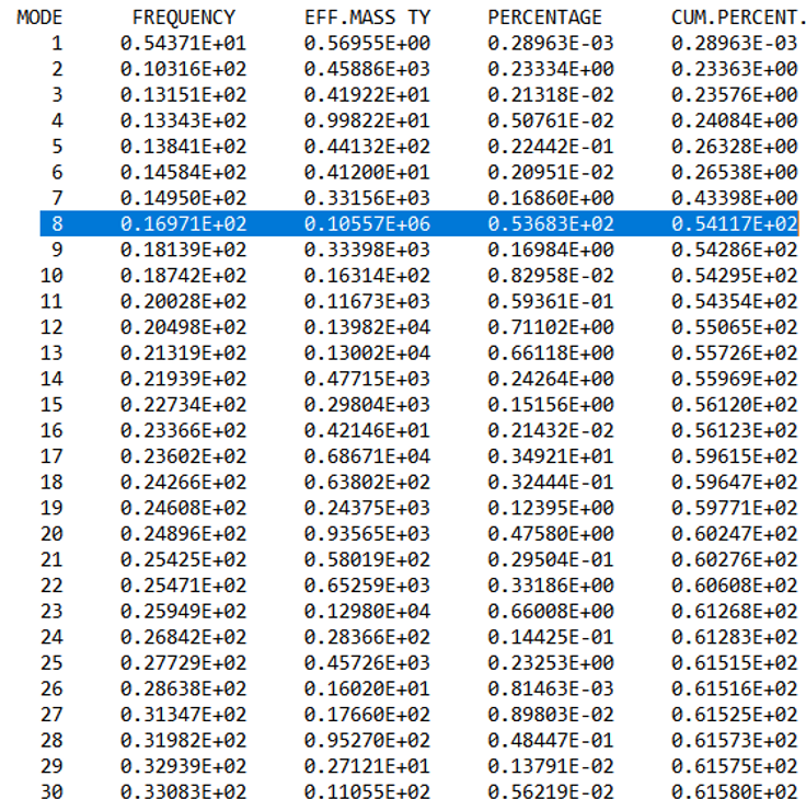
Figure 4.10 Example of the tabulated output-file the eigenfrequency analysis in DIANA. The percentage here refers to the mass participation and cum. percent. to the cumulative mass participation.
4.3.1. Analysis
By means of the following function, the eigenfrequency analysis can be applied to the structure. The preferred setting
for the run argument of viia_analysis() is ‘True’, indicating direct calculation
in DIANA. For DIANA you have to run mainscript in it in order to start the calculation. Initially set the number of
eigenmodes to 10. When finishing the complete phase the number of modes should have been set to 1000. The analysis
normally does not take to much time (in case not to many eigenfrequencies are requested).
project.viia_analysis(analysis_nr='A7', run=True, nmodes=1000)
4.3.2. Issues
If problems arise, the following steps can be taken:
When an analysis raises errors:
You can apply a frequency shift to examine the low frequency modes that occur, in most cases these elements are not connected properly.
For a better understanding of the dcf-file, read the how-to guide: How to DCF settings.
4.3.3. Results
The result handling is performed automatically when the analysis is created and directly ran in DIANA. If you need to do this (again) later you can use the reportscript with:
project.viia_results(analysis_nr='A7')
The following items should be checked:
4.3.4. Reporting
The figures of the governing eigenmodes, the graphs of the governing eigenmodes in the elastic response spectrum and the graph with the cumulative participating mass are to be included in Appendix C1. If strengthening is required, A7 should be re-executed and the updated figures should be included in the final version of Appendix C1.
Images of the governing Eigenmodes are created in the folder. An example is shown underneath. There are two images generated, one with and one without the roof shapes. The user should decide which picture is appropriate for the TVA report.
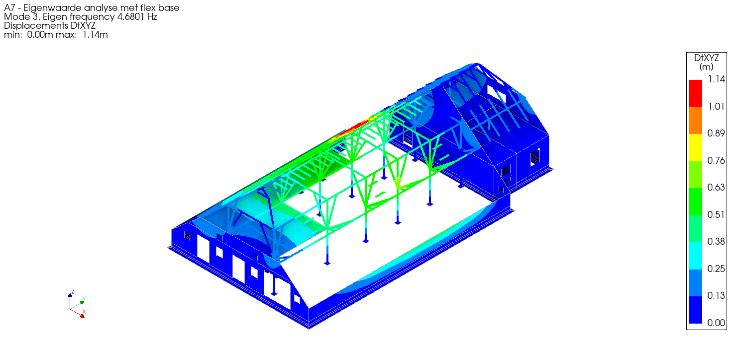
Figure 4.11 Example picture of the governing Eigenmode in x-direction without roof.
Note that the displacement mentioned is not relevant, the maximum displacement in x-direction is 1.0 (combined for 3 directions this value can be larger than 1).
The following graphs are generated and provide insight for the engineer in the overall behaviour of the structure.
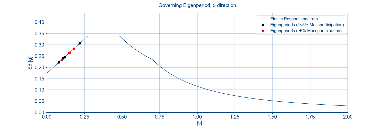
Figure 4.12 Example graph of the governing eigenmodes in the elastic response spectrum.
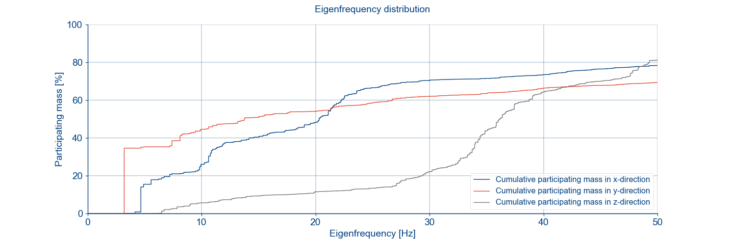
Figure 4.13 Example graph of the cumulative mass participation.
The results of the A7 analysis are part of the verification in the model check.
4.4. Step A10: Nonlinear static analysis
The purpose of this calculation is to test the behaviour of the structure with non-linear material properties and the connections. This analysis provides output for the geotechnical engineer. Even if the geotechnical assessment is not performed it is advised to perform this analysis.
4.4.1. Analysis
By means of the function viia_analysis() a non-linear static calculation can be
performed:
project.viia_analysis ('A10', run=True))
4.4.2. Issues
If problems arise from the result evaluated aspects just mentioned, observe the note mentioned above.
When an analysis converges:
Add result item for stresses to the analysis and analyse again to see where peak stresses occur.
For other possibilities regarding bug fixes see section Convergence
Analysis diverges:
If divergence occurs see section Divergence.
For a better understanding of the dcf-file, read the how-to guide: How to DCF settings.
4.4.3. Results
The result handling is performed automatically when the analysis is created and directly ran in DIANA with the function
viia_results().
The following items in A10 folder should be checked:
Interface stresses (tractions) (tensile stresses and compression, area)
4.4.4. Reporting
This step does not have to be reported. The results of the A10 analysis are part of the verification in the model check.
4.4.5. Geotechnical output
Note
Only required if geotechnical assessment is required.
The tabulated output 5A (shallow foundation) and 5B (piles) is required for the output that is sent to the geotechnical advisor. This output needs to be combined with the results from the A12 analysis of NLTH. How to generate the output for geo is explained in the how-to guide: How to create output for geo. This data is used for the geotechnical assessment.
Note
The weight of the building should already have been sent to the geotechnical engineer in step A1.
The data that needs to be provided in case of a shallow foundation:
Shallow foundation stress footprint.
Shallow foundation forces determined per strip, split for dead load and imposed loads. This data is auto collected in a json file.
The data to be provided in case of piles is:
Number of piles.
Plan view of the piles with the corresponding pile name, type and number.
Reaction forces Rx, Ry, Rz, Rxyz, Mx, My and Mz for all piles for dead load and imposed load.
After that the structural engineer has provided the output, the geotechnical advisor should provide feedback as soon as possible, especially if concerns related to the foundation elements failure had been noticed.
4.5. Step A12a: Nonlinear flexbase NLTH analysis (first steps)
Before the model check the engineer should create the analysis files to run the A12 analysis and verify that the analysis starts properly (check the phasing). To start the model check it is not required that the A12 has finished. Select the expected governing signal to start A12 analysis with. This can be done based on experiences with similar objects or the results of the A7 analysis combined with the frequency contents of the signals.
4.5.1. Analysis
Using the function viia_analysis(), a time-history can be applied with the
appropriate set of result items. Set the run argument to the default ‘False’, indicating to prepare the dcf-file and
dat-file for calculations in DIANA combox. The argument signals should be a list of the signals for which the analysis
are created. When selecting ‘Default’, all the signals are applied in 7 separate analyses. In this step only the
expected governing signal should be used. Use the batch-file that is generated to execute the analysis.
project.viia_analysis('A12', signals=['S3'])
4.5.2. Reporting
This step does not have to be reported. The results of the A12 analysis are part of the verification in the model check.
4.6. Step C2: Model check
The model check reviews the setup of the model, before continuing with the strengthening design and running extensive calculations. The model check is performed by a colleague structural engineer, additionally the model is also checked by the lead engineer. The model check consists of the following steps:
Request for resources During the sprint planning meeting with your team, the model check item is selected to be performed within the length of the sprint (coming 2 weeks). At that moment you should request Utkarsh Jaiswal for a model check. He will arrange that a reviewer is planned. Plan well ahead to prevent delays of your object.
Prepare documentation The next step is to prepare the documents that are required to perform the model check. The documents should have been verified by the structural engineer before sending them for model check (also refer to step C1 Step C1: Mesh check for checks the structural engineer should do. Inform the reviewer that you have prepared the required documents. Sometimes, the reviewer requests for a meeting to discuss the object before starting the model check. When the reviewer starts the review, the set of documents must be completed. Again, provide all the required information on time to prevent delays of your object. Please inform the reviewer in time if you expect any delays. In the next section the required documents are listed.
Model check is performed The model check is performed by the reviewer and at the same time the lead engineer checks the model. The reviewer uses a checklist document with the items that are checked in the NLTH model. It is impossible to check all items, therefore random selection of samples are checked. Important aspects are always verified.
Discuss the review When the reviewer has completed the model check, he/she will submit the checklist document. Discussion with the reviewer or lead engineer can be requested if any thing is unclear. If the items are clarified without any changes in the model, this should be added to the checklist documentation in order to keep a track of what has been changed in the model or not.
Fix changes in the model After discussing the model check results, the model is updated and all the changes are applied. The lead engineer should be updated regarding the changes in the model.
Finalising the model check The reviewer reviews the changes and if he/she agrees, and the lead engineer too, the model check is finished. The report and the documents are collected in the correct folder on box for future reference.
After execution of the model check, it is not allowed to update the model anymore. If by any chance a mistake comes to light, the updates in the model should be reviewed again. This should also be reported.
Next to the procedure above, also the lead engineer checks the model for correctness based on the inspection report and available information on dimensions and materialisation.
4.6.1. Requested documents
The model check requires different documents to check specific items. These documents consist of certain appendices of the engineering report (BSC / TVA) and some analysis files performed at the beginning of the NLTH or NLPO process. The issuelog is part of the review process too.
The following documents are required:
Documents received from the geotechnical containing the values of the springs for shallow foundation and/or pile properties.
Results of A7 - Flexbase Eigenfrequency Analysis
Results of A10 - Non Linear Static Analysis
NLPO: Settings of A11 - Pushover flexbase with the two load cases uniform and modal. All directions included, run analysis with 10 steps and make sure that there is convergence.
NLTH: Settings of A12 - NLTH analysis with the first 10 steps (dat-file and dcf-file)
Overview of Finite Element Model:
showing all the geometry, different materials, thicknesses, heights, etcetera. In case the model has equivalent foundations make clear which were the original dimensions of the foundation in order to check if the equivalent thickness and the equivalent density have been applied correctly.
the position of the loads, the values used in the model, and what they represent.
the position of the interfaces and the type of interfaces applied in the model.
Element Classification PSSE/NSCE: the element classification of PSSE’s and NSCE’s.
Issuelog (containing all the assumptions that have been made in the model).
The powerpoint presentation that was used for the technical kick-off.
Mesh check pdf of A12 model.
Please note that above mentioned appendices should be manually refined and necessary information should be added if automatic generation is used.
The scripts that are used to create the above mentioned analyses are provided. In the following list they are mentioned:
Modelscript used to create model-json
Mainscript for the analyses
Other self written scripts that are imported in the mainscript
Flexbase foundation input files
Make sure that the script is clear in order to make the life easier for the colleague that is going to perform the model check. Contents of the scripts should be arranged as provided in the template scripts and well commented.
Per analyses the following items need to be provided:
Dat-file.
Dcf-file.
Dpf-file.
Result files DIANA native.
Results handled for tabulated files.
Out-file and convergence graph.
4.6.2. Location of model check files
The files used for the model check and the report that is generated should be saved to the following box-folder:
Objectname > 01 Projectfases > 01 Opname & Beoordeling > 04 Versterkingsadvies > 01 Technisch Versterkingsadvies > 03 NLTH > 01 Concept > Model check
4.7. Step A12b: Nonlinear flexbase NLTH analysis (1x)
This is the final calculation of the seismic load on the existing building (no strengthening is yet applied). If the analysis with this first selected signal is successful, the other 6 signals should be completed (step A12c). Otherwise the engineer can proceed to start the strengthening part of the workflow, after consultation of the lead engineer. The failing analysis for A12 should be described in the TVA report.
4.7.1. Analysis
Using the function viia_analysis(), a time-history can be applied with the
appropriate set of result items. Set the run argument to the default ‘False’, indicating to prepare the dcf-file and
dat-file for calculations in DIANA combox and inp-files for calculations in ABAQUS. Run the calculation preferably on
the server. The argument signals should be a list of the signals for which the analysis are created. When selecting
‘Default’, all the signals are applied in 7 separate analyses. Use the batch file to execute the analysis and the
result handling on the server. The user will receive an email in that case when the analysis has finished with some
information on the convergence behaviour. Optionally the user can select to receive daily intermediate emails with a
status update of the analysis without the need to login to the server.
project.viia_analysis('A12', signals='Default')
4.7.2. Issues
If problems arise, the following steps can be taken:
When an analysis converges:
Add result item for stresses to the analysis and analyse again to see where peak stresses occur.
For other possibilities regarding bug fixes see section analyseCalculation-label.
Analysis diverges:
If divergence occurs see section analyseCalculation-label.
4.7.3. Results
As this analysis is time-consuming it is advised to run the analysis on the server in the DIANA combox. You require the resultscript to perform the result handling on the output of this analysis. Also this script can be executed on the server. Perform the steps in How to use the result-script for NLTH, after which you should assess the results described in How to check for compliance NLTH.
Check the result pictures and graphs created in the A12 folder. The following items should be checked:
The values of the maximum base shear in x- and y-direction as well as the minimum and maximum vertical force during the NLTH are sent to MYVIIA. The uploaded values can be checked in MYVIIA webtool and gives a quick overview for the governing base shear that is required for the engineering database.
4.7.4. Reporting
Reporting is not part of this step. The results of the A12 NLTH analysis will be used in the appendix C1 if no strengthening is required. The analyses should be performed after the model check has been completed. In case of failure the description of the failure should be added to the TVA report appendix C1. The required images and text depends on the type of failure and should be added manually by the engineer once the TVA is generated in phase 5.
4.8. Step 10: Intermediate meeting LE
When the first A12 analysis has been completed and the compliance check procedure executed the intermediate meeting with the LE is done. In this meeting the results of the A12 are discussed and it is chosen to proceed with the strengthening the model in case of failure. Or to proceed with the other signals and complete the TVA without measures.
Strengthening measures are needed in the following cases:
When the analysis demonstrates that elements do not comply with the Basis of Design’s limit conditions (e.g. excessive deflection and stress).
When assumptions are made during the modelling and these assumptions need to be guaranteed in the structure (e.g. when a connection is modelled and must be present in the structure).
The lead engineer will set the object in MYVIIA for applying strengthening. The tasks for the strengthening will then be be available for the engineer to proceed.
4.9. Step A12c: Nonlinear flexbase NLTH analysis (6x)
Only if the first analysis has been successful the other 6 signals can be executed. Use the batch-file to do this and to optimise the speed on the server it is advised not to run more than 4 signals at the same time on the server. If the governing signal was selected correctly, these 6 signals should comply too. The workflow proceeds for the option with no strengthening.
If failure does occur, proceed with the workflow for strengthening. Collect required images and text to describe the failure to be added in the C1 appendix of the final TVA (only after generating the report in phase 5).
After completing all the steps of the fixed base model phase you can continue working on the ‘NSCE assessment phase’.