How to create connections
Connections are used to define the relation between interacting structural elements.
Common connection configurations
Following provides a recommended workflow for some common configurations of connections encountered during detailing.
Timber floors spanning perpendicular to walls: For both edges and internal walls, D2.01 (coulomb-friction) interface should be applied. In case, there are timber beams which are implicitly modelled with the timber floor, a D2.01 line interface is modelled between the timber floor and masonry wall. In case, the supporting timber beams are explicitly modelled, D2.01b point interfaces should be modelled between the timber beams and masonry walls and the timber floor should be disconnected to the masonry wall.
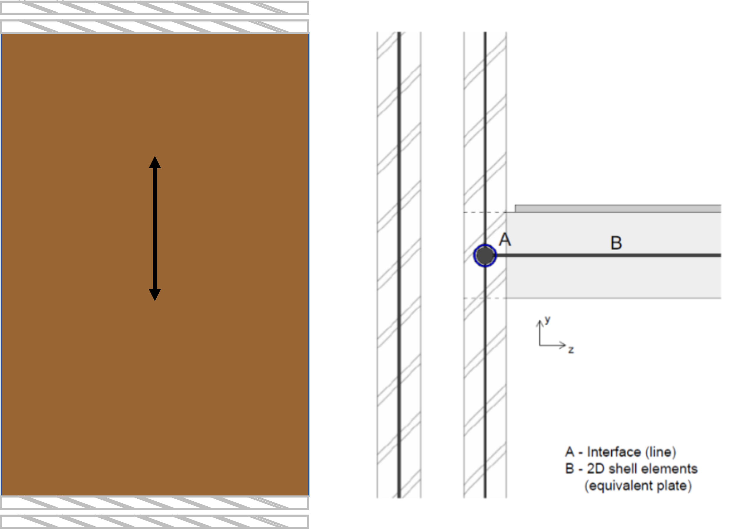
Figure 37 Connection between timber floor spanning perpendicular to wall
Timber floors spanning parallel to walls: For edges and internal walls, the timber floor should be disconnected to the masonry wall. In case the timber floor beams are implicitly modelled with the timber floor, a D2.01a interface (a no-connection interface) should be modelled between the timber floor and masonry wall. In case the floor beams are explicitly modelled, a D2.01c interface should be modelled where the timber floor and beams are disconnected to the masonry wall.
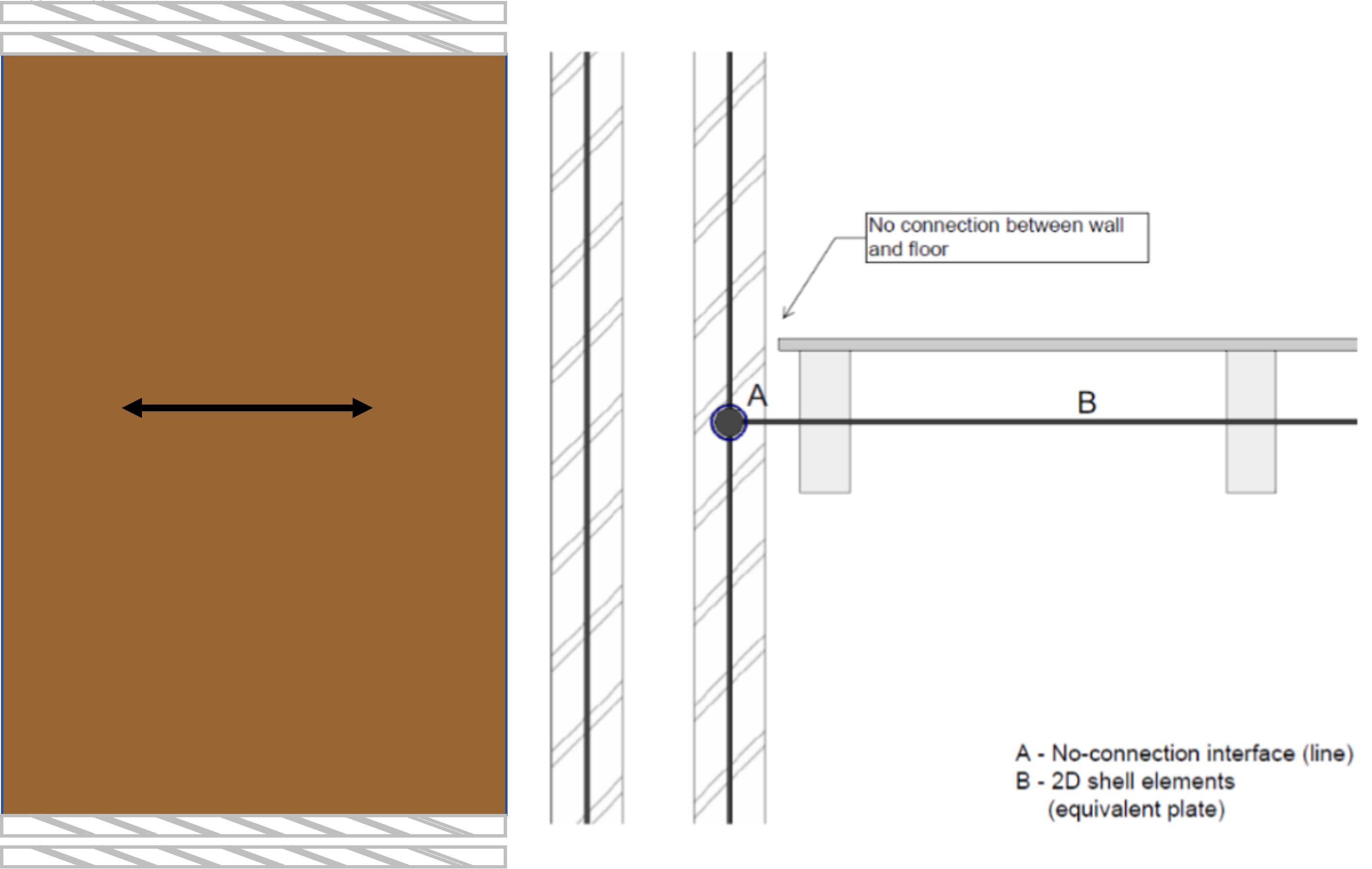
Figure 38 Connection between timber floor spanning parallel to wall
Timber roof beams and masonry walls: In case the inclined timber roof beams are connected directly to the masonry wall then there should be a hinged connection modelled between them. In case there is an explicitly modelled wall plate, the beams should be connected to the wall plate through a hinged connection and disconnected to the masonry wall. Furthermore, the masonry wall and the wall plate should be rigidly connected.
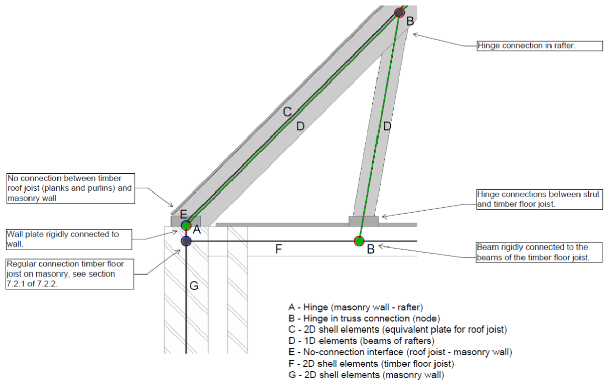
Figure 39 Connection between inclined roof beam and masonry wall
Timber/concrete/steel beam supporting the floor above: A rigid connection should be modelled between any beam present directly below a floor and supporting it.
Collar tie and roof plate: A rigid connection should be modelled between a collar tie (modelled as an equivalent truss) with the roof plate.
Note
If you deviate from the BoD, discuss it with your LE and mention it in the report.
Workflow for connections in VIIA
Figure 40 FEM-model in DIANA without connections.
Note
The structural engineer is responsible that the behaviour of the connections in the model represent the real behaviour in the building.
Step 1 - Determine the required behaviour in the FEM-model
This step involves the selection of the behaviour based on the findings in the inspection. The following items should be addressed:
Identify the locations or connections that need to be modelled.
Identify the condition of the connection (quality of connecting materials) as the presence of cracks can result in a connection loss.
Identify how the connection in the building will behave when loaded in compression, shear, tension etc.
Identify the material of the two connecting structural elements, eg. steel-wood, wood-masonry, wood-wood (timber) etc.
Identify whether the connecting elements are prefabricated or in-situ. The connection type differs per fabrication method.
Identify whether the connection is parallel or perpendicular to the spanning direction of the elements.
Identify whether the connection should be modelled with linear or non-linear material model. Usually existing connections are modelled with non-linear behaviour and new connections such as strengthening measures can be linearly modelled.
Step 2 - Select connection detail
After identifying all aspects the required connection is selected in the Basis of Design document chapter 7.
If the detail available in the Basis of Design document doesn’t sufficiently describe your connection, discuss with the lead engineer and technical master how best to model it. Keep in mind that the model should comply with the Basis of Design document. In deviating cases this means the knowledge team should check the suggested modelling method and add it to a new version of the Basis of Design document. You can deliver the engineering report, but add the connection explanation to the document (don’t wait for the release of the new version of the Basis of Design).
Step 3 - Create an overview for the Engineering Report appendix
All selected connections should be indicated on the (structural) drawings of the building. These drawings are used for communication (with lead engineer etc.) and are part of the final deliverable, TVA (in the annex).
Step 4 - Model and check the connections
The following sections provide information on how to model and check connections in DIANA and how to create them using the viiaPackage. This step requires for the engineer to make sure the selected behaviour is indeed modelled correctly in the FEM-model. There are tools available to the engineer that can assist in this process. If the connections do not exhibit the expected behaviour, necessary adjustments need to be made by the engineer.
Connections in DIANA
The following connection types are common in NLTH analysis. In this section the different connections in DIANA are described along with the way they work.
Hinge
Involves the tying of the degrees of freedom of two different shapes. Hinges in DIANA have the
option to specify the translational and/or rotational degrees of freedom to be retrained.
Boundary interface element
These are interface elements that have supports at one edge of the interface element. They are used for modelling the
support and soil-structure interaction of the shallow foundation.
No-connection
Disconnects two shapes by creating separate nodes. Used when the connection between shapes cannot transfer any force or
when no connection exists between them.
Unite
Rigidly connects two shapes that have been disconnected by an interface element present at only one of the shapes.
Interface element
An interface connection will define a special relation between shapes. The relation can be between
touching shapes (close mode) and non-touching (open mode) shapes. The shapes connected by interfaces are classified as
source or target shapes. In DIANA red represents the source shape, and blue the target shape. The interface orientation
(normal direction) should be directed from source to target geometry. Interface
elements are composed of 2 vertices/edges/planes.
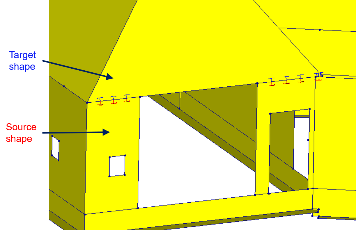
Figure 41 Example of visualisation of the source and target in DIANA.
The following interface definitions (of axes) are used in DIANA. On the right side the most common used type in the VIIA project is shown.
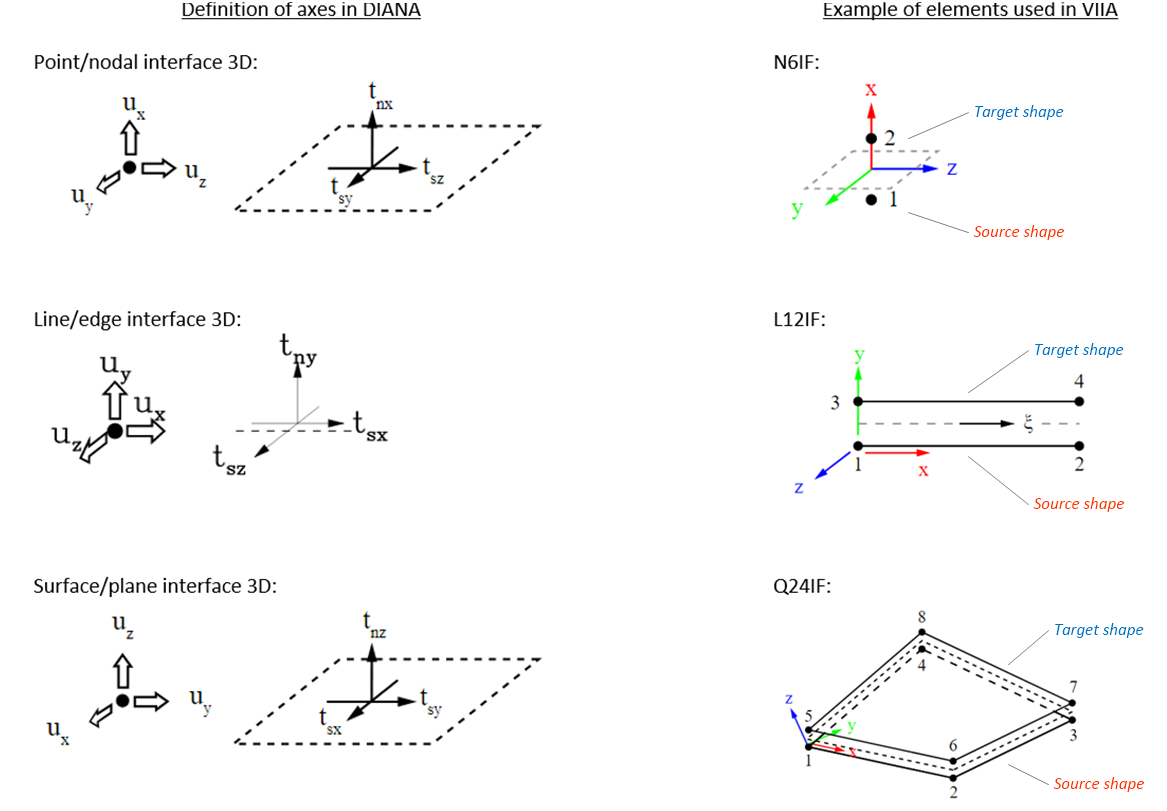
Figure 42 Interface definitions in DIANA and common elements in VIIA.
To identify source and target shapes for a specific connection/interface, the convention followed is that the load is transferred from the target to the source shape. The source shape takes up the load from the target shape and transfers it further to the other building elements. In order to correctly identify the source and target shapes, the user can refer to the viia_constants.yaml file in the viiapackage. Some common examples are:
D2.01 interface: Wall is the source shape and floor is the target shape.
D2.01b Interface: Wall is the source shape and beam is the target shape.
Roof-Wall line hinge: Wall is the source shape and roof is the target shape.
Material model
The material model is defined based on the local axes directions, thus it is important to know the normal and tangential/shear traction stress directions for each interface elements. The material model can be linear or non-linear.
Interface element geometry
The interface element geometry describes the thickness or area of the interface, as well as the local axes. In almost all cases, these geometry details are determined automatically based on the connection detail and the orientation of the source and target shapes.
Checking the local axes
The direction of the local axes must always be verified in DIANA. Make sure that the local axes represent reality such that the normal axis points in the direction of tension, and the tangential axes point in the directions of shearing.
Note
Due to how DIANA generates the local axes of interfaces and how they are corrected in the viiaPackage, the local axes must be checked only after creating the model and generating the mesh using viia_create_model() and viia_create_datfile().
Run a linear static analysis and check if compressive/tensile stresses are as you expect. Compressive stress is negative and tensile stress is positive in DIANA, irrespective of the orientation of the local axis.
The figure below shows an example of the local axes of interfaces between walls and roofs. In these cases, the walls are the source shapes, and the roofs are the target shapes. The y-axis is the normal axis, and thus points up towards the roof from the wall.
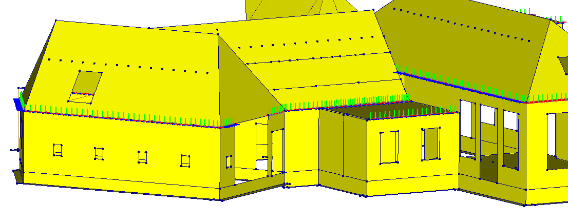
Figure 43 Checking local axes in DIANA.
Interface modes
This section explains the different interface modes that can be applied and which considerations to take into account when applying them, and in the section Connections in viiaPackage, it is explained how to actually apply them in the viiaPackage.
Close interfaces
For close interfaces, both the source and target faces/edges/vertices must be specified. When applying a ‘close’
interface and more than two shapes are coincident, the rest of the shapes will be automatically disconnected. This
means that all the connections must be defined by the engineer. You can use the ‘Unite’ or ‘Rigid’ connections to
connect the shapes rigidly again. Use a ‘close’ interface only when the shapes of interest are geometrically
coincident. In case they are not, use an ‘open’ interface. Be sure that the shapes are connected and share the same
faces/edges/vertices. A fast check is to generate the mesh before adding the connections and check if only one node is
created between the connection of the shapes.
Figure 44 Close mode interfaces in DIANA.
As shown in the figure the ‘close’ interface is created between the two selected shapes. All other shapes are disconnected and should be united again.
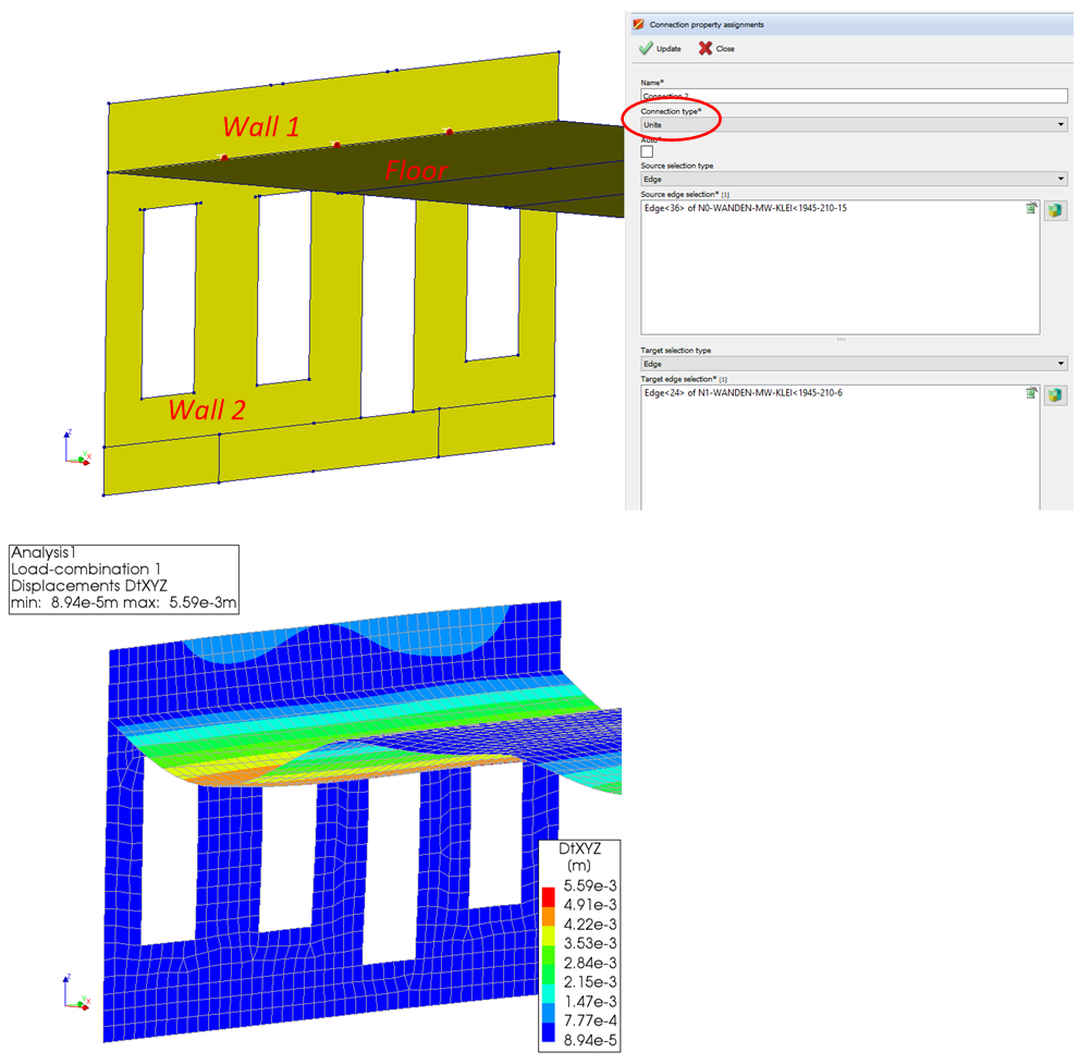
Figure 45 Close mode interfaces in DIANA.
More information on the close interfaces can be found here: ‘Further reading on close interfaces in DIANA’.
Auto interfaces
For auto interfaces, only the source faces/edges/vertices must be specified. The coincident target
faces/edges/vertices are found automatically. Modelling interfaces with auto interface mode is faster in the process
because there is no need to specify target information. If more than two shapes are coincident, the rest of the
shapes will remain rigidly connected. Be sure that the shapes are connected and share the same faces/edges/vertices,
and it’s not recommended to create more than one auto interface at one location because the source shapes might be
selected in the wrong way, which results in an incorrect connection. A fast check is to generate the mesh before adding
the connections and check if only one node is created between the connection of the shapes.
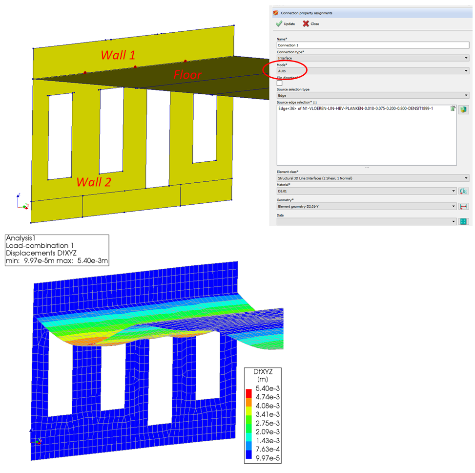
Figure 46 Auto mode interfaces in DIANA.
Open interfaces
For open interfaces, the source and target faces/edges/vertices and the source and target anchors are required. Use an
‘open’ interface when the shapes of interest are not geometrically coincident. In case they are, use a ‘close’
interface.
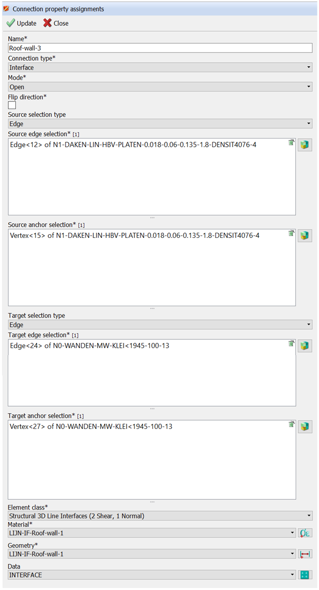
Figure 47 How to create an open interface in DIANA.
Check the creation of the interfaces and beware of crossing elements.
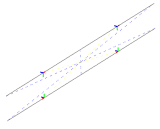
Figure 48 Check the created open interface elements in DIANA, example of incorrect assignment of source and target anchors.
Connections in viiaPackage
There are several functions available in the viiaPackage that can help you inspect the various shapes and their connectivity, and subsequently add a connection between them. Some of these functions will be explored in this section. The script assumes that when applying the connections, the model is properly connected. Before applying connections you need to connect all your shapes properly. This means that when two shapes are connecting they share the same line shape geometry in the PY-memory.
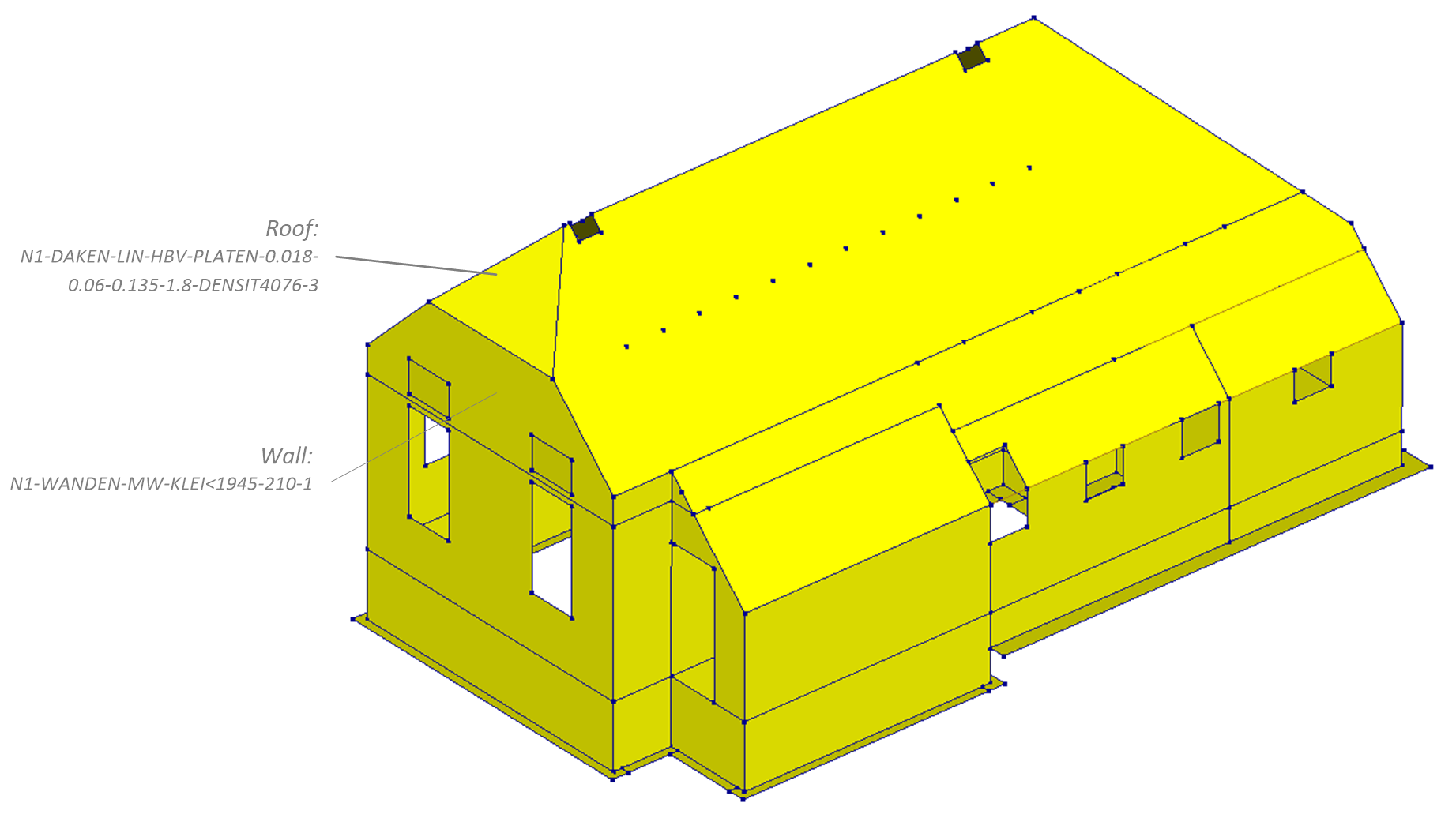
Figure 49 Shapes to be connected in this example.
To make sure the shapes are connected use the _viia_connect_all_shapes() function.
project.viia_connect_all_shapes()
You can check whether certain shapes are connected with the method
get_connecting_shapes(). Remember to retrieve an object with
viia_get().
roof = project.viia_get(name='N1-DAKEN-LIN-HBV-PLATEN-0.018-0.06-0.135-1.8-DENSIT4076-3')
roof.get_connecting_shapes()

>>> [RHDHV-Shape: N1-WANDEN-MW-KLEI<1945-210-1,
     RHDHV-Shape: N1-DAKEN-LIN-HBV-PLATEN-0.018-0.06-0.135-1.8-DENSIT4076-1-1,
     RHDHV-Shape: N1-DAKEN-LIN-HBV-PLATEN-0.018-0.06-0.135-1.8-DENSIT4076-2-1]
Connecting means the two shapes share one or multiple shape-geometries (node, line, polyline, etc.). To get any shared
line you can use the method get_connecting_lines().
roof = project.viia_get(name='N1-DAKEN-LIN-HBV-PLATEN-0.018-0.06-0.135-1.8-DENSIT4076-3')
wall = project.viia_get(name='N1-WANDEN-MW-KLEI<1945-210-1')
roof.get_connecting_lines(wall)

>>> [RHDHV-Line: L0277 [[5.83, 0.0, 4.88], [3.03, 0.0, 4.88]]]
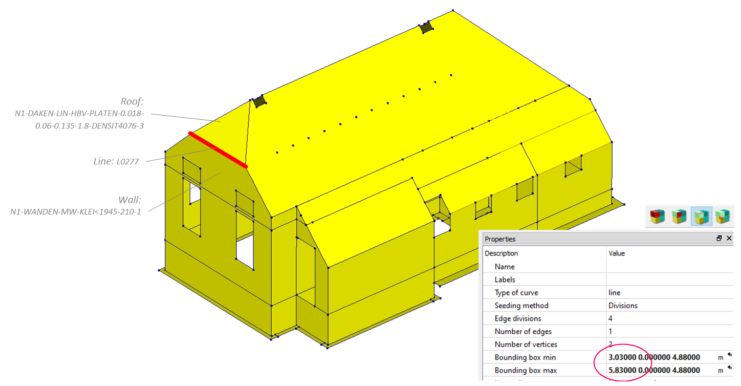
Figure 50 Shared shape geometry (line), checking in DIANA.
It could be that there are multiple connecting lines.
floor = project.viia_get(name='N1-VLOEREN-LIN-HBV-PLANKEN-0.022-0.060-0.120-0.600-3')
roof = project.viia_get(name='N1-DAKEN-LIN-HBV-PLATEN-0.018-0.06-0.135-1.8-DENSIT4076-1-2')
roof.get_connecting_lines(floor)

>>>> [RHDHV-Line: L0786 [[8.005, 8.88, 2.705], [8.005, 10.36, 2.705]],
     RHDHV-Line: L0787 [[8.005, 10.36, 2.705], [8.005, 13.66, 2.705]]]
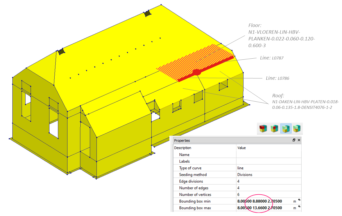
Figure 51 Multiple shared shape geometries (2 lines), checking in DIANA.
The example underneath creates detail 2.01 from the basis of design document.
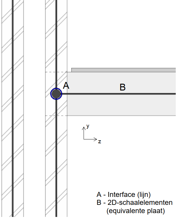
Figure 52 Detail 2.01 in the Basis of Design document.
The next step is to create the interface with the function
viia_create_connection(). Note that in VIIA, close interfaces are mostly used.
project.viia_create_connection(
    source_name='N1-WANDEN-MW-KLEI<1945-210-1',
    target_name='N1-DAKEN-LIN-HBV-PLATEN-0.018-0.06-0.135-1.8-DENSIT4076-3',
    detail='D2.01',
    is_linear=False)
Using automatic interfaces and hinges in viiaPackage
To further simplify the application of connections it is possible to use automatic application of interfaces in
viiaPackage using function viia_auto_interfaces() and
viia_auto_hinges(). Like
viia_create_connection() the script assumes that when applying the connections,
the model is properly connected. Before applying automatic connections and hinges you need to connect all your shapes
properly. This means that when two shapes are connecting they share the same line and/or point shape geometry in the
python-memory.
Note
The functions are not meant to produce final interfaces for an object! There are made merely to provide a quick and standard way to bulk create simple interfaces so an engineer can focus his/her effort to special and complex connections.
Usage of automatic interfaces
The algorithms differ between viia_auto_interfaces() and
viia_auto_hinges(). The function
viia_create_connection() works by creating a dictionary of connection
‘fingerprints’ based on connection library specified in viiaPackage. During runtime each pair of connecting shapes is
examined and compared against this library so interfaces can be applied. The function uses the functionality of
viia_create_connection() to apply the interfaces in the PY-memory. It will also
select prescribed source and target relationship.
The generation of connection ‘fingerprints’ are based on 4 key properties of the shapes. Namely: material, structural type, the direction of the strong axis and spacial orientation. An example of how the fingerprint is assembled can be seen in a figure below:
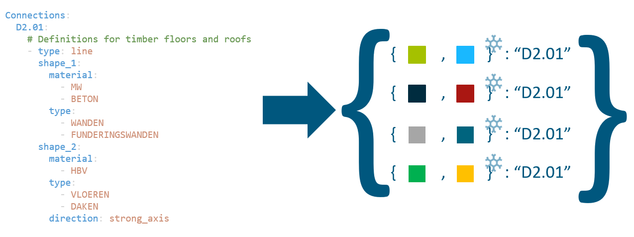
Figure 53 Schematisation of how fingerprints are generated from the connection library.
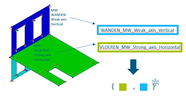
Figure 54 Schematisation of how fingerprints are generated from the connecting shapes during runtime.
However, to correctly define interfaces additional considerations are needed.
From the example depicted above the floor will form the same fingerprint with the wall above and the wall below it.
Therefore, an additional algorithm is considered that will neglect interfaces that form an incorrect load path.
Furthermore, because of the use of close interfaces, other shapes at the connection are automatically disconnected
in DIANA. To prevent this, shapes at the connection that do not have an interface assigned will be united. Point
unites are also created at the ends of the connecting line segments to prevent disconnected end nodes with the
adjacent shapes. This functionality works when using both
viia_auto_interfaces() and
viia_create_interface().
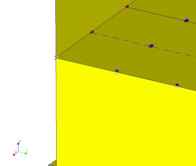
Figure 55 Adjacent faces united at a point due to an interface between the floor and the wall
Note
Although, uniting shapes are done automatically, please pay attention if you do not have double nodes between shapes that should be connected.
Additionally to determining load path, one extra consideration is implemented. That is line mass connections. Line masses are used to add dead load from the removed nonstructural elements back to the model, These masses can be applied on walls, roofs, floors, beams, etc. Typically one would expect that the masses are only connected to a “host” shape and they do not interfere with other connections. Because of this, a connection hierarchy is implemented. Line masses will be united only with a shape that is above in hierarchy and they will be disconnected with the rest.
Hierarchy of the line mass host shapes are as follows:
FUNDERINGSWANDEN
WANDEN
VLOEREN
BALKEN
DAKEN
In order to use viia_auto_interfaces() simply call the following code
in your mainscript:
project.viia_auto_interfaces()
Usage of automatic hinges
The function viia_auto_hinges() follows a bit different algorithm
than viia_auto_interfaces(). Mostly due to the fact most of the beams
when connecting to another beam should form a hinged connection. Specifying all of these combinations in the connections
library would be counterproductive. Therefore, a different algorithm for hinged connections is set up.
The algorithm explodes each node that is associated with beams or columns then between all beam pairs at the nodes hinges are created. Unless two beams in the pair are parallel, in that case, beams are united. If a beam in the pair is connecting to a surface a hinge is also created unless the pair already has an existing interface between them. If two surfaces are connecting a line unite is created (currently no support for point unite when more than one node is connecting) unless that pair has already an interface defined.
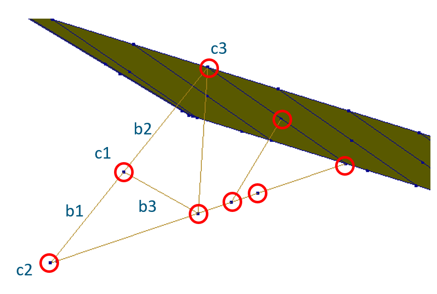
Figure 56 Example of beam configuration
Let’s consider the above example. There a truss is depicted that is connected to a roof plate. At connection c1 the algorithm would apply point unite between beams b1 and b2 as they are parallel to each other, then it will create a hinge between beam b3 and one of the united beams. At connection c2, one hinge will be created between two connecting beams. At connection c3 one master node will be selected and if no prior interfaces are created a hinge will be made between all the beams and the plate.
Note
Even though the algorithm ignores prior connections please do not create auto hinge before executing this function. DIANA auto hinges do not have source and they only have a target, therefore they prevent any kind of additional hinge from being created at the connection.
Note
When using the function viia_auto_hinges() it is advised to use
torsional stiffness element data for beams and columns to prevent rotations around their axes.
In order to use viia_auto_interfaces() simply call the following code
in your mainscript preferably after creating interfaces:
project.viia_auto_hinges()
Overriding automatic decisions
Automatic interfaces and hinges are a great choice to blanket apply connections in an object. However, models of the objects often do not have sufficient information to create all the connections automatically. In that case, manual intervention is needed by the engineer. Automatic connections and hinges provide various facilities to control where and what connections are created.
Note
Be careful with the interfaces at the locations where many shapes connect (beams, walls, floors, line mass, etc.) currently in some cases such locations cannot be solved automatically. Manual intervention is required!
For the function viia_auto_interfaces() several types of overrides
can be specified:
override_connections - Replacing automatic decision with a custom one for a pair of shapes. If an interface is created that is not suitable, an argument can be passed to the function to create another interface instead. Pay attention to the fact that the order of shapes specified follows the input rules of
viia_create_connection(). Let’s imagine a scenario where two shapes connect in the model. Namely a floor (‘N1-VLOEREN-LIN-HBV-PLANKEN-0.022-0.05-0.15-0.65-0’) and a wall (‘N0-WANDEN-MW-KLEI<1945-100-2’) by default a D2.01 interface will be generated between these two shapes. However, an engineer sees in the inspection that these two elements are indeed disconnected. In this case, an override can be specified to apply NOCON-L. Note that a similar effect can be achieved by creating the interface between the shapes manually prior execution of the function. As all existing interfaces are taken into account as overrides.project.viia_auto_interfaces(override_connections=[['N0-WANDEN-MW-KLEI<1945-100-2', 'N1-VLOEREN-LIN-HBV-PLANKEN-0.022-0.05-0.15-0.65-0','NOCON-L']] )
It is also possible when giving an override to also specify keyword arguments to be used for the creation of the interface:
project.viia_auto_interfaces(override_connections=[['N0-WANDEN-MW-KLEI<1945-100-2',
    'N1-VLOEREN-LIN-HBV-PLANKEN-0.022-0.05-0.15-0.65-0','D2.01', {"is_linear": True}]] )
Note
When the analysis type is SBS all nonlinear connections are automatically transformed to linear. You will be notified about this transformation if you did not explicitly set all your connections to linear.
disable_connections - Now imagine a scenario where an engineer wants at that location to create a manual interface in DIANA as no interfaces in the library suits his/her needs. In that case, any automatic assignments at the location should be disabled. This can be done in the following way:
project.viia_auto_interfaces(disable_connections=[['N0-WANDEN-MW-KLEI<1945-100-2',
    'N1-VLOEREN-LIN-HBV-PLANKEN-0.022-0.05-0.15-0.65-0']] )
disable_interfaces - UPR states that timber beam has to be connected to a timber floor with D2.07 interface. However, sometimes the connection is very strong and rigid behaviour could be prefered. In that case, an interface type can be disabled throughout the model:
project.viia_auto_interfaces(disable_interfaces=[['D2.07']] )
replace_interfaces - sometimes it may be needed that interfaces should be substituted with an alternative. This can be achieved by (Substitute “D2.07” with “D2.01”):
project.viia_auto_interfaces(replace_interfaces={'D2.07':'D2.01'} )
It is also possible to replace interface to the same one but specify keyword arguments for creation of these interfaces:
project.viia_auto_interfaces(replace_interfaces={'D2.01':['D2.01',{'is_linear':True}]} )
For the function viia_auto_hinges() several types of overrides can be
specified:
override_hinges - By default all rotational degrees of freedom are free when using the function, however, an override can be specified to apply different constraints. Override is expressed in notation ‘H_RRF’ where H stands for Hinge, R stands for rotate and F stands for fixed. So, in case a hinge is needed with x,y rotations free and the only z constrained:
project.viia_auto_hinges(override_hinges=[['N2-BALKEN-STAAL-S235-HEA140-5','N2-BALKEN-STAAL-S235-SHS80x6-1',
   'H_RRF']] )
disable_nodes - In certain situations a fixed connection between beams is needed in a presence of stiffeners. A rigid connection for all members at the node can be achieved by disabling automatic hinges for a particular node:
project.viia_auto_hinges(disable_nodes=[project.find_node(point=[0.1, 0.5, 2.7])] )
disable_hinges - In certain situations a rigid connection between specific members at a node is needed, while retaining hinges on other members at the node. A rigid connection between specific members at a node can be achieved by disabling automatic hinges for a particular pair of shapes:
project.viia_auto_hinges(disable_hinges=[['N2-BALKEN-STAAL-S235-HEA140-5','N2-BALKEN-STAAL-S235-SHS80x6-1']] )
Note
If you see that automatic connections and hinges generate too many connections and you want more exceptions to better control that. Please file your suggestion as a bug report so the functions can be improved for everyone!
Check connections
There are tools available in the viiapackage that can assist the user in verifying the connections present in the FEM model. In case the connections are modelled incorrectly, the user should redefine the connections so that they exhibit the expected behaviour.
Checks to be performed
Connections are checked using the viia_check_mesh() function. In this function, three
checks are inherently performed as described below:
Check for master-slave relations: For all the hinges in the FEM model, there are 2 rules that need to be followed. Firstly, the master mesh node(s) in a specific hinge should not be a slave mesh node in another hinge. Secondly, no support should be modelled on a slave mesh node. If any of these rules is violated, a warning is logged in the mesh mesh check report specifying the connection name and mesh node ids where the corrections need to be implemented.
Check for no-connections: For all the no-connections present in the FEM model, the source and target shapes should not share common mesh nodes at the location of the no-connection. If this is not the case, a warning is logged in the mesh check report specifying the connection name and the common mesh node ids.
Check for unites: For all the unite connections present in the FEM model, the source and target shapes should have the same mesh nodes at the location of the unite connection. If this is not the case, a warning is logged in the mesh check report specifying the connection name and the mesh node ids that are different for the source and target shapes.
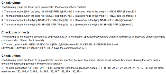
Figure 57 Example of warnings generated in the mesh check report
In addition to checking the warnings present in the mesh check report, the user should also check the warnings printed in the log file about the connections which were unable to be created in the mesh. The user should ascertain that all the connections in the FEM model are complying with all the above mentioned checks. If any of the checks is not passing, the user should make adjustments in the detailing of the connections so that the checks are compliant. In case the checks are passing, a message is displayed in the mesh check report to notify the user that the connections are modelled correctly.
Connection data at a node
An overview of mesh nodes and connections at a particular node can be generated by using the
viia_node_data_diana() function. This function can be called after the connections
have been defined and the dat-file has been created.
project.viia_node_data_diana(view_nodes=[[0.1, 0.5, 2.7]])
This function works in the DIANA command prompt environment, and it will return the DIANA mesh node ids and the connection and tying information at the location of the specified node in the form of a pdf file. An example of the pdf generated by this function is shown below.
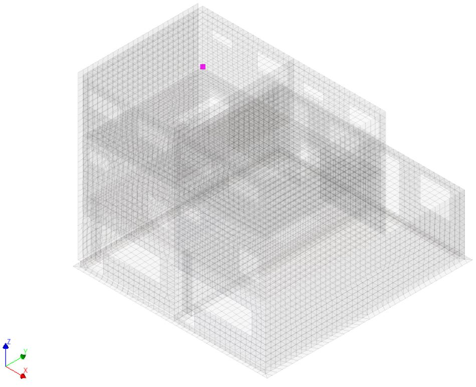
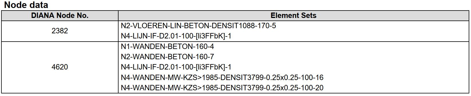
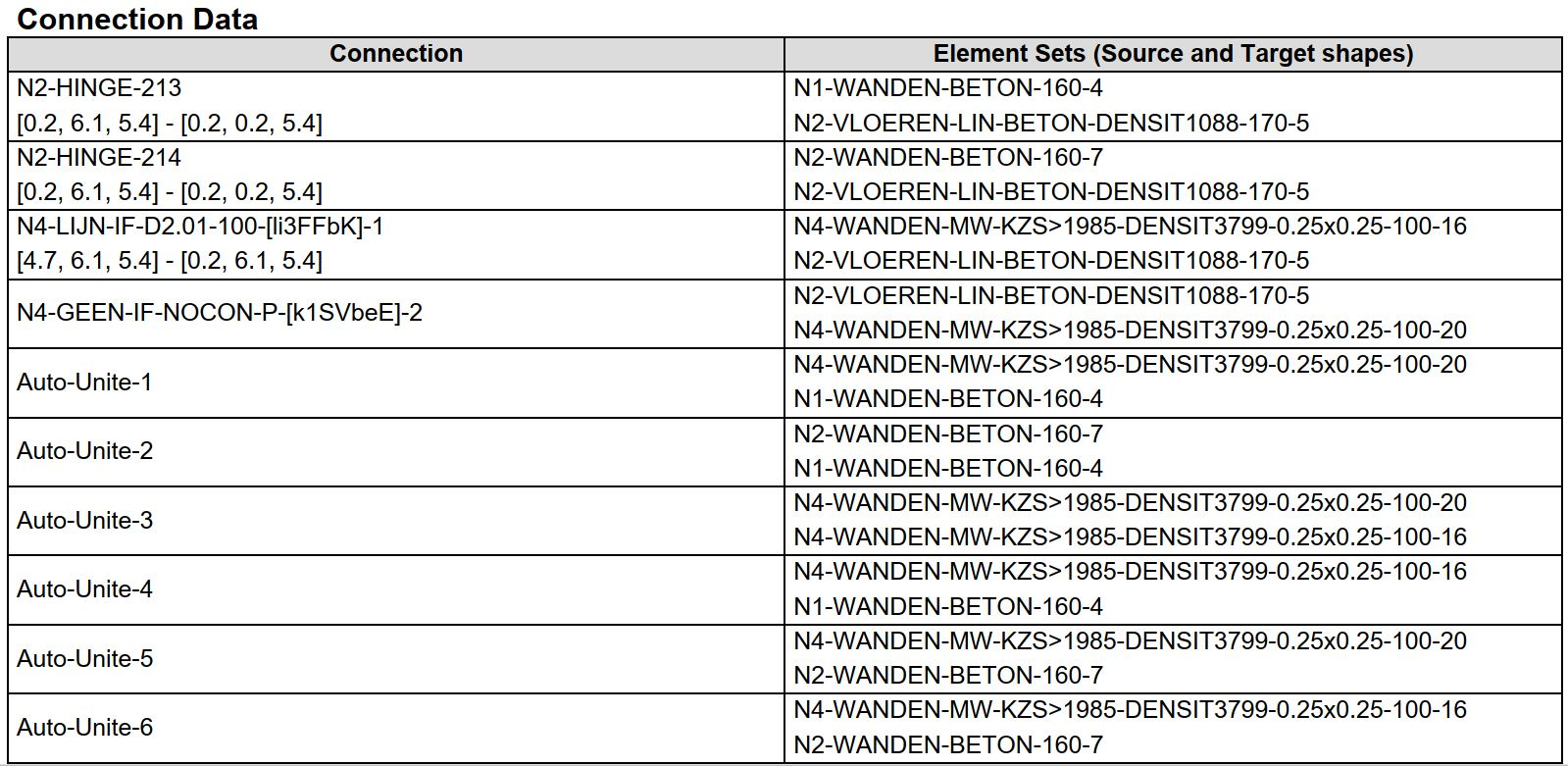
Figure 58 Example of node data pdf document
The function creates an image showing the location of node in the model and two tables: Node data and Connection data.
Node data table: This table shows the data of all the mesh nodes at the same coordinate as that of the specified node selected in the model. In the left column, the DIANA node ids are specified and in the right column, shape names containing the corresponding mesh node. This can be useful in determining how two different shapes are connected. For example, if two shapes are rigidly connected, then there should be a fixed connection at their interface and both the elements should share a common mesh node. On the other hand, if there is a hinge between two shapes, then two separate mesh nodes should be present at the interface, belonging to each of the shapes. The user can use this node data summary to verify the connection of elements at specific node locations.
Connection data table: This table gives the data of all the connections present at the specified node selected in the model. In the left column, the name of the connections is specified and in the right column, the source (top) and the target (bottom) shapes corresponding to a particular connection are specified. Sometimes there can be coordinates present in the connection name which signifies that the node is part of a line geometry, and the coordinates represent the line over which that specific connection is present. This can be used to get an overview of all the connections that are present at the node.
Connection data of a shape
An overview of connected shapes and connections at a particular shape can be generated by using the
viia_shape_data_diana() function. This function can be called after the
connections have been defined and the dat-file has been created.
project.viia_shape_data_diana(view_shapes=['N1-VLOEREN-LIN-HBV-PLATEN-0.018-0.065-0.165-0.61-1'])
This function works in the DIANA command prompt environment, and it will return the connected shapes and the connection information at the location of the specified shape. An example of the pdf generated by this function is shown below.
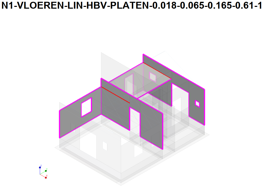
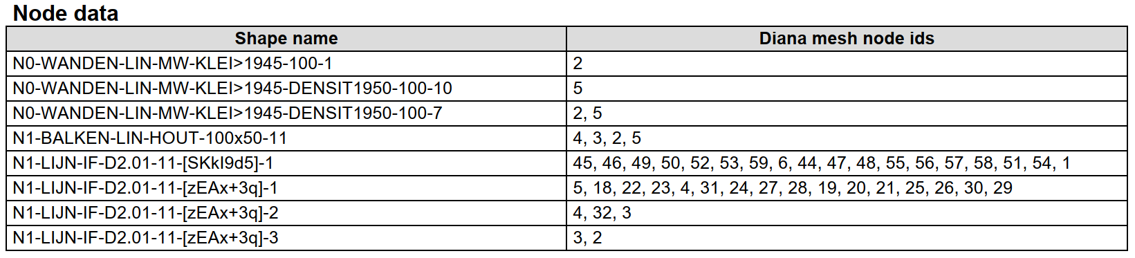
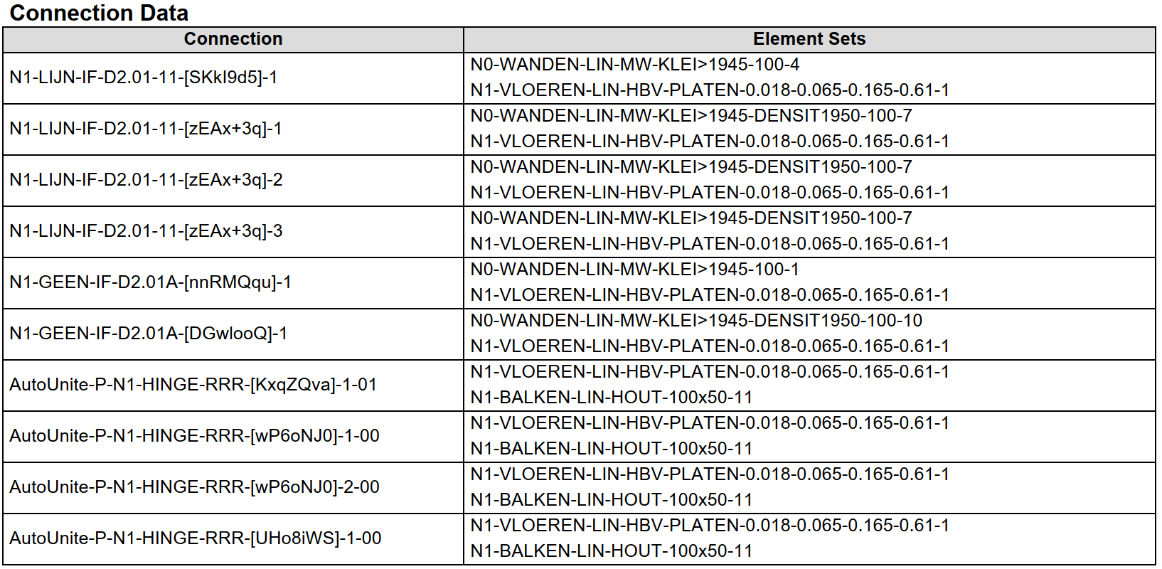
Figure 59 Example of shape data pdf document
The function creates an image showing the location of node in the model and two tables: Node data and Connection data.
Node data table: In the left column, shape names are specified that share common mesh nodes with the specified shape and in the right column, the common mesh node ids. This can be used to ascertain the connection between two shapes.
Connection data table: In the left column, the name of the connections is mentioned for which the selected shape is a part of and in the right column, the source and target shapes corresponding to that particular connection are specified.
Additional information
Further readings: LINK
Repair hinge connections
Hinges can be applied in complex configurations. In some cases the hinge cannot be meshed. This sections shows what can happen and how to fix it.
Situation
We will consider the situation that is depicted below. With on the left the ‘real’ situation and on the right the situation as modelled.
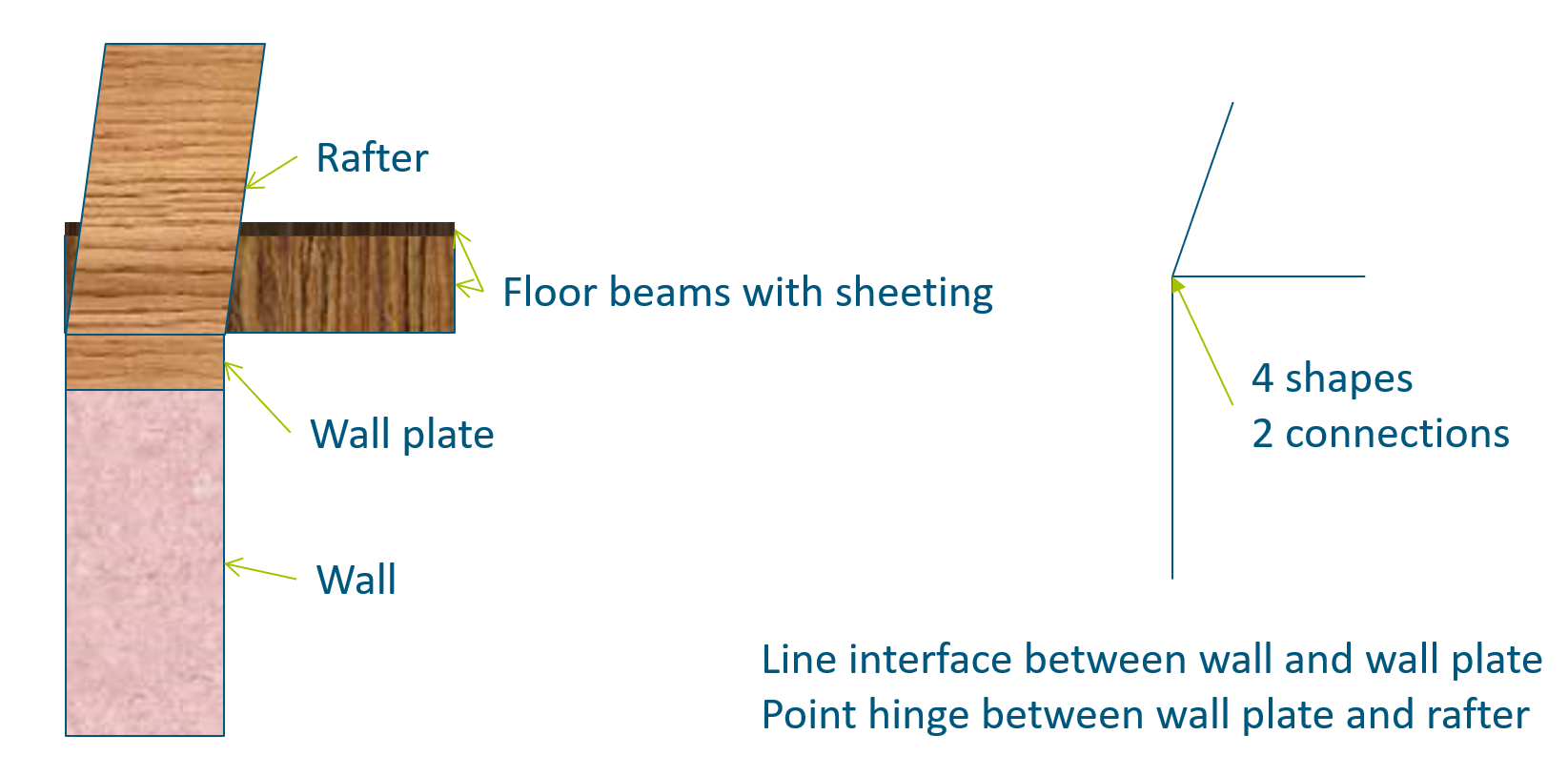
Figure 60 Connection details
In the modelled situation at one point the rafter, wall plate, floor, wall, line interface between wall and wall plate and point hinge between wall plate and rafter come together. This results in a lot of dependencies.
Problem
When the model is meshed, the point hinge didn’t appear in the mesh. While reading the dat-file from diana a warning will be raised, both in the log file and the diana message window.

Figure 61 Example of waring message
If we use the available tools to show the connection data at a node and the connection data of a shape we see what happened. AutoUnites have been made between the rafter and the floor, and between the wall plate and the floor. So the rafter is united, via the floor, to the wall plate. When the rafter and wall plate are united no hinge connection can be made between them.
Solution
When the AutoUnites are made, it will check if there are any other connections at the same point and shape. Being a bit more specific about what should be connected and what not will solve the problem. When NOCON’s between the rafter and the other shapes are present no AutoUnites will be created. The next piece of code will add the needed NOCON-P’s that are needed.
node = project.find_node([14.5, 0, 2.2])
rafter = project.viia_get(name='N2-BALKEN-LIN-HOUT-D100-7', collection='beams')
for shape in node.get_shapes():
    if shape != rafter:
        project.viia_create_connection(source=shape, target=rafter, detail='NOCON-P')