How to perform SLaMA for two-storey buildings
This guide contains the procedures for the assessment of two-storey buildings using Simple Lateral Mechanism Analysis (SLaMA).
If you have any questions while performing these procedures, please contact the Automation team.
Introduction
SLaMA for two-storey buildings as opposed to one-storey buildings is not all that different. Each wall is checked separately, and the capacity of each storey is checked based on the pier capacities. Then, it is determined which storey is the critical one, and the effective seismic mass of the system is then calculated based on the storey that is critical. The wall capacity is calculated using the critical storey and with the effective seismic mass.
So all in all, there are many steps that are the same for one and two storeys. However, there are some aspects that are more important for two storeys. Besides what’s mentioned above, a couple of differences are:
It’s more important to distribute gravity and perpendicular loads more accurately. This is because it’s important to correctly determine which storey is the critical one. If the wrong storey is determined critical, the wall capacity may be greatly overestimated or underestimated.
The areas of the walls that contribute to the seismic mass of each storey is different. This is also the case for the areas that contribute to the perpendicular load.
Required input
In the current version of the two-storey SLaMA tool, there are two input files required:
- XXXX_load_input.xlsx: This excel file contains several sheets:
input_project:
Currently not in useinput_storey: This sheet is imported into pycharm. It contains various storey-wise input of each wall such as the seismic mass from the wall, perpendicular loads from the other walls, and more.
input_storey_super: This sheet is import into pycharm. It contains input for a super storey, which is currently not implemented.
Leave this empty for now.input_component: This sheet is imported into pycharm. It contains the information about all piers and spandrels for each storey for each wall. This is information regarding their geometry and loads acting on them.
input_component_super: This sheet is imported into pycharm. It contains the information about the super piers spandrels, which is currently not implemented.
Leave this empty for now.input_diaphragm: This sheet is imported into pycharm. It contains the information about all diaphragms, such as how they are supported and which walls or diaphragms act on them.
input_connection: This sheet is imported into pycharm. It contains information about all the connections in the building that must be analysed.
input_connection_manual: This sheet is imported into pycharm. No calculations are made with this input, it is only used to display these connections in the readout.
Perpendicular loads: This sheet is not imported into pycharm, but it is used to calculate the input in input_storey.
Data validation: DO NOT CHANGE. Simply contains lists for data validation used in the other sheets.
slamaParameters.py: This file contains various global variables, some of which have to be defined for each new object. This is information such as seismic intensity, floor and roof live and dead loads, and more.
An example of the excel file can be found on gitlab.
The slamaParameters.py file is in the two-storey SLaMA tool and must be edited directly.
Wall geometry and loads
Step 1 - Wall and pier division
For two-storey buildings, the walls are divided in the same way as with one-storey buildings.
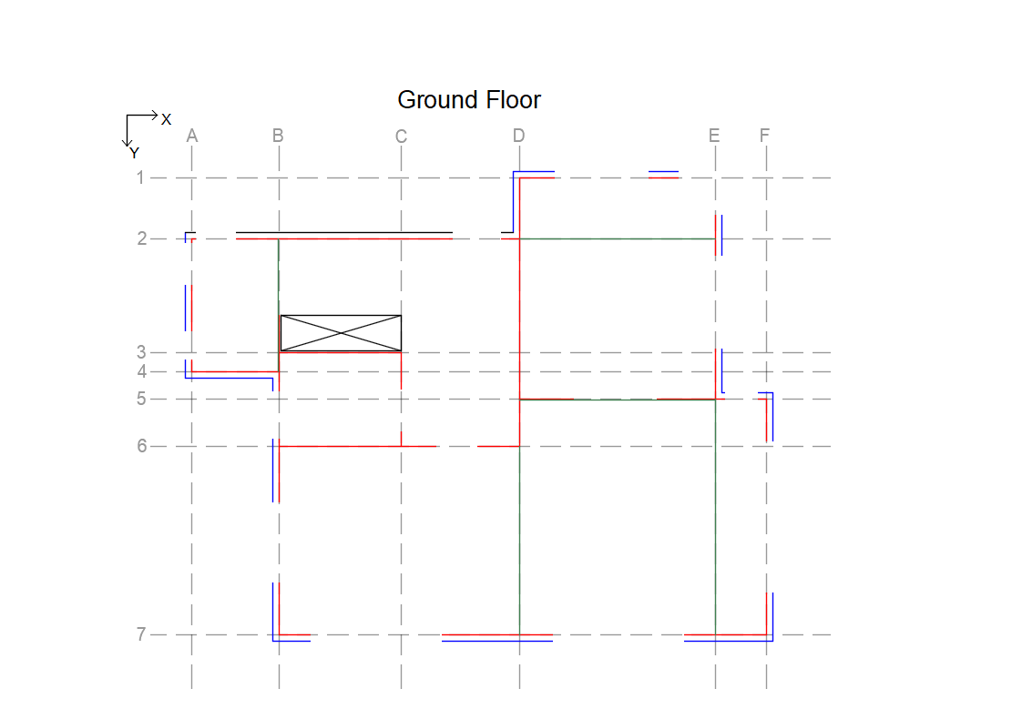
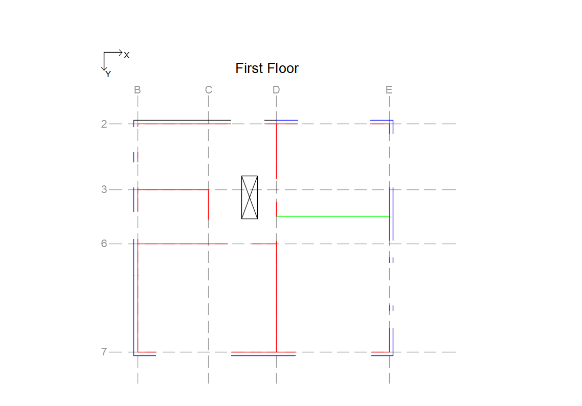
Figure - Example of wall division of ground and first floors. The grid lines indicate the wall names.
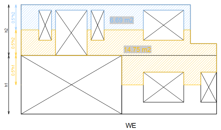
The piers, spandrels and nodes are also determined in a very similar manner. However, as seen in the image below, the spandrels and nodes extend further up if the wall continues past the 1st floor. The parts of the walls that are not considered piers, spandrels, or nodes, are those in blue in the example, below. They only contribute as a gravity load.
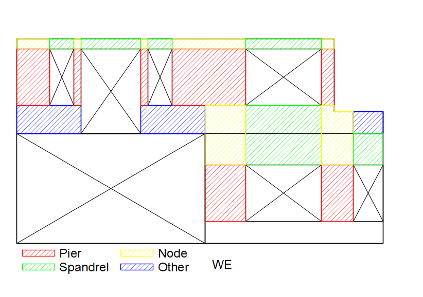
Figure - Example of pier, spandrel, and node division of wall WE.
Step 2 - General input for piers, spandrels and stories
Input sheet: ‘input_component’
Each row contains information for one component, which can be either a pier or a spandrel.
Input: ‘wall’
Wall that the component belongs to.Input: ‘storey’
Storey that the component belongs to.Input: ‘component’, ‘component_id
Type of component (pier or spandrel), and its number in the storey with 1 starting on the left.Input: ‘material’
Material of the component.Input: ‘length’, ‘height’, ‘thickness’
Dimensions of the component.
Input sheet: ‘input_storey’
Input: ‘wall’
Wall that the storey belongs to.Input: ‘storey’
Number of the storey.Input: ‘super’
Not supported. Leave as False.Input: ‘NSCE’
True if wall is an NSCE. See description of oop_type for more information.Input: ‘material’
Material of the storey.Input: ‘length’, ‘height’, ‘thickness’
Dimensions of the storey.Varying thickness not supported yetInput: ‘rigid_floor’
True if there is a rigid floor on top of the wall to set the boundary condition as fixed.Input: ‘area_wall_bottom’
The area below the piers for ground floor storeys. Necessary for the load on the foundation
Step 3 - Load distribution: Gravity loads
In the one-storey method, the loads are assumed distributed uniformly at the top of the storey wall. With two storeys, it is more important to distribute the load to the correct piers in order to accurately assess the critical storey and its capacity. The sections below show how the gravity loads are distributed to the different piers.
Walls
Input sheet: ‘input_component’
Input name: ‘wall_area_above’
The gravity loads on the piers are simply defined by the area of the wall above that acts on each pier. The first figure shows the area of wall WE that acts on the piers on the ground floor. The area on the left goes to a pier in that’s part of wall W7 because the load is transferred through a steel beam to W7. The two other areas are distributed to the two piers on the ground floor of wall WE.
The second figure below shows the area of wall WE that acts on the five piers on the first floor. Now all the areas are distributed to piers in wall WE.
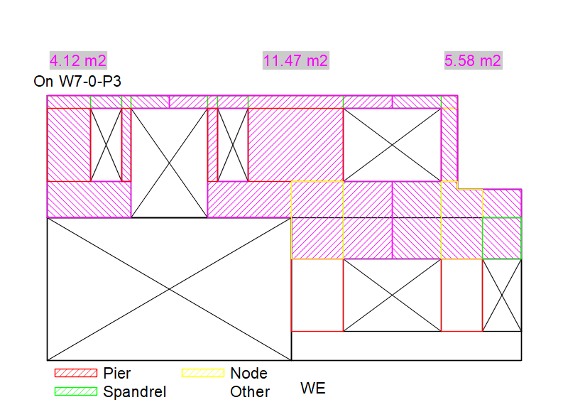
Figure 233 Wall areas acting as gravity loads on the ground storey piers
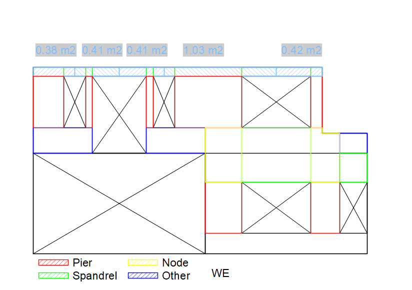
Figure 234 Wall areas acting as gravity loads on the first storey piers
Floors
Input sheet: ‘input_component’
Input name: ‘floor_area_self’ and ‘floor_area_above’
The gravity loads on the piers from the floors are determined based on the tributary area according to the spanning direction of the floors. The first figure below shows which first floor areas acting on the various ground storey piers, and the second figure shows the attic floor areas acting on the first storey piers. All the floors, except the balcony floors, span in the y-direction.
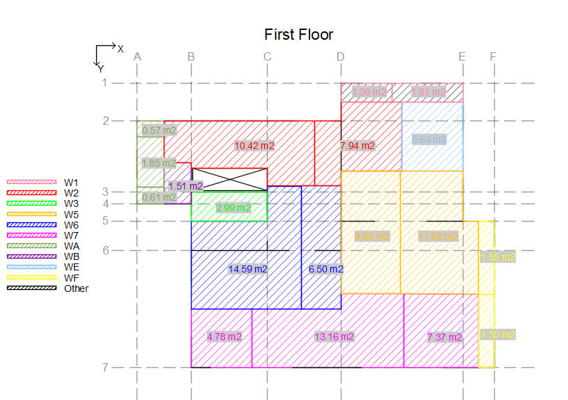
Figure 235 First floor areas acting as gravity loads on the ground storey piers
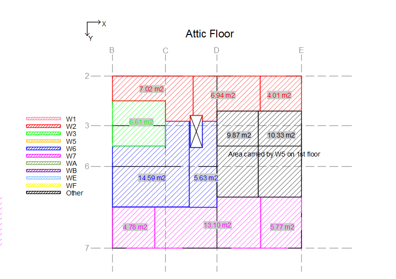
Figure 236 Attic floor areas acting as gravity loads on the first storey piers
Roofs
Input sheet: ‘input_component’
Input name: ‘roof_area’
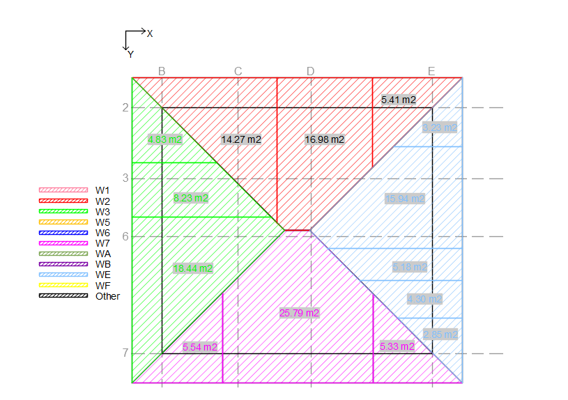
Figure - Roof area acting as gravity loads on the first storey piers
Load on spandrels
Input sheet: ‘input_component’
Input name: ‘wall_area_above’, ‘floor_area_self’, ‘floor_area_above’, and ‘roof_area’
It’s important to also consider the load acting on the spandrels in order to determine whether they are weak or strong. The figures below show how the loads from the walls, floors and roof act on the spandrels.
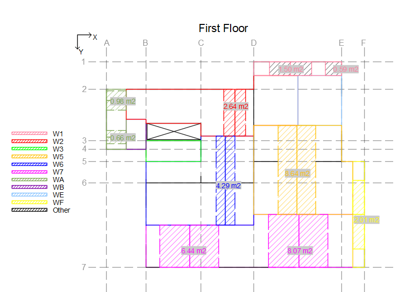
Figure 237 First floor areas acting as gravity loads on the ground storey spandrels
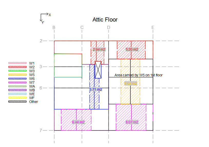
Figure 238 Attic floor areas acting as gravity loads on the first storey spandrels
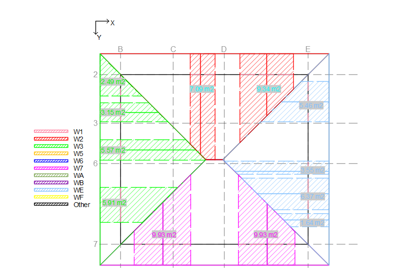
Figure 239 Roof area acting as gravity loads on the first storey spandrels
Step 4 - Load distribution: Seismic loads
The effect of gravity and seismic loads in the building are considered differently when assessing the seismic capacity.
Walls
Input sheet: ‘input_storey’
Input name: ‘wall_area_seismic’
The seismic weights of the walls acting on each storey are determined based on the heights of the stories. When considering the capacity of a specific storey, the height of the part considered to act on that storey is halfway down to the floor below, and halfway up to the next floor. The figure below shows an example of the load-bearing leaf areas that contribute seismic weight to each storey.
Floors
Input sheet: ‘input_storey
Input name: ‘floor_area_seismic’
In many cases, some floor areas are carried by columns or timber walls, which are generally assumed to not be able to transfer seismic loads. Therefore, their seismic loads must be assigned elsewhere in both x- and y-directions.
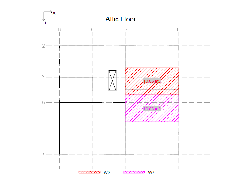
Figure 240 Floor areas acting as seismic loads on first floor piers in the x-direction
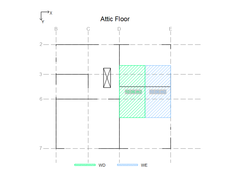
Figure 241 Floor areas acting as seismic loads on first floor piers in the y-direction
Roofs
Input sheet: ‘input_storey
Input name: ‘roof_area_seismic’
Same idea as the floors.
Step 5 - Load distribution: Perpendicular loads
All seismic weight of the building must be carried in both x- and y-directions. The way this is considered is by
assigning ‘perpendicular loads’ to all walls in the in-plane direction. The perpendicular loads consist of the seismic
weights of walls that are connected in the perpendicular directions. This seismic weight also includes the contribution
from non-load-bearing leaves, floors and roofs. In the sections below, the areas of the walls, floors and roofs are
broken down individually and assigned to perpendicular walls.
This is done differently than in the one-storey approach because of how the perpendicular effect
of the wall contributes. This can surely be simplified in the beginning for the floors and roofs,
but for now it has to be done manually
All the areas of walls, floors and roofs that are described below are entered into the sheet ‘Perpendicular loads’. In this sheet, all the contributions to the various walls from all the other walls are added individually, summed up, and lastly entered into ‘input_storey’.
Walls
Load-bearing leaves
Input sheet: ‘input_storey’
Input name: ‘perp_area_wall’
Note: The input is entered into the sheet ‘Perpendicular loads’
Part of the seismic weight of all walls act on perpendicular walls connected to them. The width of the wall that acts on a certain perpendicular wall depends on the distance to the next perpendicular wall. As seen in the example below, the horizontal length of the part to each side is simply half the distance to the next perpendicular wall. When it comes to the height of this part, it is determined based on the height between the floors. When considering the capacity of a specific storey, the height considered is halfway down to the floor below and halfway up to the next floor. The figure below shows an example of the load-bearing leaf areas acting on the perpendicular walls.
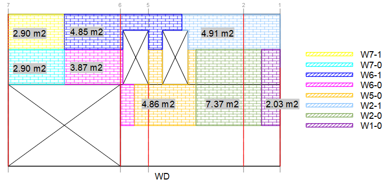
Figure 242 Load-bearing wall areas acting on the perpendicular walls. ..
Add dimensions such as L and L/2 in this figure and various others
Non-load-bearing leaves
Input sheet: ‘input_storey’
Input name: ‘perp_area_outer’, ‘t_outer_perp’
Note: The input is entered into the sheet ‘Perpendicular loads’
The seismic weight of non-load-bearing-leaves act on perpendicular walls in the same way as the load-bearing leaves,
except that in the case of interlocking between the non-load-bearing leaves of the perpendicular walls, it is
assumed that 1.5 meters of the non-load-bearing leaf is carried by the leaf it is interlocked with. The
figure below shows an example of the non-load-bearing leaf areas acting on the perpendicular walls. Furthermore, the
thickness of the non-load-bearing leaves acting as a perpendicular load has to be defined in ‘t_outer_perp’.
Currently only one thickness is supported.
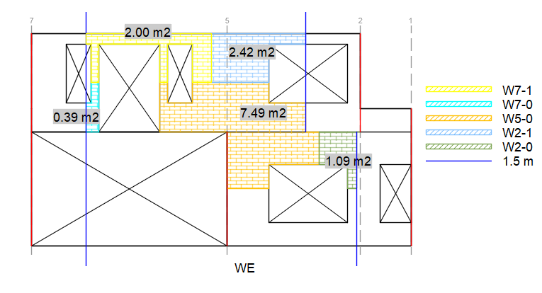
Figure 243 Non-load-bearing wall areas acting on the perpendicular wall storeys.
Floors
Input sheet: ‘input_storey’
Input name: ‘perp_area_floor’
Note: The input is entered into the sheet ‘Perpendicular loads’
The perpendicular effect of floors on walls they do not rest on depends on the geometry of the walls. The seismic weight of the floor is transferred to the wall and from that wall to the perpendicular walls. The figure below shows an example of how the area that acts on the perpendicular walls is determined. The black area in the 2nd figure is the floor area that rests on a timber wall, and therefore this seismic weight is directly assigned to the walls that take up the seismic load in both x- and y-directions. See Floors.
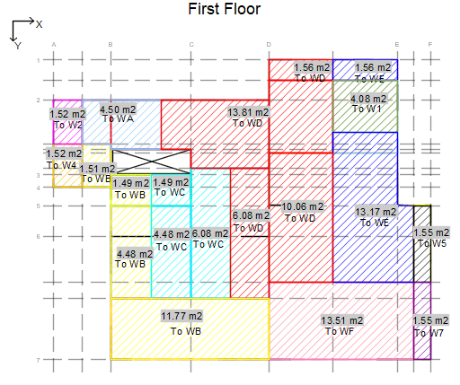
Figure 244 First floor areas acting on the ground storey parts of the perpendicular walls.
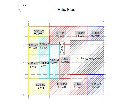
Figure 245 Attic floor areas acting on the first storey parts of the perpendicular walls.
Roofs
Input sheet: ‘input_storey’
Input name: ‘perp_area_roof’
Note: The input is entered into the sheet ‘Perpendicular loads’
For roofs, it is the same idea as the floors. The figure below shows an example of this.
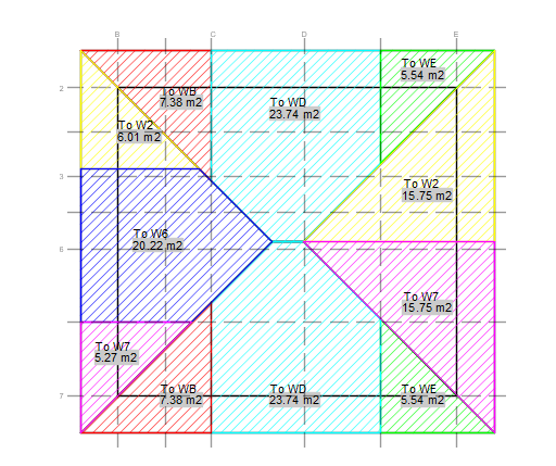
Figure 246 Roof areas acting on the first storey parts of the perpendicular walls.
Step 6 - Input for out-of-plane check
Before performing the out-of-plane check, check that all situations are covered in the back-end as they are currently hard-coded.
Input sheet: ‘input_storey’
Input: ‘perp_walls’
List of walls that are perpendicular to the storey under consideration. Entered as a list, separated by comma and space, e.g. “WB, WD, WE”.Input: ‘area_remove_for_oop’
Area of the nodes and spandrels up until the floor above the piers. This is necessary in order to calculate the load at the top of each storey.Input: ‘ties’
True if cavity wall ties are present.Input: ‘outer’
True if outer leaf is present.Input: ‘oop_type’
Type of the wall: 4, 3, 2, or 1. If NSCE is set as False, oop_type is only relevant if there is a non-load-bearing leaf present as well, and it sets the type of that leaf. If NSCE is set as True, the oop_type is the type of all the leaves of the NSCE wall defined (usually just one leaf).Input: ‘oop_sit’
Override for the out-of-plane situation. This should either be 0 or 6. If set as 0, the situation is determined automatically based on the non-load-bearing leaves and ties. If set as 6, all leaves are checked independently and storey-wise, so a two-storey cavity wall will have four checks in total.Input: ‘oop_height’
The height of the wall considered for the out-of-plane check, as this might be different than that of the in-plane check. For the out-of-plane check it is specifically the height between the top of the lower floor and the bottom of the upper floor.Input: ‘cantilever’
True if cantilever boundary condition at top.Input: ‘bc_top’, ‘bc_bot’
Boundary conditions according to Table H.1 in NPR9998:2018.Input: ‘interstorey_drift’
The interstorey drift assumed for the out-of-plane check.Input: ‘ov_load’
Small overburden load on top of non-load-bearing walls due to e.g. planks running over. 0.3 kN/m for internal walls, 0.15 kN/m for perimeter walls.Input: ‘gable_outer’
True if there is a gable with a non-load-bearing leaf.
Step 7 - Diaphragms
Input sheet: ‘input_diaphragm’
Below is a list of the inputs as general explanation, followed by further elaboration. X in the input names is either N, S, W, E, indicating which edge of the diaphragm that is being considered.
Input: ‘diaphragm’
Name of the diaphragm.Input: ‘storey’
Which storey the diaphragm is on.Input: ‘type’
Type of diaphragm. Floor or roof.Input: ‘supp_wall_X’
Name(s) of supporting element(s), which are walls or beams. If there are multiple elements, write them as a list separated by comma and space.Input: ‘WX_length’
Length(s) of respective supporting element(s). Must be same number of items as ‘supp_wall_X’.Input: ‘adj_diap_X’
True if there is an adjacent diaphragm attached to the same supporting element(s).Input: ‘adj_diap_length_X’
Length(s) along the supporting element(s) where there is an adjacent diaphragm. Must be the same number of items as ‘supp_wall_X’. See the figure below. If ‘adj_diap_X’ is False, leave this empty.Input: ‘L_NS’
Length of diaphragm in NS direction.Input: ‘L_WE’
Length of diaphragm in WE direction.Input: ‘A_pen’
Area of penetrations in diaphragm.Input: ‘height’
Height of roof diaphragm. Leave empty for floors.Input: ‘span_dir’
Span direction. NS or WE.Input: ‘ridge_dir’
Ridge direction for roof diaphragms. NS or WE. Leave empty for floors.Input: ‘supports’
If the diaphragm supports another diaphragm that does not have sufficient supports from beams or walls, indicate the name of that diaphragm here.Input: ‘supported_by’
If the diapraghm does not have sufficient supports from beams or walls, indicate here the name of the diaphragm that supports it.Input: ‘add_walls_XX’
Indicate name of walls (usually NSCE) that do not support the diaphragm, but are still connected and add seismic weight to the diaphragm.Input: ‘add_walls_lengths_XX’
Lengths of respective walls that add seismic weight to the diaphragm.
Diaphragms Elaboration
Adjacent diaphragms
The figure below shows an example of adjacent diaphragms. F5 is adjacent to both F1a and F8. F5 is supported by a beam
for 1.73 m and wall WB for 1.3 m. Along the beam, F5 is adjacent to F1a for 1.73 m, and along WB, it is adjacent to F8
for 0.435 m. Therefore, some of the input for F5 should be:
‘supp_wall_E’: ‘WB, beam’
‘WE_lengths’: `1.3, 1.73’
‘adj_diap_E’:’TRUE’
‘adj_diap_length_E’: ‘0.435, 1.73’
The order of the supporting elements can be switched, but the order has to be consistent.
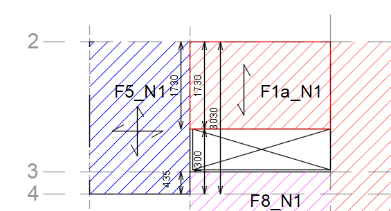
Figure 247 Example of adjacent diaphragm input.
Step 8 - Connections
Input sheet: ‘input_connection’
Below is a list of the inputs as general explanation, followed by further elaboration.
Input: ‘conn_id’
Numeric id used for naming.Input: ‘orientation’
Orientation of connection used for naming. x or y.Will be removed later.Input: ‘supp_element’
Supporting element. Usually wall, but can also be beam. Note that there can only be one supporting element per connection. If you need more elements, then you are most likely defining your connection wrong, or applying a simplification that’s not supported.Input: ‘storey’
Which storey the connection is on.Input: ‘conn_type’
What type of connection it is. See below for all types.Input: ‘diaphragm_type’
What type of diaphragms are connected.Input: ‘diaphragms’
Which diaphragms are connected. For more diaphragms, write them as a list separated by comma and space.Input: ‘direction’
Direction of the connection. NS or WE. NS is same as y, and WE is same as x.Input: ‘conn_mats’
Which materials are interacting at the connection to determine correct friction coefficient.Input: ‘length’
Length of connection.Input: ‘perp_wall’
Connections on Beams not supported yet, so set this to True.
The ‘Data validation’ sheet contains the formatting for the drop down menus for several of the options above. If the menus disappear, see this sheet for the correct formatting of the different inputs.
Input sheet: ‘input_connection_manual’
This sheet is used to enter input and results for connections that are checked manually. This is purely for the purpose of showing these checks in the readout. No calculations are made with this input. Below is a list of the inputs as general explanation, followed by further elaboration.
Input: ‘conn_id’
Numeric id used for naming.Input: ‘orientation’
Orientation of connection used for naming. x or y.Will be removed later.Input: ‘supp_element’
Supporting element. Usually wall, but can also be beam. Note that there can only be one supporting element per connection. If you need more elements, then you are most likely defining your connection wrong, or applying a simplification that’s not supported.Input: ‘storey’
Which storey the connection is on.Input: ‘conn_type’
What type of connection it is. See below for all types.Input: ‘diaphragm_type’
What type of diaphragms are connected.Input: ‘diaphragms’
Which diaphragms are connected. For more diaphragms, write them as a list separated by comma and space.Input: ‘direction’
Direction of the connection. NS or WE. NS is same as y, and WE is same as x.Input: ‘conn_mats’
Which materials are interacting at the connection to determine correct friction coefficient.Input: ‘length’
Length of connection.Input: ‘perp_wall’
Connections on Beams not supported yet, so set this to True.Input: ‘line_point’
Indicate whether the connection is a line or point connection.Input: ‘f_ten’
Perpendicular force acting on connection per meter.Input: ‘f_shear’
Parallel force acting on connection per meter.Input: ‘F_ten’
Perpendicular force acting on connection.Input: ‘F_shear’
Parallel force acting on connection.Input: ‘f_ov’
Overburden load on connection per meter.Input: ‘F_ov’
Overburden load on connection.
Connections elaboration
Connection types:
Enclosed: Connections perpendicular to the spanning direction of the diaphragm where the beams of the floor are laterally enclosed by the masonry.
Parallel: Connections parallel to the spanning direction of the diaphragm where the beams run alongside the wall, and are therefore not connected.
Mechanical: Strong connections between diaphragm and supporting element using e.g. screws, nails, anchors, etc.
Friction: Connections that do not fit the categories above where a diaphragm rests on a supporting element, and the resistance due to friction must be checked against the parallel and perpendicular forces.
Out-of-plane Support: Connections at the top of non-load-bearing walls in order to ensure that the wall is vertically spanning from top to bottom and does not behave as a cantilever.
Performing the analysis
Input
Enter all the input in the excel input file, and adjust the relevant values in slamaParameters.py. Make sure the input file is in the same folder as __mainTSI__.py.
slamaParameters.py
Below are a list of simulator settings parameters that must be set manually.
linspace_res: This sets the number of steps used to calculate the pushover curve. A lower number is computationally cheaper, but can cause errors in the analysis. If the linspace_res is too low, a warning is displayed. For preliminary results, the warning can often be ignored. Also, if running over again to assess results than for those walls giving the warning, the warning can also be ignored.
readout: Set to True if the readout is to be generated.
quick_readout: Set to True if high quality pushover curves are not needed. This is highly recommended until the readout is required for the appendix, since it is computationally expensive to create the high quality curves.
Analysis
Set the ‘filename’ in __mainTSI__.py and run the script to run the analysis..
Results
A readout is generated that contains the all the input and results.