2. Phase 1 - Starting phase
The first three steps of the starting phase are similar to the NLTH and NLPO SDF analysis methods. Please refer to: Phase 1 - Starting phase.
2.1. Step 4: Identification of PSSE’s and NSCE’s (~ ¼ working day)
After investigating the documents from desk study and the documents from the building inspection, the primary seismic elements, secondary seismic elements and non-structural seismic elements should be identified. This can be done using the construction parts in Table 3 in Introduction SLaMA-Approach. Load-bearing walls are in general walls with a foundation underneath. However, the structural engineer is free to choose the seismic load distribution for a building. When identifying primary seismic elements, one or more conditions are valid for these elements:
The wall carries in-plane shear forces from the floor(s) and/or roof(s) above the wall;
Seismic mass is assigned to the wall, i.e. by means of perpendicular loads.
If none of the abovementioned conditions are true and when there is no overburden load present at the top of a wall, then this wall can be identified as a NSCE. Pay attention that the NSCE’s should be stabilized by the PSSE’s.
For further guidance on how to identify and check NSCE’s please refer to: NSCE assessment.
2.2. Step 5: Drawing preparation (~ 1 working day)
Drawings shall be made and organized, such that the structural system is clearly visualized, and the input parameters can be verified. Creating proper and clear drawings has benefits for the engineer, the reviewer and the client. Drawings from desk study or building inspection are not allowed be visible in the self-made drawings in the report and appendix. This prevents drawings to become to overloaded with information and become unclear and unreadable. The drawings from desk study and building inspection may be used to create drawings. Tracing the existing drawings and putting these drawings in a separate layer can be useful. In the end, these layers must be hidden so that they are not visible. The new drawings will be added in the report and to the appendices of the engineering report.
There are no restrictions in the software you use to create the drawings. Autocad is an example of software, with which good and clear drawings can be made. Choose the software, if available, in which you are familiar and have experience, and with which clear and readable drawings can be produced.
The following drawings must be made:
Division of walls at ground floor;
Division of floor diaphragms;
Division of roof diaphragms;
Vertical and seismic load distribution from floors;
Vertical and seismic load distribution from roofs;
2.2.1. Autocad tools
On Box, there is a folder containing Autocad tools and a template. Table 2.1 contains a short description of these tools and the Box location.
Table 2.1: Autocad Tools |
|
|---|---|
Tool |
Description |
VIIA_Layer_Setup.xlsm |
Excel tool for automatic layer creation in Autocad |
legend.lsp |
Function for automatic legend |
FloorArea.lsp |
Function to calculate floor area of hatch.
Result is displayed in text box
|
RoofArea.lsp |
Function to calculate floor area of hatch based
on roof angle. Result is diplayed in text box
|
Box Folders |
|---|
Autocad tools and template
VIIA KENNIS > SLaMa > Autocad Tool >
Autocad Tools
|
Note
When working in Autocad, try to limit opening the application to a minimum since the type of license is as such that RHDHV must pay every time Autocad is launched. If you plan to use Autocad, leave the application open the whole day for example.
2.3. Step 6: Preparing building for calculation phase (~ ½ working day)
2.3.1. Division of walls
In SLaMA, the PSSE’s layout determines how the subsystems should be defined by the engineer. In URM, masonry structural walls constitute the PSSE elements. A subsystem should be organized in a logical way, by following the drawing grid lines. Examples of the wall division can be seen in Figure 2.1.
Because of limitations in the SLaMA tool, walls in the same line need to be separated in the following situations:
Wall thickness - if a wall consists of different thicknesses;
Material - if in one line there are walls or piers present with different materials;
Presence of interlocking - if there is no interlocking between two walls or piers in one line.
Note
If in one line multiple separately considered walls are present, they all should behave in the same way, either linearly (complies on strength) or non-linearly (complies only on deformation). If close to (or in line with) a linear behaving (commonly associated with ‘shear’ as governing failure type) there are non-linear behaving (commonly associated with ‘rocking’ as governing failure type) walls present, these non-linear walls will not be able to reach the desired deformation to comply. In this case, in practice this means that the linear wall will have to carry the seismic mass of the non-linear walls. This should be processed in the SLaMA-Tool.
Note
Attention should be paid to situations where certain walls can be neglected in the analysis. If the offset of the jump between two parallel walls is relatively short, for example shorter than 0,7 m, then this short wall can be omitted. The mass of this short wall can be added to the adjacent walls as an additional mass.
Cavity walls are usually considered separately. If there are no cavity ties present in the wall, it is assumed that the leaves do not work together. Therefore, they should be split so that the leaves can be assessed separately from each other.
The drawing(s) indicating the wall numbers should contain the following information :
PSSE’s: W01, W02, …, WA, WB, …, following grid lines. Numbers horizontal, letters vertical;
NSCE’s;
Dimension lines of walls and openings;
Grid lines and Global Coordinate System (GCS)
Beams, columns;
Legend indicating walls, beams, columns including material.
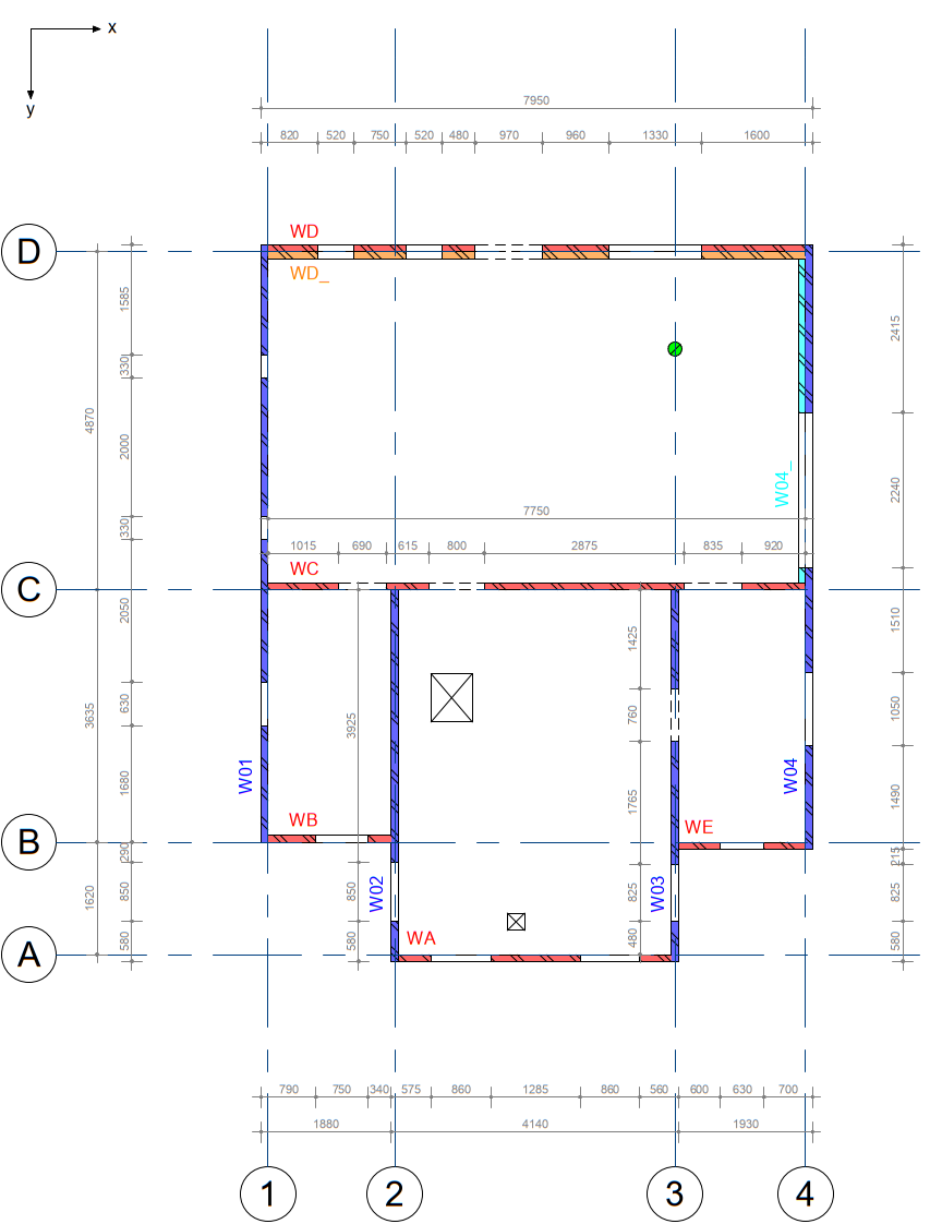
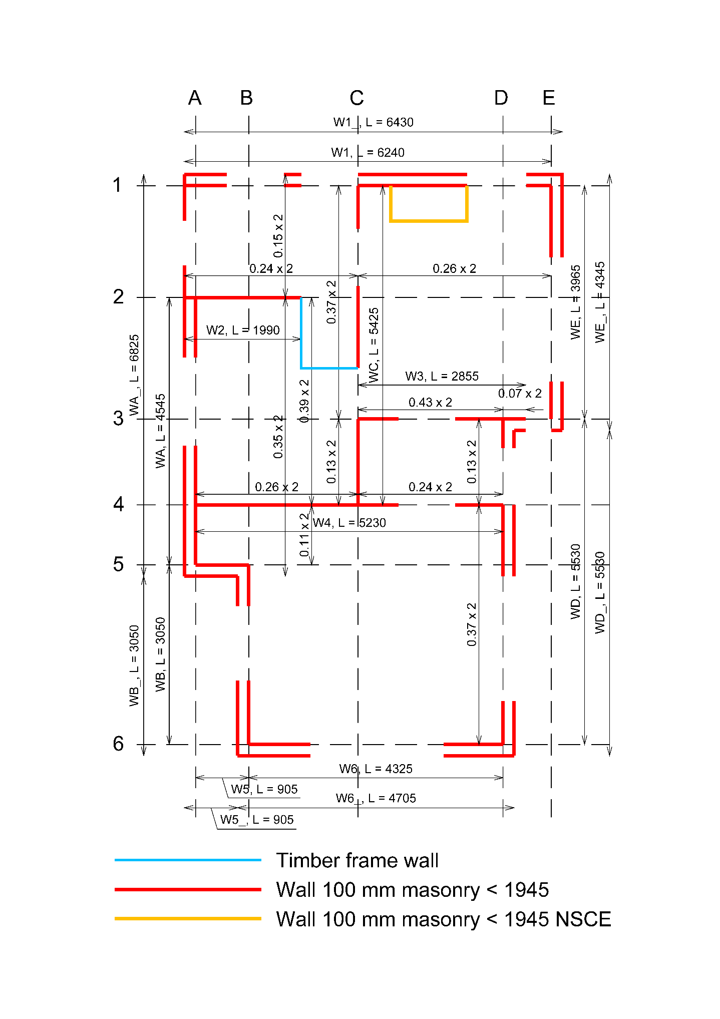
Figure 2.58 Examples of ways to show division of walls
2.3.2. Load distribution in general
The SLaMA-tool as described in section SLaMA-tool performs in-plane and out-of-plane checks for masonry walls based on the entry of forces acting on each wall. SLaMA-tool categorizes the forces based on the origin.
The first category of forces acting on a wall is relevant to the load that is applied from a gable on top or from the part of the wall, between the floor level and the gutter, when the wall extends above the floor level. The user, can also, specify arbitrary vertical loads that the wall bears. Namely, the force parameters can be identified as:
A_gable: Surface area of the masonry (i.e. without openings) [m2];
A_gutter: Surface area of the gutter (i.e. without openings) [m2];
F_other: Arbitrary normal force acting on the wall [N].
The second category of forces acting on a wall includes the forces from the floor- and/or roof diaphragm(s), that is/are resting on the wall. The following force parameters need to be defined per floor or roof diaphragm:
Resting load: Type of floor or roof that rests on the wall [N/m2];
A_axial: Area contributing to the axial superimposed load of the wall [m2];
A_lateral: Area contributing to the additional lateral load that should be resisted by the wall [m2];
Axial loads are vertical loads from floors and/or roofs. In case of roof loads, the inclined area of the roof should be taken (!). Lateral loads are loads which are “leaning” on a primary seismic element during an earthquake. For example, the axial load contribution of the floor bearing area acting on a column contributes as seismic mass to be carried by the lateral resistant elements (PSSE masonry walls). This is illustrated in Figure 2.2.
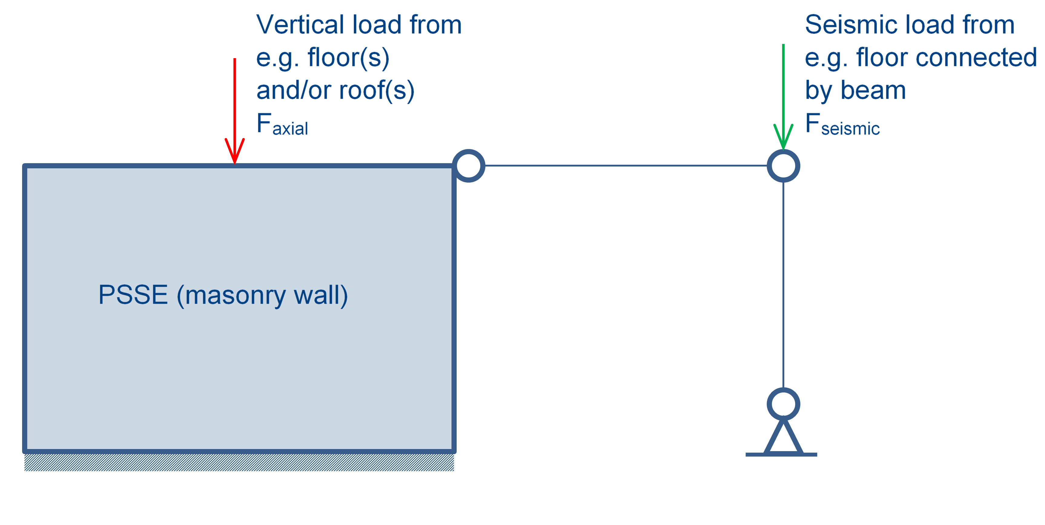
Figure 2.59 Axial load (red) and lateral load (green) on PSSE element
For information concerning loads and load combinations, see the Basis of Design (Uitgangspuntenrapport) on Box.
Box Folders |
|---|
Uitgangspuntenrapport (in Dutch)
VIIA KENNIS > SLaMa >
VIIA_QE_R2069 Uitgangspuntenrapport Engineering SLaMa.pdf
|
Note
The value of the self-weight, or dead load (g_k), of the floor depends on the type of the floor. For timber_floor_type_1 it is equal to 0,2 kN/m2 (200 N/m2). This only includes the timber beams and sheeting. If a ceiling (0,15 kN/m2) is present, then this weight needs to be added to the floor self-weight as well. In this case timber_floor_type_2 is the representative floor type. For concrete_floor_type_1 the dead load is equal to 2.5 kN/m2 (2500 N/m2). The variable (i.e. imposed) floor load (q_k) is in general equal to 1,75 kN/m2 (1750 N/m2). If for example lightweight non-load bearing partition walls are present on top of the floor (0,5 kN/m2), then this load needs to be added to the variable (i.e. imposed) load.
The geometry of the roof defines its characteristic self-weight, or dead load (g_k). A distinction is made between sloping and flat roof. The dead load of a sloping roof is assumed to be equal to 0,65 kN/m2 (650 N/m2). This includes the roof tiling. The dead load of a flat roof depends on the finishing layer on top. For bituminus finishing layer a self-weight of 0,1 kN/m2 (100 N/m2) is considered for the falt roof, whereas the self-weight of a roof with a layer of gravel on top of the bituminous layer is equal to 0,6 kN/m2 (600 N/m2). The variable (i.e. imposed) roof load (q_k) is usually equal to 1,00 kN/m2 (1000 N/m2), irrespective or the roof geometry.
Also refer to the Basis of Design, where the loads are found. If desired, above load values can also be changed.
In the report, there should be a clear description of the load transfer to cavity walls. This is an important aspect and assumption in the analysis. Usually, the pictures made during the building inspection are satisfactory in judging the vertical load distribution from floors and roofs to the inner leaves and/or outer leaves of a cavity wall. An example of a floor resting on the outer leaf is the presence of anchors visible from the outside of the building.
2.3.3. Vertical (axial) load distribution on walls from floors
Floors can be spanning in one or two directions, depending on construction type and materials. In general, timber floors are spanning in one direction. Concrete floors may span in one- or two directions. In Figure 2.3 an example of a timber floor spanning in one direction is given. The spanning direction is parallel to the beams.
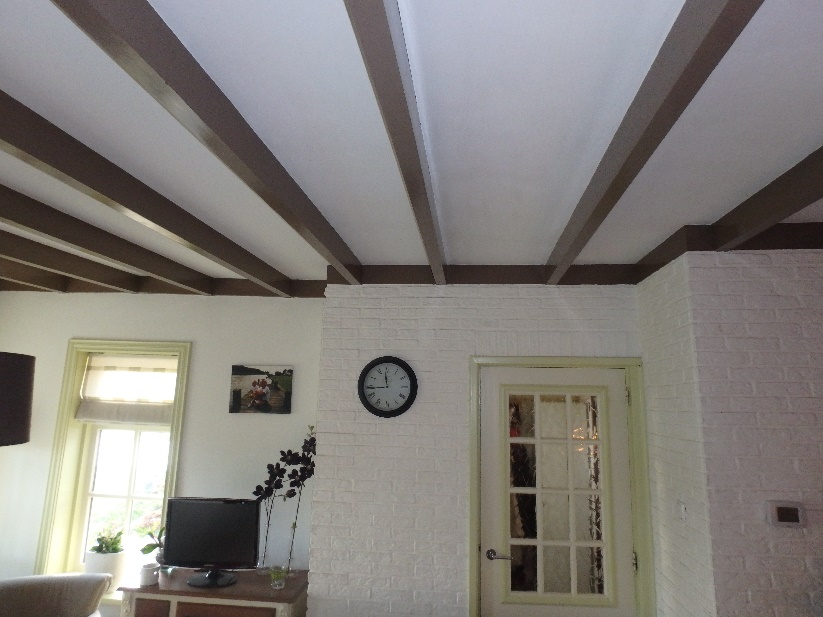
Figure 2.60 Example of floor spanning in one direction (along beams)
The basics of the determination of tributary areas are explained considering the examples given in Figure 2.4.
Note
Axial load, carried by load bearing non-seismic elements (i.e. axial load contribution of the floor area acting on the column) contributes only as seismic mass to be carried by the PSSE’s as seismic load, as described in the following section about Perpendicular/tributary load distribution.
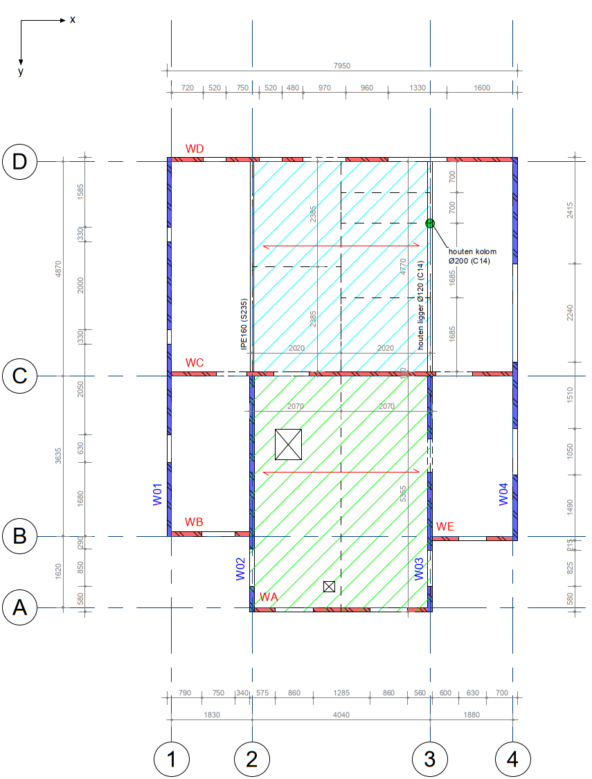
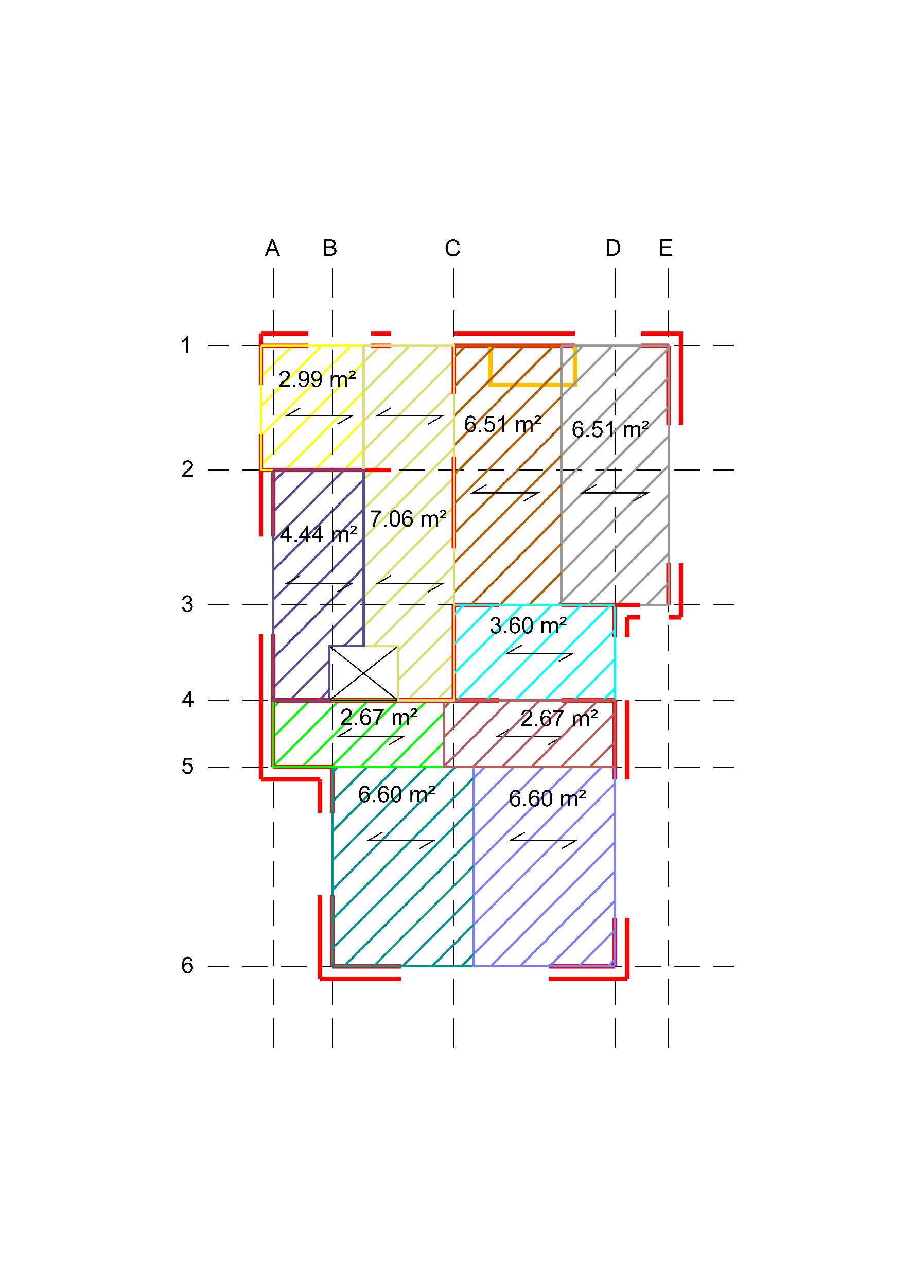
Figure 2.61 Examples of load distribution on walls - loads from floor
2.3.4. Vertical (axial) load distribution on walls from (inclined) roof
Roofs can also span in one direction or two directions, as can be seen in the following figures. In Figure 2.5 an example of a timber roof is given, which is spanning from left to right (‘rafter roof’ type). Figure 2.6 shows a roof which spans from gable to gable (‘purlin roof’ type).
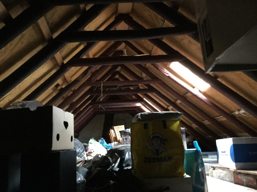
Figure 2.62 Example of roof spanning from left to right (rafter roof).
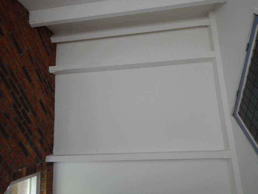
Figure 2.63 Example of roof spanning from gable to gable (purlin roof).
The basics of the determination of tributary areas are explained considering the examples given Figure 2.7. The following information was taken into account to define the tributary areas for the example on the left of the figure:
Roof span is parallel to the x-direction;
Load bearing non-seismic elements such as timber columns are not able to withstand seismic loads in general;
In the x-direction, red walls are vertical lateral force-resisting elements, and in the y-direction, the blue ones are vertical lateral force-resisting elements;
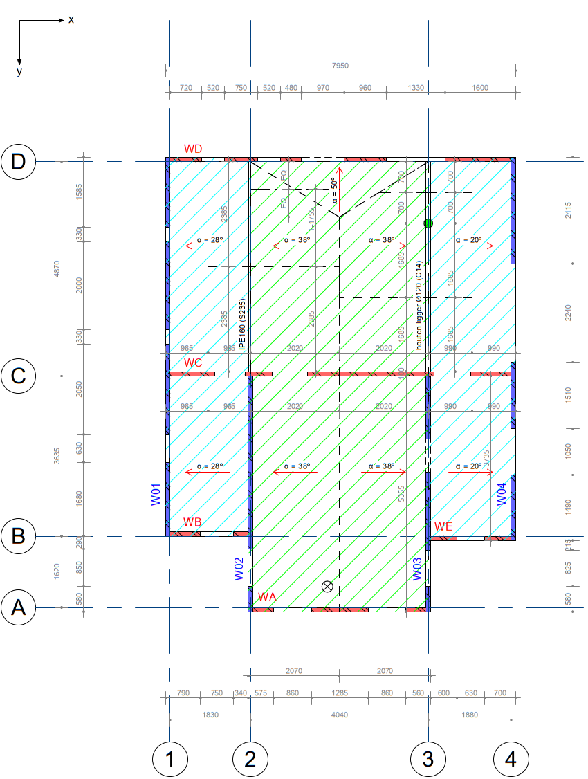
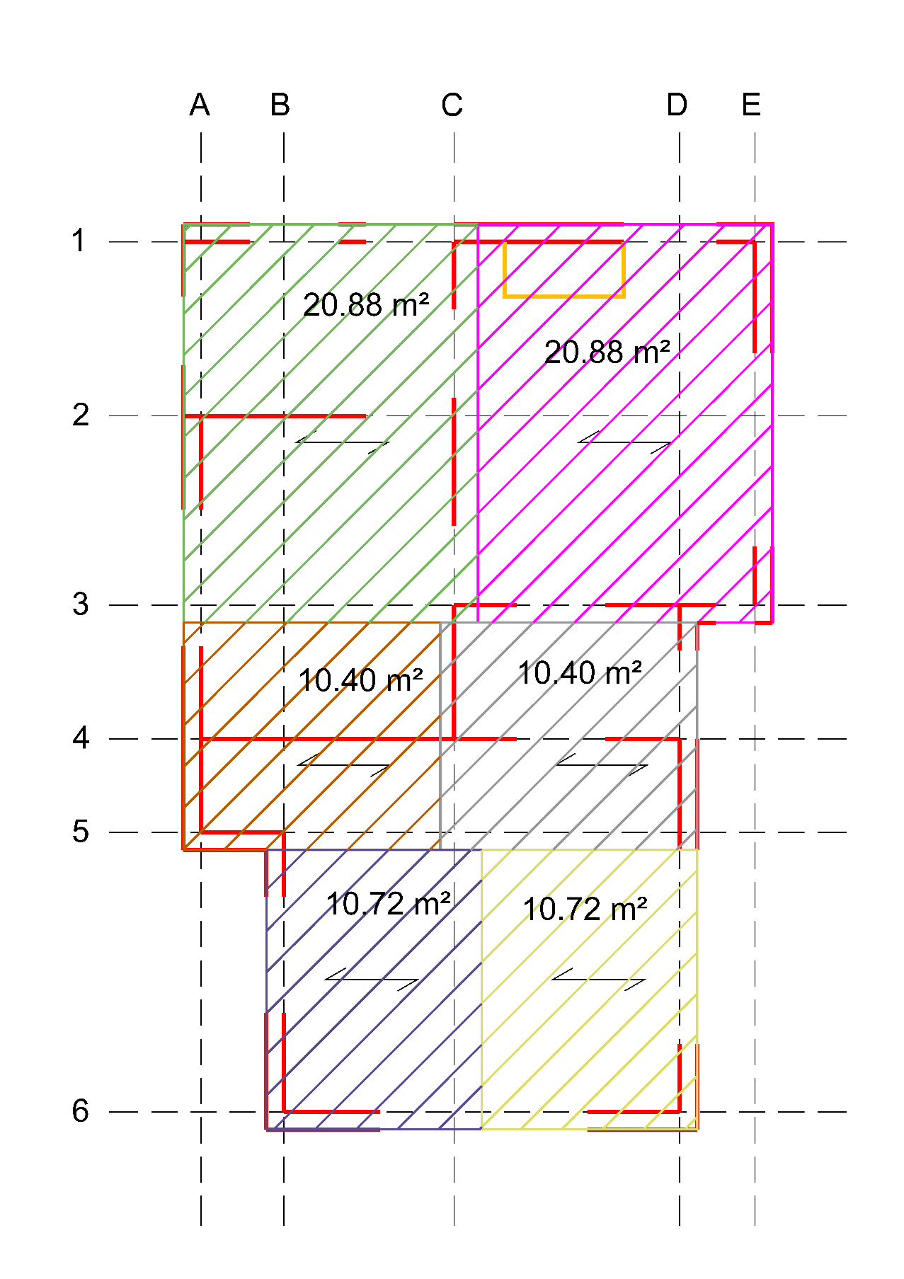
Figure 2.64 Examples of load distribution on walls from (inclined) roof.
Note
Axial load carried by load bearing non-seismic elements (i.e. axial load contribution of the roof area acting on the column) only contributes as seismic mass to be carried by the lateral resistant elements as seismic load.
Note
The tributary areas shown in Figure 2.7 are the horizontal projections of the “real” tributary areas of the roof since the roofs are usually inclined. For the calculations the area of the “real” inclined areas should be used unless the inclination is considered negligible.
There are cases that an intermediate attic floor (‘vliering’, see Figure 2.8) is present between first floor and roof, usually close to the top. If an attic floor is present in a roof, the permanent and variable loads on this floor must be added to the roof as additional permanent load. This can be done with the help of the following formula. The permanent load of the roof including a floor now becomes:

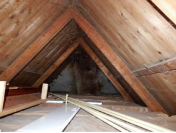
Figure 2.65 Example of a ‘vliering’
2.3.5. Load contribution from gables and walls above attic floor
An example of the gable load distribution to wall is given in Figure 2.9 (gable area in blue). In this figure the gable rests on a wall defined as WA. Calculate the area of the gable and insert in A_gable. Exclude the openings in the gable walls. If there is a part of a wall that reaches above the attic floor, then this part is added to A_gutter.
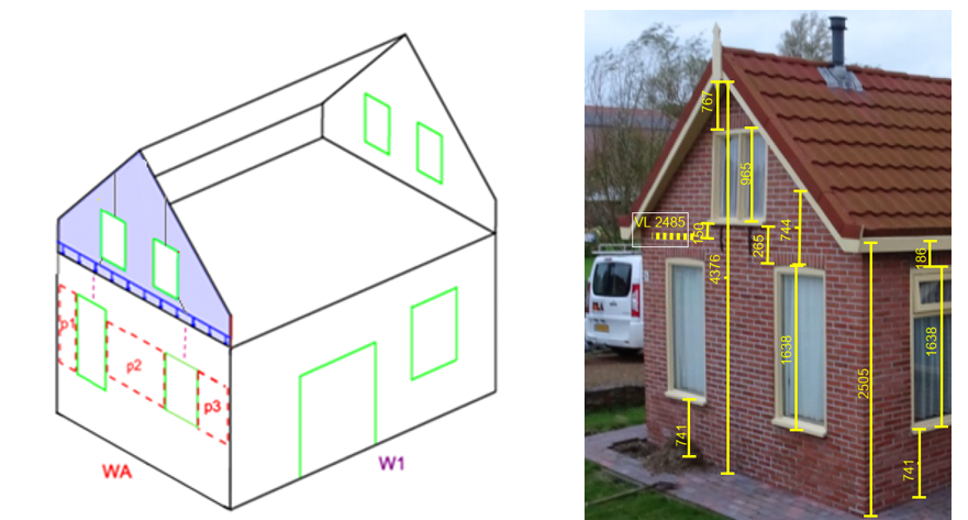
Figure 2.66 Surface area from gables and walls above attic floor
2.3.6. Other loads
The seismic load of elements like chimneys and (internal) masonry chimney ducts can be grouped in “other” loads. These loads do not act as an overburden load on a wall like a floor or roof but only as additional seismic mass (redundant load).
Note
Not the whole internal chimney is considered, since a part will directly be transferred to the ground floor and thus the foundation.
2.3.7. Perpendicular/tributary load distribution
Seismic mass acting perpendicular to a considered wall (also called perpendicular load), contributes to seismic loads that are carried by the vertical lateral force-resisting elements in that direction. This perpendicular load becomes part of the tributary load
The basics of the determination of perpendicular wall intervals are explained considering the example given in Figure 2.10.
The position of the perpendicular wall into consideration is defined by value from within the interval <0,1> (according to the SLaMA-tool). Note that for each direction, all walls should be present in the analysis (!). When analyzing for example the x-direction in the figure above, all blue walls should be present as perpendicular walls. When analyzing the y-direction, all red walls should be present as perpendicular walls. This is important in order not to underestimate the seismic mass.
Note
In the case of NSCE’s, the PSSE’s have to carry the seismic mass of the NSCE’s to stabilize them. Vice versa, the NSCE’s do not carry the seismic mass of the PSSE’s (otherwise they are PSSE’s as well).
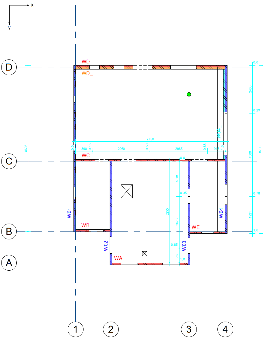
Figure 2.67 Example of perpendicular load distribution (intervals).
2.3.8. Division of floor- and roof diaphragms
When dividing floor diaphragms, the edges of each diaphragm should be a PSSE, see the examples in Figure 2.11. Within the floor diaphragm, there should be no PSSE’s present. The PSSE’s at the edges of the floors are now able to transfer the (in-plane) forces resulting from the floor diaphragms. The floor diaphragm may contain NSCE’s below the diaphragm. Pay attention that, in this case, an additional load on the floor diaphragm must be specified. This additional load should contain the seismic mass of the NSCE’s below the diaphragm. The seismic mass is equal to the total length of the NSCE’s below the diaphragm multiplied by NSCE thickness, half of the NSCE height and the material density. Pay attention if the floor diaphragm is resting on the inner leaf or outer leaf in case of a cavity wall.
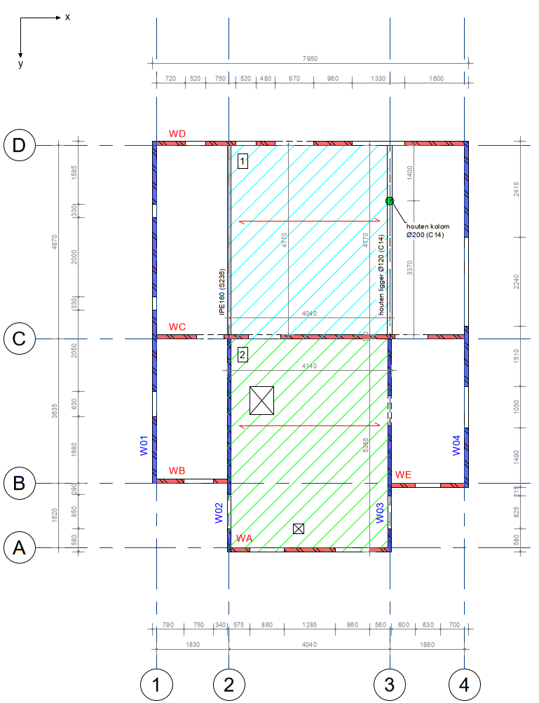
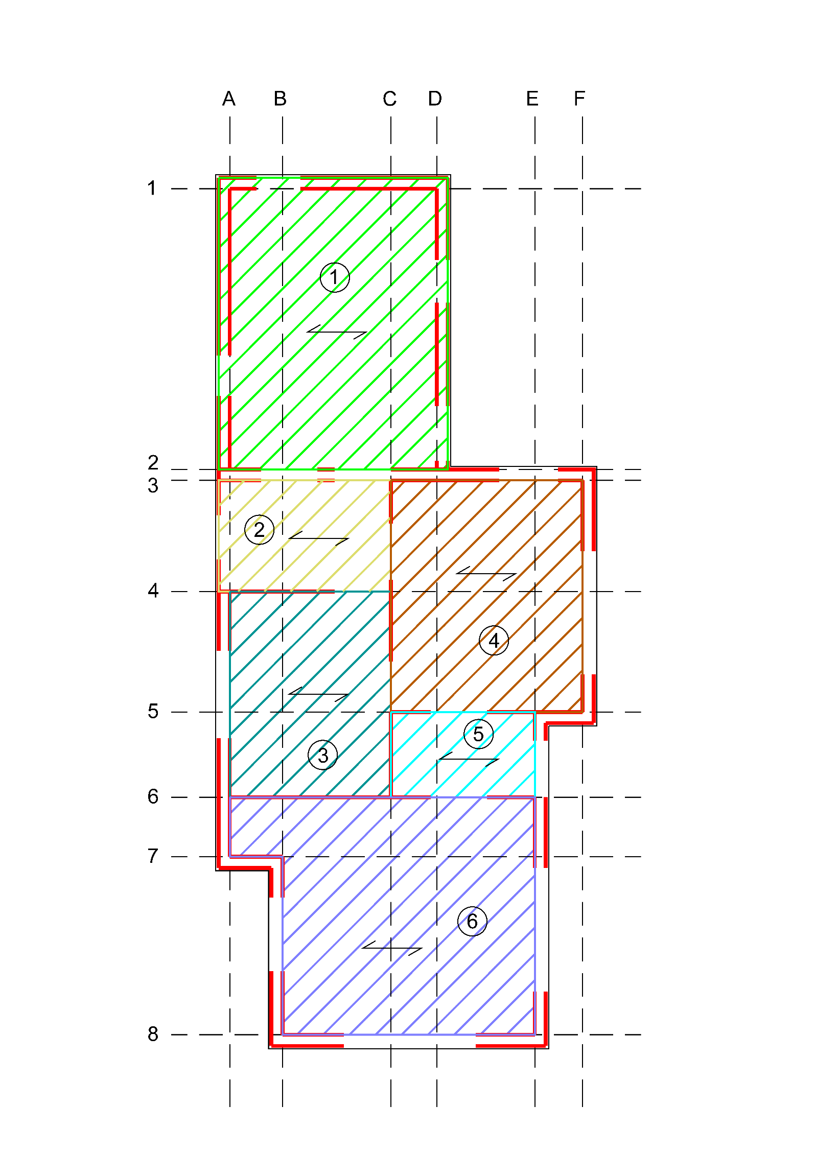
Figure 2.68 Examples of division of floor diaphragms.
The roof diaphragms can be divided into rectangles based on discontinuities in the building plan, see the examples in Figure 2.12. Pay attention if the roof diaphragm is resting on the inner leaf or outer leaf in case of a cavity wall.
The drawing(s) indicating the division of floor- and roof diaphragms should contain the following information:
PSSE’s, naming is not necessary;
NSCE’s optional;
Indication of diaphragms with spanning direction and number;
Grid lines and Global Coordinate System (GCS)
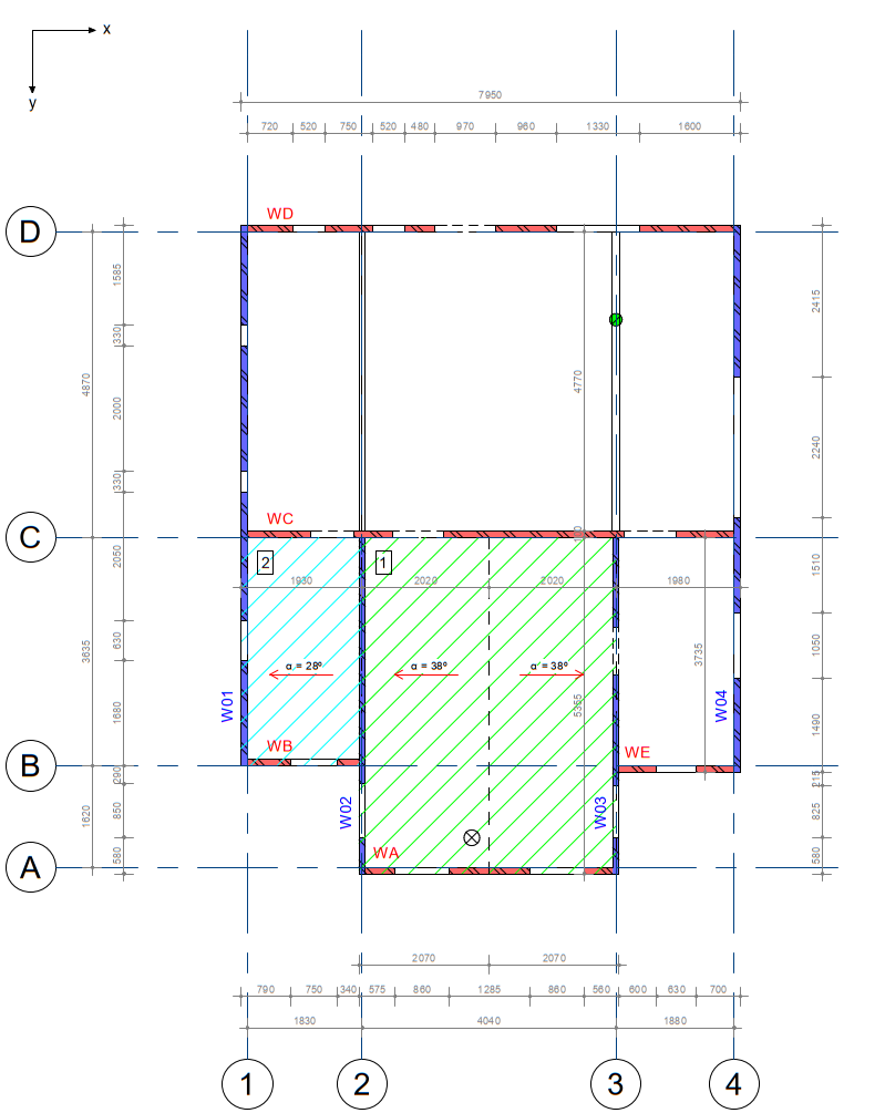
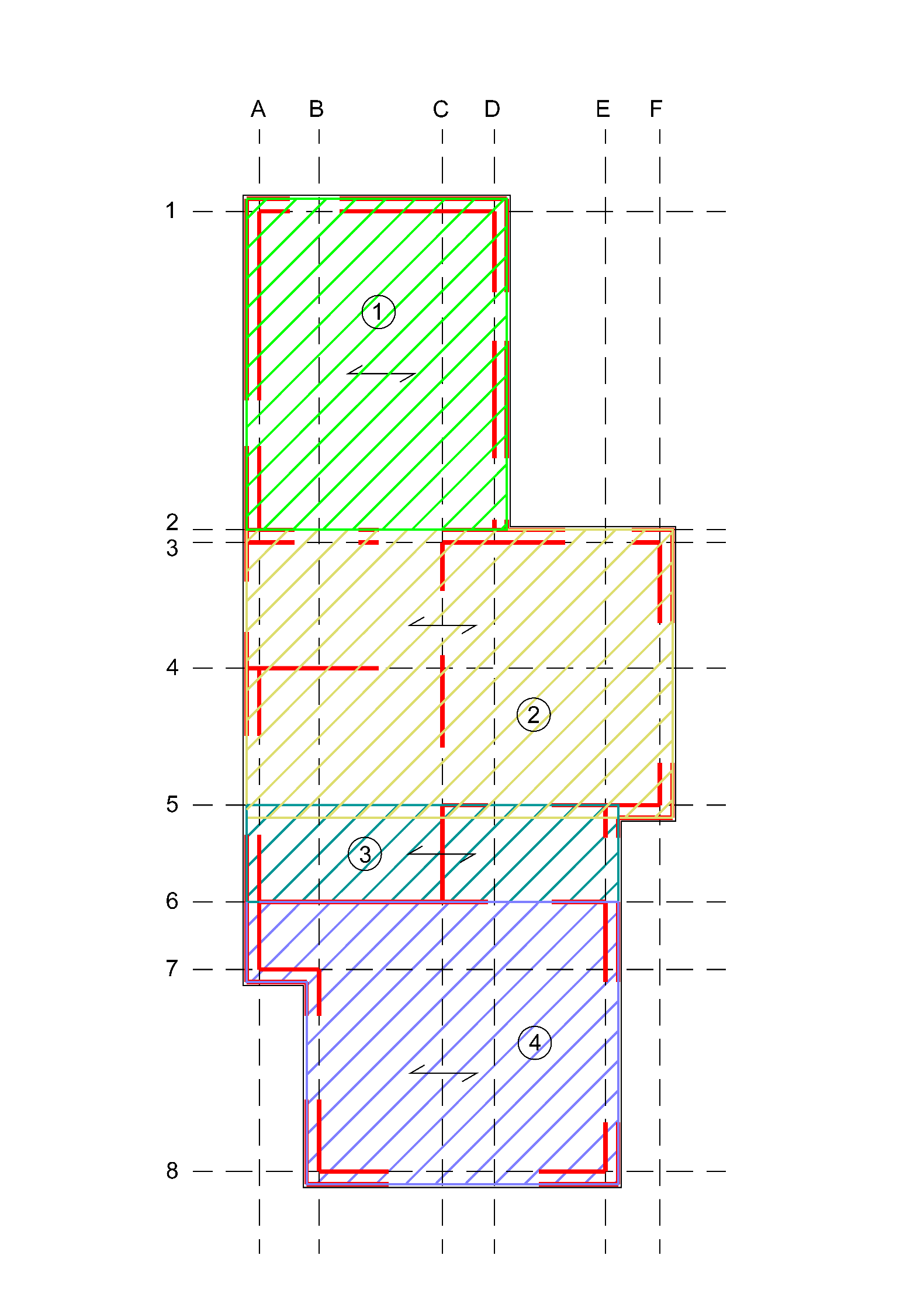
Figure 2.69 Examples of division of roof diaphragms.
2.4. Step R1: ER appendix B - Structural setup of the building
The schematisation of the object is included in Appendix C1 and C4 of the engineering report. Please refer to: Step R2: Reporting NSCE assessment.
Note
The components of Appendix C1 are slightly different for objects, that are analyzed with the SLaMA method, since the analysis input is also different compared to the NLTH/NLPO SDF analysis methods.