Further reading on close interfaces in DIANA
The close line interface is applied between two shape edges which are coincident. If there are more coincident edges they will be disconnected after the interface is applied in DIANA. In addition, the edge nodes will be disconnected. The structural engineer should be careful and reconstruct all the connections between the edges and the nodes.
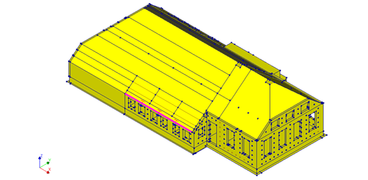
In this picture, a close interface is applied between the roof (source) and the outer wall leaf (target):
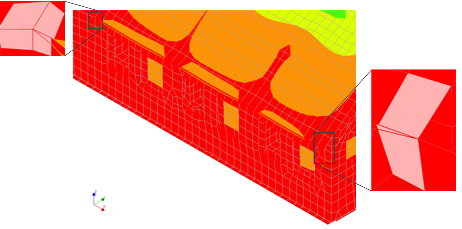
After the mesh is generated, the edge nodes are checked to see how many nodes exist:
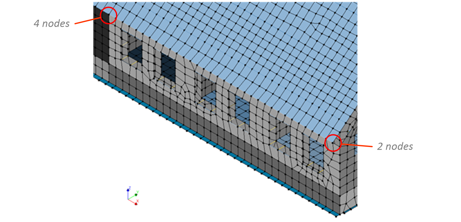
Due to the closed line interface, both of the sides are completely disconnected at the nodes. When a linear static analysis is performed based on the current situation of the model. It can be noticed that the nodes of the elements are totally disconnected.
To fix this problem, the nodes should be connected to each other. The ‘Unite’ connection can be used:
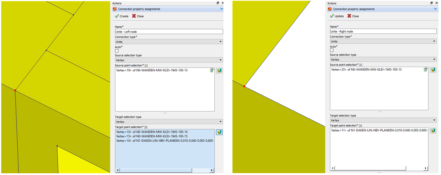
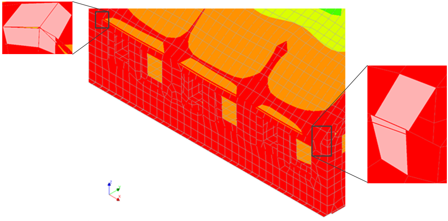
After meshing again, the nodes are checked. Only one node is found for each end meaning that the attached elements are connected again.

A new linear static analysis is performed to check the new behaviour of the ends of the connection: